EP0317398A1 - Gasgelagerte Turbomaschine - Google Patents
Gasgelagerte Turbomaschine Download PDFInfo
- Publication number
- EP0317398A1 EP0317398A1 EP88402826A EP88402826A EP0317398A1 EP 0317398 A1 EP0317398 A1 EP 0317398A1 EP 88402826 A EP88402826 A EP 88402826A EP 88402826 A EP88402826 A EP 88402826A EP 0317398 A1 EP0317398 A1 EP 0317398A1
- Authority
- EP
- European Patent Office
- Prior art keywords
- wheel
- turbomachine
- axial
- shaft
- stop
- Prior art date
- Legal status (The legal status is an assumption and is not a legal conclusion. Google has not performed a legal analysis and makes no representation as to the accuracy of the status listed.)
- Granted
Links
- 238000004378 air conditioning Methods 0.000 abstract description 2
- 239000012530 fluid Substances 0.000 description 7
- 230000006835 compression Effects 0.000 description 1
- 238000007906 compression Methods 0.000 description 1
- 238000001816 cooling Methods 0.000 description 1
- 230000007257 malfunction Effects 0.000 description 1
- 230000004048 modification Effects 0.000 description 1
- 238000012986 modification Methods 0.000 description 1
Images

Classifications
-
- F—MECHANICAL ENGINEERING; LIGHTING; HEATING; WEAPONS; BLASTING
- F01—MACHINES OR ENGINES IN GENERAL; ENGINE PLANTS IN GENERAL; STEAM ENGINES
- F01D—NON-POSITIVE DISPLACEMENT MACHINES OR ENGINES, e.g. STEAM TURBINES
- F01D25/00—Component parts, details, or accessories, not provided for in, or of interest apart from, other groups
- F01D25/18—Lubricating arrangements
- F01D25/22—Lubricating arrangements using working-fluid or other gaseous fluid as lubricant
-
- F—MECHANICAL ENGINEERING; LIGHTING; HEATING; WEAPONS; BLASTING
- F01—MACHINES OR ENGINES IN GENERAL; ENGINE PLANTS IN GENERAL; STEAM ENGINES
- F01D—NON-POSITIVE DISPLACEMENT MACHINES OR ENGINES, e.g. STEAM TURBINES
- F01D25/00—Component parts, details, or accessories, not provided for in, or of interest apart from, other groups
- F01D25/16—Arrangement of bearings; Supporting or mounting bearings in casings
- F01D25/166—Sliding contact bearing
- F01D25/168—Sliding contact bearing for axial load mainly
Definitions
- the present invention relates to an improvement to turbomachines mounted on a gas bearing.
- FIG. 1 shows a turbomachine comprising three rotors or wheels capable of being used in air conditioning systems for aircraft.
- This turbomachine essentially comprises a fan wheel 1 constituted by an axial wheel comprising a hub 1A extending by blades 1B forming between them channels through which the fluid, namely air, can flow.
- the fluid flow path is represented by the arrows f in FIG. 1.
- the axial wheel 1 is mounted at the end of a hollow shaft 2. More specifically, the axial wheel 1 is mounted on a tie rod 3 and is secured to the shaft 2 by means of a nut system 4.
- the fan part of the turbomachine further comprises an air distributor 5 bringing the outside air to the blades 1B of the axial wheel 1.
- the shaft 2 is mounted inside a stator 6 with the interposition of lift means constituted by gas bearings 7,8.
- a compressor wheel 9 constituted by a centrifugal radial wheel is fixed on the shaft 2.
- the shaft 2 consists of a first part 2A into which a second part 2B is inserted.
- the wheel 9 is held in abutment between a shoulder provided on the shaft 2B and the end of the part 2A.
- a distributor 10 brings the air to the wheel 9 which, after compression, is diffused in the volutes 10 from where it escapes as represented by the arrows f1.
- the 1 comprises a turbine wheel 11 constituted by a centrifugal radial wheel, this wheel 11 is fixed to the end of the part 2B of the shaft 2 opposite to the part supporting the wheel 9.
- the two parts 2A and 2B of the shaft are held in position by means of the tie rod 3.
- the turbine wheel 11 is supplied with air by a distributor 12 and the relaxed air is evacuated by the diffuser 13.
- the path of the fluid is in this case represented by the arrows f2.
- the gas bearings 7 and 8 are positioned respectively between the fan wheel 1 and the compressor wheel 9 and between the compressor wheel 9 and the turbine wheel 11 so as to compensate for the radial thrust s '' exercising on the shaft during the rotation of the wheels.
- an axial stop 15 is provided. This stop is constituted by a disc held between two walls 16,17. To cool this stop, it is preferably positioned near the turbine wheel 11, and a fluid supply is made from scrolls 14 taking up the relaxed air.
- the turbomachine comprises pipes 16 and 17 allowing the circulation of gas between the casing of the stator and the hollow shaft 2 as well as inside the tree as represented by the arrows f3.
- turbomachinery of the above type it is important to obtain correct operation of the gas bearings 7,8 positioned respectively between the fan wheel 1 and the compressor wheel 9 and between the compressor wheel 9 and the turbine wheel 11, that the mobile is as light and as short as possible in order to obtain the highest possible natural frequency.
- the stop is an independent part fixed to the shaft 2 which does not make it possible to obtain the shortest possible assembly.
- the stopper is preferably positioned near the turbine wheel, which more loads the bearing positioned between the compressor wheel and the turbine wheel. This can lead to a malfunction of the assembly.
- the present invention therefore aims to a new positioning of the stop which overcomes these drawbacks.
- the subject of the present invention is a turbomachine mounted on at least one gas bearing, said turbomachine comprising at least one axial wheel and an axial stop, characterized in that the axial stop is integrated into the axial wheel.
- the stop is constituted by at least two articulated pads positioned on each side of the hub of the wheel.
- the stop is integrated into the median rotor.
- the position of the different wheels on the shaft can be swapped.
- the fan wheel can be the middle wheel while the compressor wheel can be positioned at one end of the shaft.
- the turbine wheel can be positioned in the center or at the other end.
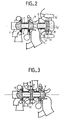
- the fan wheel 1 is constituted by an axial wheel fixed on the end of the shaft 2 as in the embodiment of FIG. 1.
- the compressor wheel 9 is fixed to the middle of the shaft 2 and the turbine wheel 11 is fixed to the other end of the shaft 2.
- the shaft 2 is supported by two gas bearings 8,7 positioned respectively between the wheels 11 and 9 and between the wheels 9 and 1.
- the hub 1A ′ of the axial wheel 1 has a larger diameter than the hub 1A of the embodiment of FIG. 1. In fact, this hub 1A ′ is used to serve as an axial stop in accordance with the present invention.
- the hub 1A ′ is positioned between at least two pads 21, 22. These pads 21, 22 are fixed in an articulated manner to the wall of the stator 6. Preferably, the pads are fixed to the wall of the stator 6 by means of the spring. The pads 21 and 22 are thus placed inside the stator so as to receive the flow of fluid circulating in the rotor to produce a gas stop.
- the hub 1A ′ of the axial wheel 1 is extended by blades 1B ′ allowing the fluid to flow.
- the use of an integrated stop on the axial wheel of the fan makes it possible to reduce the total length of the turbomachine as well as the weight of this machine. This makes it possible to have a higher natural frequency and also a greater speed of rotation.
- the axial wheel forming a stop is not placed at one end of the shaft 2 as in FIG. 2 but is placed at the middle of the shaft between the two radial wheels 11 and 9.
- the compressor wheel 9 is positioned at one end of the shaft 2.
- the axial stop is constituted by a set of pads 21 and 22 positioned inside the stator 2 on each side of the hub 1A ′ of an axial wheel 1 whose diameter of the hub has been enlarged compared to the usual axial wheels.
- the hub 1A ′ is extended by blades 1B ′ allowing the fluid to flow.
- gas lift bearings 8,7 On each side of the axial wheel 1A, fixed to the shaft 2, there are provided gas lift bearings 8,7, as in the embodiments of FIGS. 1 and 2.
Landscapes
- Engineering & Computer Science (AREA)
- Mechanical Engineering (AREA)
- General Engineering & Computer Science (AREA)
- Structures Of Non-Positive Displacement Pumps (AREA)
Applications Claiming Priority (2)
| Application Number | Priority Date | Filing Date | Title |
|---|---|---|---|
| FR8715845 | 1987-11-17 | ||
| FR8715845A FR2623247B1 (fr) | 1987-11-17 | 1987-11-17 | Perfectionnement aux turbomachines montees sur palier a gaz |
Publications (2)
| Publication Number | Publication Date |
|---|---|
| EP0317398A1 true EP0317398A1 (de) | 1989-05-24 |
| EP0317398B1 EP0317398B1 (de) | 1993-04-07 |
Family
ID=9356859
Family Applications (1)
| Application Number | Title | Priority Date | Filing Date |
|---|---|---|---|
| EP19880402826 Expired - Lifetime EP0317398B1 (de) | 1987-11-17 | 1988-11-10 | Gasgelagerte Turbomaschine |
Country Status (3)
| Country | Link |
|---|---|
| EP (1) | EP0317398B1 (de) |
| DE (1) | DE3880094T2 (de) |
| FR (1) | FR2623247B1 (de) |
Cited By (2)
| Publication number | Priority date | Publication date | Assignee | Title |
|---|---|---|---|---|
| EP0547279A1 (de) * | 1990-08-03 | 1993-06-23 | United Technologies Corporation | Kühlung für Lager einer Luftkreisanlage |
| EP1445428A1 (de) * | 2003-01-21 | 2004-08-11 | Hamilton Sundstrand Corporation | Turbokompressor mit Luftlagerung und selbstschliessendem Luftversorgungsventil |
Families Citing this family (2)
| Publication number | Priority date | Publication date | Assignee | Title |
|---|---|---|---|---|
| UA31519A (uk) * | 1998-09-21 | 2000-12-15 | Валерій Вікторович Манческо | Високотемпературна газова турбина, переважно газотурбинного двигуна |
| CN113374729B (zh) * | 2021-06-24 | 2026-04-24 | 珠海格力电器股份有限公司 | 一种循环机 |
Citations (4)
| Publication number | Priority date | Publication date | Assignee | Title |
|---|---|---|---|---|
| DE562716C (de) * | 1932-10-28 | Franz Burghauser Dipl Ing | Dampf- oder Gasturbine oder Verdichter mit dampf- oder gasgeschmierten und gleichzeitig dichtenden Lagern | |
| GB817897A (en) * | 1955-12-28 | 1959-08-06 | White & Co Ltd Samuel | Improvements relating to elastic fluid turbo machines such as steam turbines and aircompressors |
| DE2233970B1 (de) * | 1972-07-11 | 1973-11-22 | Maschinenfabnk Augsburg Nürnberg AG, 8900 Augsburg | Zweistufig aufgeladene hubkolbenbrennkraftmaschine |
| US4503683A (en) * | 1983-12-16 | 1985-03-12 | The Garrett Corporation | Compact cooling turbine-heat exchanger assembly |
Family Cites Families (1)
| Publication number | Priority date | Publication date | Assignee | Title |
|---|---|---|---|---|
| GB1105658A (en) * | 1964-07-22 | 1968-03-13 | Ass Elect Ind | Improvements in or relating to turbines |
-
1987
- 1987-11-17 FR FR8715845A patent/FR2623247B1/fr not_active Expired - Lifetime
-
1988
- 1988-11-10 DE DE19883880094 patent/DE3880094T2/de not_active Expired - Fee Related
- 1988-11-10 EP EP19880402826 patent/EP0317398B1/de not_active Expired - Lifetime
Patent Citations (4)
| Publication number | Priority date | Publication date | Assignee | Title |
|---|---|---|---|---|
| DE562716C (de) * | 1932-10-28 | Franz Burghauser Dipl Ing | Dampf- oder Gasturbine oder Verdichter mit dampf- oder gasgeschmierten und gleichzeitig dichtenden Lagern | |
| GB817897A (en) * | 1955-12-28 | 1959-08-06 | White & Co Ltd Samuel | Improvements relating to elastic fluid turbo machines such as steam turbines and aircompressors |
| DE2233970B1 (de) * | 1972-07-11 | 1973-11-22 | Maschinenfabnk Augsburg Nürnberg AG, 8900 Augsburg | Zweistufig aufgeladene hubkolbenbrennkraftmaschine |
| US4503683A (en) * | 1983-12-16 | 1985-03-12 | The Garrett Corporation | Compact cooling turbine-heat exchanger assembly |
Cited By (3)
| Publication number | Priority date | Publication date | Assignee | Title |
|---|---|---|---|---|
| EP0547279A1 (de) * | 1990-08-03 | 1993-06-23 | United Technologies Corporation | Kühlung für Lager einer Luftkreisanlage |
| EP1445428A1 (de) * | 2003-01-21 | 2004-08-11 | Hamilton Sundstrand Corporation | Turbokompressor mit Luftlagerung und selbstschliessendem Luftversorgungsventil |
| US6926490B2 (en) | 2003-01-21 | 2005-08-09 | Hamilton Sundstrand | Self-actuated bearing cooling flow shut-off valve |
Also Published As
| Publication number | Publication date |
|---|---|
| FR2623247A1 (fr) | 1989-05-19 |
| FR2623247B1 (fr) | 1992-05-22 |
| DE3880094D1 (de) | 1993-05-13 |
| DE3880094T2 (de) | 1993-07-22 |
| EP0317398B1 (de) | 1993-04-07 |
Similar Documents
| Publication | Publication Date | Title |
|---|---|---|
| CA2900698C (fr) | Palier aerodynamique a feuilles ventile | |
| EP1604115B1 (de) | Gruppe von integrierten zentrifugalkompressoren | |
| EP1445421B1 (de) | Vorrichtung für die Belüftung eines Rotor einer Hochdruckturbine | |
| CA2758175C (fr) | Moteur a turbine a gaz a double corps pourvu d ' un palier inter-arbres | |
| FR3066559B1 (fr) | Module de soufflante a pales a calage variable | |
| EP0049655A1 (de) | Kühlungsvorrichtung für Gasturbinentriebwerke mit Luftentnahme vom Verdichter | |
| FR2645902A1 (fr) | Masselotte d'equilibrage sans boulons pour des rotors de turbine | |
| FR3066558B1 (fr) | Module de soufflante a pales a calage variable | |
| EP0335779A1 (de) | Spielkontrollvorrichtung einer Lagerung für koaxiale Wellen eines Mehrwellenstrahltriebwerks | |
| FR2598179A1 (fr) | Dispositif de transfert d'air de refroidissement pour une turbine | |
| CA2722162A1 (fr) | Rotor de compresseur d'une turbomachine comportant des moyens de prelevement d'air centripete | |
| EP3557078A1 (de) | Fluidverdichter | |
| CA2635636A1 (fr) | Dispositif de refroidissement des alveoles d'un disque de rotor de turbomachine | |
| CA2970715C (fr) | Ensemble de turbine de turbomachine d'aeronef | |
| FR2875866A1 (fr) | Procede de circulation d'air dans un compresseur de turbomachine, agencement de compresseur le mettant en oeuvre , etage de compression et compresseur comportant un tel agencement, et moteur d'aeronef equipe d'un tel compresseur | |
| EP3557080A1 (de) | Wärmepumpe, die einen fluidverdichter umfasst | |
| EP3557079A1 (de) | Heizungs-, belüftungs- und klimaanlagensystem, das einen fluidverdichter umfasst | |
| EP3557081A1 (de) | Brennstoffzelle, die einen fluidverdichter umfasst | |
| EP0317398B1 (de) | Gasgelagerte Turbomaschine | |
| EP1181438B1 (de) | Radiale turbomaschine | |
| FR2892148A1 (fr) | Fourreau d'arbre de turboreacteur et turboreacteur comportant ce fourreau | |
| EP4034755A1 (de) | Vorrichtung zur kühlung eines turbinengehäuses mit luftstrahlen | |
| EP3081816B1 (de) | Verdichter mit zwei kugeln zum abstützen der welle | |
| FR2846033A1 (fr) | Machine tournante du type ou pompe de tesla | |
| WO2021116567A1 (fr) | Roue de rotor de turbine pour une turbomachine d'aeronef |
Legal Events
| Date | Code | Title | Description |
|---|---|---|---|
| PUAI | Public reference made under article 153(3) epc to a published international application that has entered the european phase |
Free format text: ORIGINAL CODE: 0009012 |
|
| AK | Designated contracting states |
Kind code of ref document: A1 Designated state(s): DE GB IT |
|
| 17P | Request for examination filed |
Effective date: 19890911 |
|
| 17Q | First examination report despatched |
Effective date: 19901109 |
|
| GRAA | (expected) grant |
Free format text: ORIGINAL CODE: 0009210 |
|
| AK | Designated contracting states |
Kind code of ref document: B1 Designated state(s): DE GB IT |
|
| ITF | It: translation for a ep patent filed | ||
| REF | Corresponds to: |
Ref document number: 3880094 Country of ref document: DE Date of ref document: 19930513 |
|
| GBT | Gb: translation of ep patent filed (gb section 77(6)(a)/1977) |
Effective date: 19930423 |
|
| PLBE | No opposition filed within time limit |
Free format text: ORIGINAL CODE: 0009261 |
|
| STAA | Information on the status of an ep patent application or granted ep patent |
Free format text: STATUS: NO OPPOSITION FILED WITHIN TIME LIMIT |
|
| 26N | No opposition filed | ||
| REG | Reference to a national code |
Ref country code: GB Ref legal event code: IF02 |
|
| PGFP | Annual fee paid to national office [announced via postgrant information from national office to epo] |
Ref country code: GB Payment date: 20031027 Year of fee payment: 16 |
|
| PGFP | Annual fee paid to national office [announced via postgrant information from national office to epo] |
Ref country code: DE Payment date: 20031204 Year of fee payment: 16 |
|
| PG25 | Lapsed in a contracting state [announced via postgrant information from national office to epo] |
Ref country code: GB Free format text: LAPSE BECAUSE OF NON-PAYMENT OF DUE FEES Effective date: 20041110 |
|
| PG25 | Lapsed in a contracting state [announced via postgrant information from national office to epo] |
Ref country code: DE Free format text: LAPSE BECAUSE OF NON-PAYMENT OF DUE FEES Effective date: 20050601 |
|
| GBPC | Gb: european patent ceased through non-payment of renewal fee |
Effective date: 20041110 |
|
| PG25 | Lapsed in a contracting state [announced via postgrant information from national office to epo] |
Ref country code: IT Free format text: LAPSE BECAUSE OF NON-PAYMENT OF DUE FEES Effective date: 20051110 |