EP0317475A2 - Fiches compatibles - Google Patents
Fiches compatibles Download PDFInfo
- Publication number
- EP0317475A2 EP0317475A2 EP88480055A EP88480055A EP0317475A2 EP 0317475 A2 EP0317475 A2 EP 0317475A2 EP 88480055 A EP88480055 A EP 88480055A EP 88480055 A EP88480055 A EP 88480055A EP 0317475 A2 EP0317475 A2 EP 0317475A2
- Authority
- EP
- European Patent Office
- Prior art keywords
- pins
- cord according
- insert
- attachment cord
- power
- Prior art date
- Legal status (The legal status is an assumption and is not a legal conclusion. Google has not performed a legal analysis and makes no representation as to the accuracy of the status listed.)
- Withdrawn
Links
Images


Classifications
-
- H—ELECTRICITY
- H01—ELECTRIC ELEMENTS
- H01R—ELECTRICALLY-CONDUCTIVE CONNECTIONS; STRUCTURAL ASSOCIATIONS OF A PLURALITY OF MUTUALLY-INSULATED ELECTRICAL CONNECTING ELEMENTS; COUPLING DEVICES; CURRENT COLLECTORS
- H01R27/00—Coupling parts adapted for co-operation with two or more dissimilar counterparts
-
- H—ELECTRICITY
- H01—ELECTRIC ELEMENTS
- H01R—ELECTRICALLY-CONDUCTIVE CONNECTIONS; STRUCTURAL ASSOCIATIONS OF A PLURALITY OF MUTUALLY-INSULATED ELECTRICAL CONNECTING ELEMENTS; COUPLING DEVICES; CURRENT COLLECTORS
- H01R31/00—Coupling parts supported only by co-operation with counterpart
- H01R31/06—Intermediate parts for linking two coupling parts, e.g. adapter
-
- Y—GENERAL TAGGING OF NEW TECHNOLOGICAL DEVELOPMENTS; GENERAL TAGGING OF CROSS-SECTIONAL TECHNOLOGIES SPANNING OVER SEVERAL SECTIONS OF THE IPC; TECHNICAL SUBJECTS COVERED BY FORMER USPC CROSS-REFERENCE ART COLLECTIONS [XRACs] AND DIGESTS
- Y10—TECHNICAL SUBJECTS COVERED BY FORMER USPC
- Y10S—TECHNICAL SUBJECTS COVERED BY FORMER USPC CROSS-REFERENCE ART COLLECTIONS [XRACs] AND DIGESTS
- Y10S439/00—Electrical connectors
- Y10S439/956—Electrical connectors with means to allow selection of diverse voltage or polarity
Definitions
- the present invention relates to electrical connectors, and particularly concerns a modular AC-power attachment cord customizable to a number of different national-standard wall sockets.
- patents 2,417,928 and 2,450,657 employ this basic concept for connecting the wires in a power cord in different ways, to accomodate different voltages.
- U.S. patent 3,996,546 is a more modern configuration, in which a single insert can be positioned in a plug body in two different ways for different voltages. Such plugs require some instructions to and assembly by the purchaser, and are prone to loosening and spontaneous disassembly with repeated use. They are not very safe. They provide little or no strain relief for a cord connected to them.
- the present invention provides an international power-attachment cord which is easily customized for a particular country either by the purchaser or at a final shipping point in the manufacture of electrical equipment.
- the power cord is safe, acceptable under the regulations of most if not all governments, and testable for continuity and hi-pot along with its equipment before shipment to the customer.
- the invention also provides a standard power connection for testing the associated equipment during manufacture. Finally, its pleasing visual design is important to customer acceptability.
- the invention includes multiple conductors in a power cord, a connector shell having pins at standardized locations on an end wall and a locking shoulder at the distal end of a side wall, and a number of different inserts each having a body with sockets for receiving the pins, and blades connected thereto in a particular national configuration.
- the insert body has a locking shoulder cooperating with the shell's shoulder so as to capture the insert permanently inside the shell.
- the pins inside the shell are located and sized to prevent connecting the insert incorrectly.
- FIG. 1 shows a power cord and a core molding used in a modular plug set according to the invention.
- Cord 10 is of the type having two insulated power conductors 11, 12 and an insulated ground conductor 13 encased in a flexible plastic outer jacket 14.
- Premold core 20 carries three conductive pins 21-23, preferably made of brass, which are crimped to conductors 11-13 respectively inside the cylindrical body 24 of core 20. The pins are preferably slotted along most of their length. Insulating sleeves 25 integral with body 24 prevent loose strands from shorting one pin to another.
- FIG. 2 is an end view of core 24, showing pins 21-23 disposed in a circle.
- An asymmetry is created by locating the circle slightly nonconcentric with core face 26, by positioning the pins slightly nonequidistantly around the circle, and by making pin 23 slightly larger in diameter and longer than pins 21,22.
- An outer lip 27 extends around face 26.
- Ears 28 provide a locating means for core 20.
- Core body 24 is made of a relatively hard thermoplastic such as ABS, and is molded by a conventional process. Pins 21-23 are inserted into core 20 after they have been attached to conductors 11-13.
- FIG. 3 shows in cross section a connector shell 30 conventionally molded about core 20 and one end of cord 10, locking them into position to form a connector 40.
- Shell 30 has a generally cylindrical wall 31 extending over core 20 in both directions and past pins 21-23.
- An integral cap portion 32 joins wall 31 to a conventional stiffener 33, which provides strain relief for cord 10 yet allows limited bending.
- a shoulder 34 engages core lip 27 to prevent any relative movement of core 20 with respect to shell 30.
- wall 31 At its proximal end 35, wall 31 has a narrow square locking shoulder 36 formed therein, so as to define a circular aperture 37 slightly smaller than the diameter of the generally frustoconical cavity 38 occupied by pins 21-23.
- This configuration may also be described as a lip projecting inwardly from wall 31.
- the shoulder width For an outside shell diameter of 37mm and a minimum shell wall thickness of 3mm, the shoulder width may be quite small, on the order of 0.5mm; the thickness of the aperture may also be relatively small, about 2.0mm.
- the outer surface of cylindrical wall 31 carries a number of encircling grooves for a good hand grip.
- Connector shell 31 is made of a somewhat flexible material, preferably having a Shore D hardness of about 40; General Electric Lomod 150 (R) and Teknor Apex 4011 (R) polyvinyl chloride (PVC) are acceptable materials. This flexibility provides good protection of cord 10 by means of stiffener 33, gives a better hand grip on grooves 39, and allows the inserts described below to be captured easily yet retained tightly in cavity 38.
- the use of double-shot molding for the connector assembly prevents shorting of loose strands of wire from conductors 11-13. Ears 28 prevent any rotation of core 20 within shell 30.
- Assembly 40 finds utility by itself as a standard power connection during the manufacture of its associated equipment.
- Cord 10 may be attached to the equipment at any time.
- the equipment may then be tested during and after manufacture by connecting a special non-capturable female power plug (not shown) to the pins 21-23. Since the configuration of pins 21-23 is the same for all destination countries, a single such plug is sufficient for testing any piece of equipment.
- FIGs. 5-7 detail one insert 50 for use with the connector shell assembly shown in Figs. 3-4.
- Adapter body 51 is molded of an insulating material such as Nylon or PVC. These materials are relatively hard, harder and less flexible than the material of shell 30, Fig. 3.
- Three sockets 52-54 formed in distal end 55 carry contacts 56 spaced and sized for connecting to pins 21-23, Figs. 3-4.
- socket 54 is larger and deeper than the others, in order to accept the larger and longer pin 23.
- Conductors 57 connect the contacts of sockets 52-54 to respective ones of three blades 60-62 in the proximal surface 63 of insert body 51.
- each contact 56, conductor 57, and a blade 60-62 is formed from a single piece of brass, then molded as a unit into insert 50.
- a disk 64 having the same thickness as aperture 37, defines a further locking or retaining shoulder 65 having the same width as that of shoulder 36 in Fig. 3.
- Distal surface 55 may have cutouts 66 partially through the length of body 51, to reduce sinks and voids when molding the insert.
- Arcuate ribs 67 prevent the connector pins 21-23 from entering the cutouts.
- Body 51 is generally frustoconical in overall shape, preferably having a side angle of about 15 degress, to conform to the inner surface of cavity 38, Fig. 3.
- the length of the insert body from shoulder 65 to distal end 55 is slightly shorter than the depth of the cavity from shoulder 36 to ring 34.
- FIGs. 8-10 portray another insert 50′.
- the body portion 51 of adapter 50′ is the same as that of Figs. 5-7, as are the sockets 52-54, contacts 55, disk 64, and locking shoulder 65.
- the blades 60′-62′ differ in shape, are mounted on a hexagonal auxiliary body 67′ and have insulating sleeves 68′ in accordance with the electrical codes of the countries where it is employed. Note that the term "blade” as used herein encompasses variously shaped prongs or contact members for mating with the large number of national-standard power outlets.
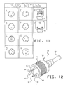
- FIGs. 11A-11J are end views of other national- standard plug configurations which can easily be incorporated into inserts such as those shown in Figs. 5-9.
- an auxiliary body such as 67′ shown in Figs. 8-9.
- Such an auxiliary body can also incorporate the other components, such as the fuse 68′ of Fig. 11I.
- an auxiliary body may be mounted at any angle with respect to insert body 51. IN Figs. 11I and 11J, for example, body 51 is perpendicular to the direction of the blades.
- FIG. 12 is an isometric view of an assembled attachment cord 70.
- one of the inserts 50 is rotated until its asymmetrically disposed sockets 52-54, Fig. 6, fit onto pins 21-23, Fig. 3.
- the insert body 51 is pushed axially into cavity 38, its frustoconical shape spreading aperture 37 until insert shoulder 65 passes shell shoulder 36, whereupon the insert is captured within cavity 38. If the length of insert body 41 is about the same as the depth of the cavity, further rearward movement after capture is prevented, and the insert is held snugly in position as though it had been molded in place.
- an attempt to disassemble connector 40 (except possibly with specially designed tools) will destroy shell 30 before releasing insert 50.
Landscapes
- Connector Housings Or Holding Contact Members (AREA)
- Coupling Device And Connection With Printed Circuit (AREA)
Applications Claiming Priority (2)
| Application Number | Priority Date | Filing Date | Title |
|---|---|---|---|
| US120063 | 1987-11-13 | ||
| US07/120,063 US4815983A (en) | 1987-11-13 | 1987-11-13 | Customizable plugs for A.C. power cords |
Publications (2)
| Publication Number | Publication Date |
|---|---|
| EP0317475A2 true EP0317475A2 (fr) | 1989-05-24 |
| EP0317475A3 EP0317475A3 (fr) | 1990-03-14 |
Family
ID=22388053
Family Applications (1)
| Application Number | Title | Priority Date | Filing Date |
|---|---|---|---|
| EP88480055A Withdrawn EP0317475A3 (fr) | 1987-11-13 | 1988-10-11 | Fiches compatibles |
Country Status (5)
| Country | Link |
|---|---|
| US (1) | US4815983A (fr) |
| EP (1) | EP0317475A3 (fr) |
| JP (1) | JPH07118345B2 (fr) |
| BR (1) | BR8805874A (fr) |
| CA (1) | CA1295387C (fr) |
Cited By (5)
| Publication number | Priority date | Publication date | Assignee | Title |
|---|---|---|---|---|
| EP0633475A3 (fr) * | 1993-07-06 | 1995-09-20 | Metrawatt Gmbh Gossen | Adapteur pour appareils électriques. |
| WO2006008072A3 (fr) * | 2004-07-15 | 2006-04-27 | Erbe Elektromedizin | Dispositif adaptateur |
| WO2006105299A1 (fr) * | 2005-03-31 | 2006-10-05 | United Parcel Service Of America, Inc. | Appareil de rattrapage de relais |
| EP1753097A3 (fr) * | 2005-08-12 | 2007-03-14 | Schneider, Hans-Peter, Prof. Dr. Dr. h. c. | Dispositif de raccordement pour un câble de bâteau |
| CN100551336C (zh) * | 2004-07-15 | 2009-10-21 | 爱尔伯电子医疗设备公司 | 适配器装置 |
Families Citing this family (37)
| Publication number | Priority date | Publication date | Assignee | Title |
|---|---|---|---|---|
| CA2032088C (fr) * | 1990-12-12 | 1995-04-18 | Jack M. Taylor | Fiche d'adaptation c.a. |
| US5214369A (en) * | 1991-12-30 | 1993-05-25 | The Charles Machine Works, Inc. | Universal battery charger |
| DE4322087C2 (de) * | 1993-07-02 | 1996-04-11 | Friemann & Wolf Gmbh | Steckernetzgerät zur Stromversorgung elektrischer Geräte |
| JP3404832B2 (ja) * | 1993-10-15 | 2003-05-12 | 住友電装株式会社 | コネクタの製造方法及びコネクタ |
| US5423690A (en) * | 1994-02-02 | 1995-06-13 | International Business Machines Corporation | Universal electrical power plug for multination use with self-setting contact pins |
| US6227888B1 (en) | 1994-02-24 | 2001-05-08 | Advanced Mobile Solutions, Inc. | Interchangeable plug device |
| US5616051A (en) * | 1995-06-21 | 1997-04-01 | Apple Computer, Inc. | A.C. mains adapters for international use |
| USD381314S (en) * | 1995-09-15 | 1997-07-22 | Asian Micro Sources, Inc. | Interchangeable plug device |
| USD376129S (en) | 1995-10-06 | 1996-12-03 | U.S. Philips Corporation | Adaptor |
| USD379003S (en) * | 1996-06-14 | 1997-04-29 | Asian Micro Sources, Inc. | Interchangeable plug device |
| USD378290S (en) * | 1996-06-14 | 1997-03-04 | Asian Micro Sources, Inc. | Interchangeable plug device |
| USD378291S (en) * | 1996-06-17 | 1997-03-04 | Asian Micro Sources, Inc. | Interchangeable plug device |
| USD382540S (en) * | 1996-06-18 | 1997-08-19 | Asian Micro Sources, Inc. | Interchangeable plug device |
| US5934096A (en) * | 1997-10-21 | 1999-08-10 | Hussmann Corporation | Wiring system for commercial refrigeration |
| US6099332A (en) * | 1998-05-26 | 2000-08-08 | The Whitaker Corp. | Connector with adaptable insert |
| US6042400A (en) * | 1998-08-25 | 2000-03-28 | International Components Corp. | Power supply housing with foldable blades |
| USD428862S (en) * | 1998-08-25 | 2000-08-01 | International Components Corp. | Folding blade assembly |
| US6220880B1 (en) * | 2000-01-27 | 2001-04-24 | Chiu-Shan Lee | Electric outlets |
| US6720527B2 (en) * | 2001-06-19 | 2004-04-13 | Illinois Tool Works, Inc. | Power cord for a welding-type power supply |
| KR20040097269A (ko) * | 2002-04-04 | 2004-11-17 | 경태 김 | 저전압 배전 회로 |
| US7465901B2 (en) | 2004-12-02 | 2008-12-16 | Illinois Tool Works Inc. | Power cord system for welding-type devices |
| US7040931B1 (en) | 2004-12-06 | 2006-05-09 | Illinois Tool Works Inc. | Power plug adapter |
| US20060213887A1 (en) * | 2005-03-24 | 2006-09-28 | Kaufman Charles L | Welding-type device power input system |
| US7175448B2 (en) * | 2005-06-29 | 2007-02-13 | Emerson Climate Technologies, Inc. | Compressor having a terminal cluster block with locking end fittings |
| US7789686B2 (en) * | 2006-02-13 | 2010-09-07 | Kyung T Kim | Receptacle with three circuit forming apertures |
| USD560963S1 (en) | 2007-03-02 | 2008-02-05 | Hamilton Beach Brands, Inc. | Blender |
| US7950842B2 (en) * | 2007-03-05 | 2011-05-31 | Hamilton Beach Brands, Inc. | Durability monitoring and improvement of a blender |
| DE102007036831A1 (de) * | 2007-08-03 | 2009-02-05 | Gerd Thiede | Prüfstecker |
| JP5050823B2 (ja) * | 2007-12-10 | 2012-10-17 | 住友電装株式会社 | コネクタ |
| TWI367601B (en) * | 2009-09-18 | 2012-07-01 | Delta Electronics Inc | Module structure of power connector |
| TW201240242A (en) * | 2011-03-18 | 2012-10-01 | Oxerer Technologies Co Ltd | Multi-in-one adapter structure |
| US8901450B2 (en) * | 2012-02-14 | 2014-12-02 | Illinois Tool Works Inc. | Consumable selection aid for a plasma cutting system |
| US9455542B2 (en) * | 2012-11-23 | 2016-09-27 | Wayne Gaither | Power cord apparatus and method of using same |
| US8876541B1 (en) * | 2013-08-12 | 2014-11-04 | Well Shin Technology Co., Ltd. | Power plug |
| US9136658B2 (en) * | 2013-08-16 | 2015-09-15 | T-Conn Precision Corporation | Cable connector with switching structure |
| TWM477712U (zh) * | 2014-01-03 | 2014-05-01 | T Conn Prec Corp | 具切換結構之改良式線纜連接器 |
| US11894642B2 (en) * | 2018-07-12 | 2024-02-06 | Illinois Tool Works Inc. | Reconfigurable welding-type power sockets and power plugs |
Family Cites Families (16)
| Publication number | Priority date | Publication date | Assignee | Title |
|---|---|---|---|---|
| US2015590A (en) * | 1930-04-23 | 1935-09-24 | Ohio Rubber Co | Terminal |
| US1932018A (en) * | 1931-07-08 | 1933-10-24 | Jr Harvey Hubbell | Electrical connecter |
| US2989719A (en) * | 1958-09-11 | 1961-06-20 | Carl J Aarlaht | Convertible attachment plugs |
| DE1640555B2 (de) * | 1967-09-25 | 1975-09-25 | The Gillette Co., Boston, Mass. (V.St.A.) | Steckvorrichtung |
| GB1515701A (en) * | 1975-02-19 | 1978-06-28 | Gillette Co | Plug for voltage adaptation |
| US4109990A (en) * | 1977-05-26 | 1978-08-29 | The Bendix Corporation | Electrical connector assembly having anti-decoupling mechanism |
| JPS5568286U (fr) * | 1978-11-02 | 1980-05-10 | ||
| DE8009606U1 (de) * | 1980-04-08 | 1980-08-07 | Braun Ag, 6000 Frankfurt | Netz-Steckvorrichtung für elektrische Geräte |
| DE3172970D1 (en) * | 1980-07-01 | 1986-01-02 | Corabelment Ag | Electrical connector with selectively available pins |
| JPS611662Y2 (fr) * | 1980-11-27 | 1986-01-20 | ||
| JPS5849589Y2 (ja) * | 1981-02-05 | 1983-11-11 | 平河電線株式会社 | 多極プラグ |
| DE3275614D1 (en) * | 1982-01-18 | 1987-04-09 | Corabelment Ag | Unitary electrical plug with multiple inlets and voltage converter |
| JPS59117083U (ja) * | 1983-01-26 | 1984-08-07 | タツタ電線株式会社 | ピンプラグ |
| GB8403294D0 (en) * | 1984-02-08 | 1984-03-14 | Rumble C S J | Electrical connectors |
| JPS62152376U (fr) * | 1986-03-18 | 1987-09-26 | ||
| GB8620776D0 (en) * | 1986-08-28 | 1986-10-08 | Adman Keland Ltd | Power transfer device |
-
1987
- 1987-11-13 US US07/120,063 patent/US4815983A/en not_active Expired - Lifetime
-
1988
- 1988-09-20 JP JP63233840A patent/JPH07118345B2/ja not_active Expired - Lifetime
- 1988-10-11 EP EP88480055A patent/EP0317475A3/fr not_active Withdrawn
- 1988-11-10 BR BR888805874A patent/BR8805874A/pt not_active IP Right Cessation
- 1988-11-10 CA CA000582793A patent/CA1295387C/fr not_active Expired - Lifetime
Cited By (8)
| Publication number | Priority date | Publication date | Assignee | Title |
|---|---|---|---|---|
| EP0633475A3 (fr) * | 1993-07-06 | 1995-09-20 | Metrawatt Gmbh Gossen | Adapteur pour appareils électriques. |
| WO2006008072A3 (fr) * | 2004-07-15 | 2006-04-27 | Erbe Elektromedizin | Dispositif adaptateur |
| CN100551336C (zh) * | 2004-07-15 | 2009-10-21 | 爱尔伯电子医疗设备公司 | 适配器装置 |
| US8623008B2 (en) | 2004-07-15 | 2014-01-07 | Erbe Elektromedizin Gmbh | Adapter device |
| WO2006105299A1 (fr) * | 2005-03-31 | 2006-10-05 | United Parcel Service Of America, Inc. | Appareil de rattrapage de relais |
| US7322849B2 (en) | 2005-03-31 | 2008-01-29 | United Parcel Service Of America, Inc. | Relay retrofit apparatus including an electrically-activated relay switch for retrofitting an electrical system |
| US7591674B2 (en) | 2005-03-31 | 2009-09-22 | United Parcel Service Of America, Inc. | Relay retrofit apparatus having a relay with two different sets of contacts, and method for retrofitting a portion of an electrical system |
| EP1753097A3 (fr) * | 2005-08-12 | 2007-03-14 | Schneider, Hans-Peter, Prof. Dr. Dr. h. c. | Dispositif de raccordement pour un câble de bâteau |
Also Published As
| Publication number | Publication date |
|---|---|
| CA1295387C (fr) | 1992-02-04 |
| JPH01149380A (ja) | 1989-06-12 |
| EP0317475A3 (fr) | 1990-03-14 |
| BR8805874A (pt) | 1989-08-01 |
| JPH07118345B2 (ja) | 1995-12-18 |
| US4815983A (en) | 1989-03-28 |
Similar Documents
| Publication | Publication Date | Title |
|---|---|---|
| US4815983A (en) | Customizable plugs for A.C. power cords | |
| JPS603498Y2 (ja) | 非平面配列状の導体を有するコ−ドを終端させるためのモジユ−ル式プラグ | |
| US5915984A (en) | Modular electrical outlet and connector assembly | |
| US4445745A (en) | Electrical connectors for coaxial and two-wire cables | |
| US7458814B2 (en) | Twist-check socket and electronic articles equipped with the same | |
| JP3475331B2 (ja) | 電気接続装置 | |
| US4891017A (en) | Socket connector with pin aligning housing | |
| EP2755283B1 (fr) | Connecteur configurable par l'utilisateur | |
| US4900270A (en) | Cable adaptor assembly | |
| US20130237095A1 (en) | Electrical connector with a push-in type contact | |
| US20040077224A1 (en) | Combination terminal device | |
| US5035646A (en) | Flush mounted receptacle and plug with pin and sleeve type contacts | |
| US3020516A (en) | Electrical connector body and cap construction with improved conductor securing means | |
| US4394057A (en) | Double-molded electrical end fitting assembly | |
| US3495205A (en) | Convertible plug | |
| US4789361A (en) | Fused cigarette lighter receptacle and adaptor plug assemblies | |
| CA2083358C (fr) | Fiche pour cable a autoregulation | |
| US12119594B1 (en) | Plug assembly for power cord | |
| GB2104312A (en) | Coaxial cable connector | |
| US6464519B1 (en) | Electrical extension cord with convertible plug and accommodating receptacle | |
| JPH0419739Y2 (fr) | ||
| US3029406A (en) | Connector | |
| US4108525A (en) | Hermaphroditic edgeboard connectors | |
| EP3514893A2 (fr) | Connecteur pour outils | |
| US6179669B1 (en) | Molded receptacle for a daisy chain power cord assembly |
Legal Events
| Date | Code | Title | Description |
|---|---|---|---|
| PUAI | Public reference made under article 153(3) epc to a published international application that has entered the european phase |
Free format text: ORIGINAL CODE: 0009012 |
|
| AK | Designated contracting states |
Kind code of ref document: A2 Designated state(s): BE CH DE ES FR GB IT LI NL SE |
|
| 17P | Request for examination filed |
Effective date: 19890906 |
|
| PUAL | Search report despatched |
Free format text: ORIGINAL CODE: 0009013 |
|
| AK | Designated contracting states |
Kind code of ref document: A3 Designated state(s): BE CH DE ES FR GB IT LI NL SE |
|
| 17Q | First examination report despatched |
Effective date: 19911219 |
|
| STAA | Information on the status of an ep patent application or granted ep patent |
Free format text: STATUS: THE APPLICATION IS DEEMED TO BE WITHDRAWN |
|
| 18D | Application deemed to be withdrawn |
Effective date: 19920630 |