EP0317517A2 - Zusammensetzbare Niederspannungsschalttafel für ein modulares Gerät in einem isolierten Gehäuse - Google Patents
Zusammensetzbare Niederspannungsschalttafel für ein modulares Gerät in einem isolierten Gehäuse Download PDFInfo
- Publication number
- EP0317517A2 EP0317517A2 EP88830380A EP88830380A EP0317517A2 EP 0317517 A2 EP0317517 A2 EP 0317517A2 EP 88830380 A EP88830380 A EP 88830380A EP 88830380 A EP88830380 A EP 88830380A EP 0317517 A2 EP0317517 A2 EP 0317517A2
- Authority
- EP
- European Patent Office
- Prior art keywords
- modular
- box
- module
- terminal blocks
- electrical panels
- Prior art date
- Legal status (The legal status is an assumption and is not a legal conclusion. Google has not performed a legal analysis and makes no representation as to the accuracy of the status listed.)
- Withdrawn
Links
Images



Classifications
-
- H—ELECTRICITY
- H02—GENERATION; CONVERSION OR DISTRIBUTION OF ELECTRIC POWER
- H02B—BOARDS, SUBSTATIONS OR SWITCHING ARRANGEMENTS FOR THE SUPPLY OR DISTRIBUTION OF ELECTRIC POWER
- H02B1/00—Frameworks, boards, panels, desks, casings; Details of substations or switching arrangements
- H02B1/26—Casings; Parts thereof or accessories therefor
- H02B1/40—Wall-mounted casings; Parts thereof or accessories therefor
- H02B1/42—Mounting of devices therein
-
- H—ELECTRICITY
- H02—GENERATION; CONVERSION OR DISTRIBUTION OF ELECTRIC POWER
- H02B—BOARDS, SUBSTATIONS OR SWITCHING ARRANGEMENTS FOR THE SUPPLY OR DISTRIBUTION OF ELECTRIC POWER
- H02B1/00—Frameworks, boards, panels, desks, casings; Details of substations or switching arrangements
- H02B1/20—Bus-bar or other wiring layouts, e.g. in cubicles, in switchyards
- H02B1/202—Cable lay-outs
Definitions
- the present invention relates to a composable low-voltage electrical panel structure, of the segregated bus-bar type, in particular for modular electrical apparatus and automatic switches and current-limit switches, arranged in insulating housings or boxes and of high rated current.
- this electrical panels are made by substantially low-production methods, which use scarcely flexible base components, that is components which can not be easily adapted to a broad range of requirements and which, moreover, are to be assembled by highly skilled operators with long times for the installation and calibration steps, which negatively affects the operating and cost characteristics of the finished electrical panel.
- the task of the present in vention is to provide a system of base electrical modules which can be obtained starting from metal sheet elements, insulating material and copper elements, which affords the possibility of easily assembling a broad range of electrical panels, in particular of the low-voltage type, by using conventional tools, such as screw-drivers, cutting and/or the like devices, and, in particular, with a very reduced number of component codes, and without the need of carrying out adjusting and/or calibrating operations during the assembling steps.
- a main object of the present invention is to provide a range of modular elements, for making low voltage electrical panels, which afford the possibility of constructing electrical panels meeting a broad range of protection requirements, from usual protection requirements to tight protection requirements.
- Another object of the present invention is to provide modular elements for making electrical panels which may be easily and quickly assembled and which have standardized size so as to afford the possibility of making at least three types of columns.
- Yet another object of the present inven tion is to provide a range of modular elements, for making electrical panels, which afford the possibility of pre-assembling modular switches by using conductor wires of standardized lengths,which are precut and electrically terminated by means of automatic machines, with the possibility of adopting wire lengths within a very broad range.
- Yet another object of the present invention is to provide an electrical component system for making electrical panels in which the bus-bars, the connecting bars and the branching bars are all of standardized type and related to the specific type of switch to be used jointly with the related supporting base.
- Yet another object of the present invention is to provide a modular element system, for making electrical panels, which afford the possibility of displacing the bus-bar system from a column to another column, with a minimum number of product code types (in particular only three types), with a segregated bus-bar systems and with standardized sleeves and bus-bar supporting assemblies.
- Yet another object of the present invention is to provide a modular elements system for making electrical panels the single elements of which can be easily associated, by means of fixed mounting members, so as to completely eliminate any needs of carrying out complex adjusting operation, during the assembling steps of said electrical panel.
- a modular element system for making electrical panels for particular low-voltage electrical panels, characterized in that it comprises a simple-column module, with top and bottom output terminal blocks, a module including a simple upright column and side terminal blocks, for modular electrical appliances, with a direct coupling to the boxed-in switches, and a module having a double-upright column for boxed-switches on a double row.
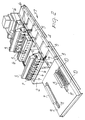
- Figure 1 illustrates a perspective view of a column module which forms one of the main modules of the modular system for making electrical panels according to the invention.
- this module which has been overally indicated at the reference number 1 and which, in Figure 1, is shown by a broken-away view, comprises a plurality of supporting box-like elements 2.
- Each box-like element 2, having a substantially parallelepipedal configuration, is made starting from a metal sheet, and supports electrical appliances, indicated generally at the reference number 3, which, in particular can consist of boxed- in electrical switches or breakers.
- said electrical switches or breakers 3 can be prewired by using conductor wires F of standardized length, which have been precut and electrically terminated by means of automatic machines of conventional types (and not shown).
- the invention firstly provides the possibility of automatizing the wiring and assembling operations of the electrical appliances mounted on the supporting column 1.
- the column module 1 is shown mounted on a base supporting plate 4, also made of a sheet metal.
- the conductor wires F are protected by cover modules, for example made of PVC, and which have been indicated overally at the reference numbers 5 and 5′.
- the mentioned cover modules 5 and 5′ can be affixed by means of any known systems, for example by using screws and the like, in a removable way, to the base supporting plate 4 and box-like element 2.
- each supporting box-like body 2 is provided with a sup porting element 6 including a standardized guide and rail 6′ and an edge 6 ⁇ of sheet metal for affixing the wire covering module 5′; the supporting element 6 is provided with a plurality of throughgoing holes therein annular elements are engaged, for example made of a resilient material such as rubber and the like, for protecting the conductor wires F.
- the electrical appliances 3 are supported on the supporting box-like elements or bodies 2 by means of standardized rail guides 6′ which are removably affixed to the support member 6, in turn coupled removably to the top face of each supporting box-like body 2, for example by means of screws, so as to afford the possibility of removably affixing the individual electrical appliances and/or breakers 3.
- the conductor wires F, coming from the mentioned appliances 3, and protected by the plastics material box-like bodies 5 and 5′ arrive at the bottom terminal blocks 7 and 8.
- terminal blocks 7 and 8 in particular, are supported by a metal base plate 9, of box-like shape, the top face of which is provided with a plurality of throughgoing slots 10 for affixing in an adjustable way thereon rail elements 11 and 11′ for adjustably supporting the terminal blocks 8.
- the column 1 is provided with a single bottom terminal block; however, it should be apparent that, if required, said column 1 may also be provided with a top terminal block or with both a bottom and a top terminal block.
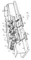
- FIG. 3 shows a further column module, indicated generally at the reference number 10′, which is substantially similar to the column module 1.
- a main difference of the above column modules consists of the fact that the terminal blocks 7′ and 8′ are mounted laterally at two different levels.
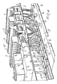
- this is a perspective view illustrating a further column module 10 ⁇ , in a partially disassembled condition, in order to clearly illustrate the conductor bus-bar system.
- this conductor bus-bar system which, as particularly shown in Figures 6 A, is insulated from the base supporting plate 15 by means of insulating members 16, and is affixed to the insulating members by means of modular metal elements 16′ (Fig. 6B) 16 ⁇ (Fig. 6C) 16′′′ (Fig. 6D) comprises conductor bus-bar elements 18, of substantially L or C shape, for coupling the boxed-in appliances, and conductor bus-bar elements 18′ for coupling with insulated conductor wires 18 ⁇ .
- bus-bars are mutuallyly coupled, by means of suitable coupling elements, such as the bolt and nut assemblies 19 (Fig. 6E).
- the coupling and branching bus-bars,for several types and rated values of boxed-in breakers will be in this way standardized,and will constitute a part of the code or product type related to the type of the breaker or switch,jointly with the related supporting element and branching system included.
- bus-bar system it will be possible to displace or transfer the bus bar system from a column to another column,by means of only three product types,the bus bars having a segregated arrangement,and by means of three different length sleeves which will use standardized bus bars and bar holders as well as the conductor element of fig.6F.
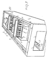
- Figure 5 illustrates,by a perspective view, and in a partially broken away manner, a column module according to the present invention which is housed in a box-like body 20 provided for forming the holding body of the electrical panel which,in figure 5,has been shown devoid of the closure doors.
- the modular system according to the invention affords the possibility of making electrical panels having the following main features:
- the premounted column will be inserted the end electrical terminations and sides and the electrical panel will be fitted with the covering plates and doors.
- the variation is obtained by only changing the type of support. This variation may be completed by a single fixed drawer,for a motor starting of the M.C.C. type,with removable appliance bearing plate with the panel under voltage,by preliminary detaching the wires from the terminal block and at the output of the line protecting fuses.
Landscapes
- Engineering & Computer Science (AREA)
- Power Engineering (AREA)
- Distribution Board (AREA)
- Casings For Electric Apparatus (AREA)
Applications Claiming Priority (2)
| Application Number | Priority Date | Filing Date | Title |
|---|---|---|---|
| IT2198787 | 1987-09-22 | ||
| IT8721987A IT1226062B (it) | 1987-09-22 | 1987-09-22 | Struttura di quadro elettrico a bassa tensione componibile a sbarre segregate, in particolare per apparecchiature modulari per interuttori automatici e limitatori di corrente in scatola isolante ad alta corrente nominale. |
Publications (2)
| Publication Number | Publication Date |
|---|---|
| EP0317517A2 true EP0317517A2 (de) | 1989-05-24 |
| EP0317517A3 EP0317517A3 (de) | 1989-10-18 |
Family
ID=11189829
Family Applications (1)
| Application Number | Title | Priority Date | Filing Date |
|---|---|---|---|
| EP88830380A Withdrawn EP0317517A3 (de) | 1987-09-22 | 1988-09-20 | Zusammensetzbare Niederspannungsschalttafel für ein modulares Gerät in einem isolierten Gehäuse |
Country Status (2)
| Country | Link |
|---|---|
| EP (1) | EP0317517A3 (de) |
| IT (1) | IT1226062B (de) |
Cited By (2)
| Publication number | Priority date | Publication date | Assignee | Title |
|---|---|---|---|---|
| WO2006048756A1 (en) * | 2004-11-05 | 2006-05-11 | Abb Technology Ltd | A mounting system for a switchboard and a method for assembling the switchboard |
| FR3077168A1 (fr) * | 2019-01-24 | 2019-07-26 | Izyx Systems | Coffret électrique |
Family Cites Families (4)
| Publication number | Priority date | Publication date | Assignee | Title |
|---|---|---|---|---|
| US3832604A (en) * | 1973-04-09 | 1974-08-27 | Gen Electric | Electrical protective panel assembly |
| US4292661A (en) * | 1979-09-26 | 1981-09-29 | Thermo King Corporation | Power and control system arrangement for transport refrigeration unit |
| NL8203760A (nl) * | 1982-09-28 | 1984-04-16 | Electrotechnische Ind Van Der | Goot voor het onderbrengen van de bedrading in montagekasten van elektrische installatie. |
| US4631634A (en) * | 1985-02-25 | 1986-12-23 | General Electric Company | Lighting circuit breaker panelboard modular assembly |
-
1987
- 1987-09-22 IT IT8721987A patent/IT1226062B/it active
-
1988
- 1988-09-20 EP EP88830380A patent/EP0317517A3/de not_active Withdrawn
Cited By (3)
| Publication number | Priority date | Publication date | Assignee | Title |
|---|---|---|---|---|
| WO2006048756A1 (en) * | 2004-11-05 | 2006-05-11 | Abb Technology Ltd | A mounting system for a switchboard and a method for assembling the switchboard |
| CN101069330B (zh) * | 2004-11-05 | 2010-06-09 | Abb技术有限公司 | 配电板的安装系统和装配该配电板的方法 |
| FR3077168A1 (fr) * | 2019-01-24 | 2019-07-26 | Izyx Systems | Coffret électrique |
Also Published As
| Publication number | Publication date |
|---|---|
| IT1226062B (it) | 1990-12-10 |
| IT8721987A0 (it) | 1987-09-22 |
| EP0317517A3 (de) | 1989-10-18 |
Similar Documents
| Publication | Publication Date | Title |
|---|---|---|
| EP3667844B1 (de) | Leiter für ein stromverteilungssystem | |
| US6870103B1 (en) | Bus joint cover assembly | |
| CN102037623B (zh) | 用于低电压配电的封闭母线系统 | |
| US4962443A (en) | Improved residential loadcenter | |
| EP0325371A1 (de) | Verbesserungen in Bezug auf Verbrauchereinheiten | |
| US2351942A (en) | Panel-board construction | |
| KR20170033720A (ko) | 부스바용 포크형 커넥터 및 이와 결합된 절연결합체 | |
| EP3926774B1 (de) | Sammelschienenplatte | |
| CN106877186A (zh) | 固定的竖直配电母线 | |
| US4931902A (en) | Bushbar barrier protective members | |
| EP3163694B1 (de) | Elektrisch isolierende abdeckung für anschlussanordnung | |
| KR20070018130A (ko) | 조립식 분전반 | |
| US4931903A (en) | Loadcenter mounting rail adapter | |
| EP3817025B1 (de) | Leiteranordnung für ein stromverteilungssystem | |
| US7121856B2 (en) | Device for connection of busbars to equipment of an electrical switchboard | |
| EP0909472B1 (de) | Modulare schrankanordnung zur steuerung elektrischer geräte, insbesondere für motoren | |
| EP1346387B1 (de) | Stecksockel für schutzschalter | |
| EP0757367B1 (de) | Schaltsystem mit Anschlussklemmenmodulen | |
| US7224577B2 (en) | Mounting plate system | |
| EP0319483A2 (de) | Modulare elektrische Niederspannungsschalttafel für ein modulares elektrisches Gerät | |
| US10297985B2 (en) | Modular electrical devices and methods for assembling and mounting the same | |
| SU1316064A1 (ru) | Шкаф комплектного распределительного устройства | |
| US20260024965A1 (en) | Insulation barrier for switchgear assembly and method for assembling a switchgear | |
| EP0353202A2 (de) | Modulares Elementesystem zur Herstellung elektrischer Schalttafeln, insbesondere für niedrige Spannungen | |
| CN112736534B (zh) | 用于配电系统的导体组件 |
Legal Events
| Date | Code | Title | Description |
|---|---|---|---|
| PUAI | Public reference made under article 153(3) epc to a published international application that has entered the european phase |
Free format text: ORIGINAL CODE: 0009012 |
|
| AK | Designated contracting states |
Kind code of ref document: A2 Designated state(s): BE CH DE ES FR GB LI NL SE |
|
| PUAL | Search report despatched |
Free format text: ORIGINAL CODE: 0009013 |
|
| AK | Designated contracting states |
Kind code of ref document: A3 Designated state(s): BE CH DE ES FR GB LI NL SE |
|
| 17P | Request for examination filed |
Effective date: 19900319 |
|
| 17Q | First examination report despatched |
Effective date: 19911114 |
|
| STAA | Information on the status of an ep patent application or granted ep patent |
Free format text: STATUS: THE APPLICATION HAS BEEN WITHDRAWN |
|
| 18W | Application withdrawn |
Withdrawal date: 19930306 |