EP0317559B1 - Mobile tragevorrichtung - Google Patents
Mobile tragevorrichtung Download PDFInfo
- Publication number
- EP0317559B1 EP0317559B1 EP87904548A EP87904548A EP0317559B1 EP 0317559 B1 EP0317559 B1 EP 0317559B1 EP 87904548 A EP87904548 A EP 87904548A EP 87904548 A EP87904548 A EP 87904548A EP 0317559 B1 EP0317559 B1 EP 0317559B1
- Authority
- EP
- European Patent Office
- Prior art keywords
- support device
- mobile support
- frame
- frame sections
- wheels
- Prior art date
- Legal status (The legal status is an assumption and is not a legal conclusion. Google has not performed a legal analysis and makes no representation as to the accuracy of the status listed.)
- Expired - Lifetime
Links
Images













Classifications
-
- A—HUMAN NECESSITIES
- A61—MEDICAL OR VETERINARY SCIENCE; HYGIENE
- A61H—PHYSICAL THERAPY APPARATUS, e.g. DEVICES FOR LOCATING OR STIMULATING REFLEX POINTS IN THE BODY; ARTIFICIAL RESPIRATION; MASSAGE; BATHING DEVICES FOR SPECIAL THERAPEUTIC OR HYGIENIC PURPOSES OR SPECIFIC PARTS OF THE BODY
- A61H3/00—Appliances for aiding patients or disabled persons to walk about
- A61H3/04—Wheeled walking aids for patients or disabled persons
-
- A—HUMAN NECESSITIES
- A61—MEDICAL OR VETERINARY SCIENCE; HYGIENE
- A61G—TRANSPORT, PERSONAL CONVEYANCES OR ACCOMMODATION SPECIALLY ADAPTED FOR PATIENTS OR DISABLED PERSONS; OPERATING TABLES OR CHAIRS; CHAIRS FOR DENTISTRY; FUNERAL DEVICES
- A61G5/00—Chairs or personal conveyances specially adapted for patients or disabled persons, e.g. wheelchairs
-
- A—HUMAN NECESSITIES
- A61—MEDICAL OR VETERINARY SCIENCE; HYGIENE
- A61G—TRANSPORT, PERSONAL CONVEYANCES OR ACCOMMODATION SPECIALLY ADAPTED FOR PATIENTS OR DISABLED PERSONS; OPERATING TABLES OR CHAIRS; CHAIRS FOR DENTISTRY; FUNERAL DEVICES
- A61G5/00—Chairs or personal conveyances specially adapted for patients or disabled persons, e.g. wheelchairs
- A61G5/10—Parts, details or accessories
- A61G5/1094—Tables, working plates or trays
-
- A—HUMAN NECESSITIES
- A61—MEDICAL OR VETERINARY SCIENCE; HYGIENE
- A61G—TRANSPORT, PERSONAL CONVEYANCES OR ACCOMMODATION SPECIALLY ADAPTED FOR PATIENTS OR DISABLED PERSONS; OPERATING TABLES OR CHAIRS; CHAIRS FOR DENTISTRY; FUNERAL DEVICES
- A61G5/00—Chairs or personal conveyances specially adapted for patients or disabled persons, e.g. wheelchairs
- A61G5/10—Parts, details or accessories
- A61G5/12—Rests specially adapted therefor, e.g. for the head or the feet
- A61G5/125—Rests specially adapted therefor, e.g. for the head or the feet for arms
-
- A—HUMAN NECESSITIES
- A61—MEDICAL OR VETERINARY SCIENCE; HYGIENE
- A61G—TRANSPORT, PERSONAL CONVEYANCES OR ACCOMMODATION SPECIALLY ADAPTED FOR PATIENTS OR DISABLED PERSONS; OPERATING TABLES OR CHAIRS; CHAIRS FOR DENTISTRY; FUNERAL DEVICES
- A61G5/00—Chairs or personal conveyances specially adapted for patients or disabled persons, e.g. wheelchairs
- A61G5/10—Parts, details or accessories
- A61G5/12—Rests specially adapted therefor, e.g. for the head or the feet
- A61G5/128—Rests specially adapted therefor, e.g. for the head or the feet for feet
-
- A—HUMAN NECESSITIES
- A61—MEDICAL OR VETERINARY SCIENCE; HYGIENE
- A61H—PHYSICAL THERAPY APPARATUS, e.g. DEVICES FOR LOCATING OR STIMULATING REFLEX POINTS IN THE BODY; ARTIFICIAL RESPIRATION; MASSAGE; BATHING DEVICES FOR SPECIAL THERAPEUTIC OR HYGIENIC PURPOSES OR SPECIFIC PARTS OF THE BODY
- A61H3/00—Appliances for aiding patients or disabled persons to walk about
- A61H2003/002—Appliances for aiding patients or disabled persons to walk about with attached or incorporated article carrying means
- A61H2003/004—Trays
-
- A—HUMAN NECESSITIES
- A61—MEDICAL OR VETERINARY SCIENCE; HYGIENE
- A61H—PHYSICAL THERAPY APPARATUS, e.g. DEVICES FOR LOCATING OR STIMULATING REFLEX POINTS IN THE BODY; ARTIFICIAL RESPIRATION; MASSAGE; BATHING DEVICES FOR SPECIAL THERAPEUTIC OR HYGIENIC PURPOSES OR SPECIFIC PARTS OF THE BODY
- A61H3/00—Appliances for aiding patients or disabled persons to walk about
- A61H3/04—Wheeled walking aids for patients or disabled persons
- A61H2003/046—Wheeled walking aids for patients or disabled persons with braking means
-
- A—HUMAN NECESSITIES
- A61—MEDICAL OR VETERINARY SCIENCE; HYGIENE
- A61H—PHYSICAL THERAPY APPARATUS, e.g. DEVICES FOR LOCATING OR STIMULATING REFLEX POINTS IN THE BODY; ARTIFICIAL RESPIRATION; MASSAGE; BATHING DEVICES FOR SPECIAL THERAPEUTIC OR HYGIENIC PURPOSES OR SPECIFIC PARTS OF THE BODY
- A61H2201/00—Characteristics of apparatus not provided for in the preceding codes
- A61H2201/16—Physical interface with patient
- A61H2201/1602—Physical interface with patient kind of interface, e.g. head rest, knee support or lumbar support
- A61H2201/1614—Shoulder, e.g. for neck stretching
-
- A—HUMAN NECESSITIES
- A61—MEDICAL OR VETERINARY SCIENCE; HYGIENE
- A61H—PHYSICAL THERAPY APPARATUS, e.g. DEVICES FOR LOCATING OR STIMULATING REFLEX POINTS IN THE BODY; ARTIFICIAL RESPIRATION; MASSAGE; BATHING DEVICES FOR SPECIAL THERAPEUTIC OR HYGIENIC PURPOSES OR SPECIFIC PARTS OF THE BODY
- A61H2201/00—Characteristics of apparatus not provided for in the preceding codes
- A61H2201/16—Physical interface with patient
- A61H2201/1602—Physical interface with patient kind of interface, e.g. head rest, knee support or lumbar support
- A61H2201/1628—Pelvis
- A61H2201/1633—Seat
Definitions
- the present invention relates to a mobile support device, according to the first part of claims 1 and 26, respectively.
- a mobile support device is disclosed in the documents US-A-3788695 and US-A-1 611 807, respectively.
- walkers are available providing bodily support to the patients.
- Such devices are often large and bulky and require the patient to be entrapped within the structure, resulting in a mobility aid which, although assisting the patient, is conspicuous and therefore detrimental to the patients emotional well-being.
- U.S. patent 1,116,807 to Bergh illustrates an exercising device which has a castered frame, a harness that supports the patient in a standing position and a retractable seat.
- U.S. Patent Specification No. 5892,282 to Duke also illustrates an exercising device with a castered frame and a retractable seat. However, in both cases, the frame is bulky leading the device to be unsuitable to many patients with limited strength.
- U.S. Patent 3,788,695 to Salem illustrates a sitting/standing Table/walker combination that has the seat and back portions of a chair and a wheeled undercarriage with front and rear caster wheels.
- a tray is provided to secure the patient in the chair.
- Salem's device is also provided with a base plate to restrain the feet of the patient.
- This chair is generally unsuitable for many patients with limited strength since its undercarriage cannot offer the degree of directional control needed for such patients if they are to mobile on their own.
- the invention provides a mobile support device having the features set out in the characterising portion of claims 1 and 26, respectively.
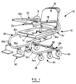
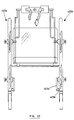
- a mobility device 10 is shown in the form of a chair having a frame 12 which supports seat 14 and a back rest 16, with the seat being inclined at approximately six degrees from the horizontal axis, and the back rest 16 inclined 15 degrees from the vertical axis.
- the chair has a pair of arms 18, 20 the former being pivotal and the latter being retractable as will be described.
- a tray 22 is mounted on the front of the arms 18, 20 and provides a working surface as well as a protective gate and hand grip.
- a carrying hamper 23 hangs from the arm 20 for carrying magazines or other articles.
- a wheel assembly 24 is provided on the bottom of the chair which is controlled by a pair of braking handles 26 which activate a braking mechanism 28 as will be described.
- a pair of adjustable foot rests 30 are mounted on the frame 12 as will be described, with restraint being provided to the user by a seat belt 32 extending from the seat. As well, the seat is pivotable and height adjustable as will be later explained.
- the frame is formed from left and right frame sections 34, 36 both being of an "S"-shaped configuration.
- Each of the left and right frame sections have a lower horizontal portion 34a, 36a to support the wheel assembly, a lower corner portion 34b, 36b to support the foot rests 30, a middle portion 34c, 36c to support the seat 14 and back rest 16, and an upper portion 34d, 36d to support the tray 22 and also to form the arms 18, 20 of the chair.
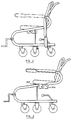
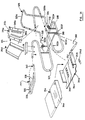
- the middle portion 34c, 36c serves as a location for frame disassembly, as shown in Figure 3. This is provided by way of the middle portion being formed from two parts, a first segment, for example 34e, having a swaged end of reduced diameter for telescoping engagement with the end of a second segment 34f.
- each of the arms 18, 20 is also provided with a pair of arm rests 42, while the tray 22 is pivotally connected to the left arm 18 and releasably positioned on the right arm 20.
- the lateral edges 22a of the tray are concave thereby providing sufficient area for a working surface while enabling the patient to grip the central region of the tray 22 with his hands.
- the right arm 20 is easily retractable, and is formed from first and second right arm portions 20a, 20b the first portion 20a having a swaged end region for telescoping engagement with the end of the second right arm portion 20b.
- a restraint mechanism 44 is provided in the first right arm portion 40a and is seen as a ball 44a nested in a hole 20c and biased therein by way of a compression spring, 44b with the ball extending from the hole so as to extend into a hole 20d formed in the second right hand portion 20b.
- the left arm 18 While the right arm 20 is retractable, the left arm 18 is pivotal between a usable position and a storage position.
- the left arm 18 has a first left arm portion 18a pivotally connected to a second left arm portion 18a at a pivot connection identified at 45.
- the end of the first left arm portion 38a is collapsed to form a substantially "U"-shaped cross-section.
- the first left arm portion 18a is pivotally connected to the second left arm portion 18b by way of an extensible pivot member 46 extending through co-axial bores 18c, 18d formed in the first and second left arm portions 18a, 18b respectively.
- the extensible pivot member 46 is formed from a cylinder element 46a closed at one end by a first head 46b with the other end having a bore 46c extending there-through.
- a piston 46d is slidably engaged with the inner surface of the cylinder element 46a and is joined to a shaft 46e which extends through the bore 46c, with the free end of the shaft terminating at a second head 46f.
- a compression spring 46g is located within the cylinder element 46b to bias the piston 46d against the first head 46b, such that rotation of the first left arm portion 38a causes separation thereof from the second left arm portion 38b, and causing the pivot member 46 to extend through the travel of the piston 46d along the cylinder element 46a against the spring 46g.
- the pivot connection between the first and second left arm portions 18a, 18b and the pivot connection between the tray 22 and the first left arm portion 18a enables the left arm 18 to be rotated to a convenient storage position as demonstrated in Figures 2, 10, 12 and 13.
- the tray 22 is first rotated to a vertical position as seen by the arrow "A”.
- the first left arm portion is then rotated to an upper vertical position as seen by arrow "B”.
- the tray being returned to its original position relative to the first left arm portion as seen by arrow "C”.
- the arm is rotated to a lower storage position as seen by the arrow "D".
- the configuration embodied in the left arm 18 enables the patient to store the tray thereby providing the patient with the capability of sitting at a table, or of accessing the chair from the side.
- the first right arm portion 20a is easily retractable by depressing the ball 44a through the hole 20d and subsequently removing the swaged end of the first right arm portion 20a from the second right arm portion 20b.
- FIG. 1 Another particular feature of the chair 10 is the wheel assembly 24 as seen in Figure 1 which is coupled to the lower horizontal portions 34a, 36a of the left and right frame sections 34, 36.
- Three wheels, for example wheels 48, 50, 53 are used on each of the lower horizontal portions, for example 34a, the front and rear wheels 48, 50 thereof providing a swivel movement with respect to the lower horizontal portion 34a.
- the intermediate wheel 53 on the other hand is constrained to rotation about an axis perpendicular to the lower horizontal portion 34a. In this configuration, the intermediate wheels 53 prevent lateral displacement of the chair relative to the floor while permitting increased stability and improved directional tracking, as well as the ability to rotate about a fixed point.
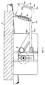
- the braking assembly 28 is shown in detail in Figure 8.
- the brakes are manually controlled by braking levers 26 which extend upwardly and forwardly from slots 54 formed in the rear of the lower horizontal portions 34a, 34b.
- Each of the levers 26 are coupled to a first link 56 which is fixed to one end of a pivot rod 58 defining a pivot axis "E", which in turn is rotatably mounted at both ends to the horizontal portions 34a, 34b.
- the pivot rod 58 conveniently extends in a concealed manner within a spanner member 60 joining the left and right lower horizontal portions 34a, 34b.
- the first link 56 is pivotally connected to one end 62a of a second link 62 at a pivot identified at "F" which extends along the inner cavity of the lower horizontal portion 34a, with the opposite end 62b being pivotally connected to one end 64a of a braking link 64.
- the lower portion of the braking link extends downwardly to a pivot pin 66 on which the braking link pivots relative to the lower horizontal portion.
- the braking link extends past the pivot pin and outward from a slot 68 formed in the lower region of the horizontal portion 34a.
- Joined to the other end 64b of the braking link 64 is a brake pad 69 of an arcuate shape so as to contact the floor contacting surface 53a of the intermediate wheel 53.
- the braking assembly 28 provides simultaneous braking of both left and right intermediate wheels 53 by rotation of either braking lever 26.
- the pivot points are selected in the first link such that the pivot point "F" of the second link is “over-center” with respect to the pivot axis "E” of the pivot rod 58.
- the braking assembly 28 provides a self-locking mechanism whereby the braking lever 26 is rotated toward contact with the rear edge of the slot 54. This corresponds to a point where the pivot point "F” is located above axis "E", thereby causing the reaction force, exerted by the wheel 54 and transmitted through the mechanism 28, to maintain the lever 26 in the locked position against the rear edge of the slot.
- the braking mechanism 28 is capable of providing a constant light braking force to the middle wheels for a controlled substantially unaccelerated travel down an incline.
- This is provided by an arcuate bracket 70 which is fixed to the lower horizontal portion 34a of the frame adjacent to the central region of a brake lever 26.
- the bracket 70 has a number of notches 70a formed therein to enable the lever 26 to be locked in a particular orientation so as to provide a constant braking force against the intermediate wheel 53.
- the extent of rotation of the lever 26 to maintain substantially unaccelerated travel increases with the degree of incline being traversed.
- the pivot rod 66 may be located on the frame 53b of the wheel rather than on the lower horizontal portion 34a, thereby providing relatively shorter distance of travel of the brake pad 69.
- the chair is also provided with a seat 14 which is pivotal and height adjustable by way of a height adjustment mechanism 74 illustrated in Figures 6 and 7.
- the seat is pivotally mounted via a pair of first support blocks 76 to a tubular shaft 78, the shaft being held at each end by a second support element 80.
- Adjacent the second support element 80 is a rack element 82 of a rack and pinion arrangement, the pinion 84 being fixed to a rod 86 which extends through a slot 80a formed in the second support element 80.
- Both the second support element 80 and the rack element 82 are fixed to a transverse frame element 88.
- a plate element 90 Positioned adjacent the second support element is a plate element 90 having a centrally located slot 104, through which the rod 86 extends.
- a pair of guides 92 extend downwardly along the inner surface of the plate so as to engage with the front and rear edges 80b, 80c of the second support element 80.
- Fixed to the end of the rod 86 is a knob 94 for rotation of the rod 86 and accordingly the pinion 84 along the rack element 82.
- the region of the rod 86 between the knob 94 and the plate 90 is threaded to engage threadably with a release latch 96, which releasably maintains the rod 86 in position.
- the height adjustment mechanism provides facilitated adjustment of the seat 14 relative to the frame 12, by way of rotating the release latch 96 and subsequently turning the knob 94. This causes relative displacement between the rack element 82 and the pinion 84, and results in the support element 80 travelling along the guide 92.
- a further mechanism is provided on the seat to dampen sudden rotations of the seat relative to the shaft.
- an air cylinder 98 is joined to the central region of the rear of the seat 14 and to a support frame 100 which includes an arm 100a extending rearwardly from the transverse frame member 88 and a brace 100b joining the arm 100a with the shaft 78.
- FIG. 6 Another embodiment is shown in dashed lines in Figure 6 wherein the seat is pivotally mounted on shaft 86 by way of support blocks 102 in lieu of support blocks 76 and shaft 78.
- the rack element 82 and the support block 80 are fixedly mounted to plate element 90 while shaft 86 is displaced relative to plate 90 by extending through the slot 104, thereby eliminating the need for guides 92 and transverse frame element 88.
- a support frame 106 is pivotally mounted on shaft 86 in lieu of support frame 100.
- support frame 106 includes a support block 107 pivotally mounted on the shaft 86 adjacent each pinion element 84.
- Projections 108 extend from the upper and lower portions of support block 107, adjacent to but not contacting the teeth of pinion 84, and extend through the slots 80a. In this manner, support block 107 displaces in concert with the rod 86 but does not rotate therewith. Extending rearwardly from each of the support blocks 107 is a frame member 109 which terminates at a junction with a frame member 109a which extends toward connection with the air cylinder 98.
- a tension spring 97 is located adjacent the air cylinder 98 to bias the seat to its rearwardly inclined position.
- a rotation limit device 99 is located adjacent the air cylinder 98 to restrict the rearward and forward rotation of the seat to the desired six degrees with respect to the horizontal.
- the limit device includes an elongate element 99a having a slot 99b which is connected to the rear portion of the seat.
- a member 99c with a pin 99d is coupled to the arm 100a.
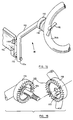
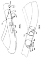
- the chair is also provided with adjustable foot rest 30 as are shown in detail in Figures 14 and 15.
- the foot rest 30 includes an angular member 110 having a shaft 112 connected to one end 110a.
- a foot pad 114 is pivotally connected to the shaft 112 for movement between a horizontal position and a vertical position.
- Magnets 116 are further provided both on the foot pad 114 and the angular member 110 to maintain the foot pad 114 in a vertical position.
- the angular member is in turn joined to the lower corner portion 34b by a wing nut 115, and maintained in a given orientation by a pair of interconnecting discs 116, 118.
- each of the discs has transversely extending triangular teeth 120 which mesh upon engagement of the discs 116, 118, with the disc 116 being fixed to the angular member, and the other disc 118 being fixed to the lower corner portion 34b.
- the discs 118, 116 are also respectively provided with a pin 122 and recess 124 as shown in Figure 15 to enable inter-engagement of the discs within predetermined limits, thereby preventing the foot rest 30 from contacting the floor, and interferring with the mobility of the chair.
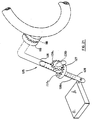
- FIG. 21 An alternative foot rest 125 is shown in Figure 21 wherein a right angled member 126 extends from the inter-engaged discs 116, 118 and terminates at a crown gear element 127 rotatably mounted circumferentially thereon.
- the crown gear is threadably engaged with a threaded rod element 128 which includes an elongate rectangular projection 128a extending along the shaft to engage with a complementary recess on the inner edge of the member 126.
- the foot rest 125 is further provided with a pinion element 128b rotatably mounted to the right angled member 126, teeth 128c of which are meshed with the teeth 127a of crown gear 127.
- a knob 129a is also fixed to the pinion element 129 so as to enable the user to cause rotation thereof, which in turn causes the crown gear 127 to rotate and the threaded rod 128 to be displaced relative to the member 126.
- the length of the foot rest 125 is easily adjustable to accommodate users with different leg lengths.
- FIG. 16 to 19 An alternative to the aforementioned height adjustment mechanism 74 of the seat is the height adjustment mechanism 129 shown in Figures 16 to 19.
- the seat is pivotally mounted by a pair of first support blocks 130 to a tubular shaft 132, the shaft being held at each end by a second support block 134.
- the second support block 34 is in turn mounted to a first transverse frame member 136.
- Each end of the transverse frame member 136 is fixed to a slider frame 138, defined by a pair of spaced horizontal flanges 138a, 138b and joined by a vertical web 138c.
- the flanges have centrally located and co-axial bores 138d which receive a threaded shaft 140.
- Threaded on the shaft 140 is a remote sprocket 142 positioned at spaced distances from each of the flanges by upper and lower spacers 144, 146.
- the threaded rod is in turn held in a support frame 148, again defined by a pair of horizontal flanges 148a, 148b and joined by a vertical web 148c.
- each of the support frames 148 is fixed to the central region of the middle portion 34c of the frame sections.
- a chain 150 passes over each of the remote sprockets to a central crank mechanism 152 located in the central region of the transverse frame member.
- the crank mechanism comprises a crank 154 member having an offset cranking knob 154a mounted on a cranking arm 154b.
- the cranking arm is in turn mounted on a shaft 156 to which a sprocket 158 is also mounted.
- the shaft 156 is rotatably mounted in the transverse frame member by way of releasable mounting through a bore 136a and maintained therein by a nut and washer 160.
- rotation of the crank arm 154b via the knob 154a causes the chain 150 to be displaced in a manner which causes rotation of the remote sprockets 142.
- the sprockets 142 By virtue of their threaded engagement with the threaded rods 140, the sprockets 142 then upwardly displace with respect to the threaded rods 140, thereby raising the elevation of the seat.
- an air cylinder 159 mounted at one end on the rear portion of the seat as is shown in Figures 18 and 19.
- the air cylinder is mounted at its other end to a frame assembly 161 extending rearwardly from the shaft 132 and the transverse frame member 136.
- air cylinders 98 and 159 each provide a dampening effect to both forward and rearward locations of the seat. This damping effect could also be provided in one rotative sense only or be greater in one rotative sense than in the other. Oil cylinders are also contemplated as an alternative to the air cylinders.
- a height adjustment mechanism utilizing a rack and pinion arrangement, wherein the rack element thereof is fixed relative to the seat frame, while the axis of pinion element is fixed on a pivot shaft displaced relative to the seat frame.
- the seat may be pivotally mounted on the pivot shaft.
- tray 162 is incorporated with one arm pad, to provide an increased arm support particularly for patients having suffered from a stroke or from other causes, resulting in little strength in one arm.
- a restraint bar in place of the tray.
- the split seat 164 includes a rear section 168 which is mounted to the middle portion 34c of the frame by way of a pair of flanges 168 depending from each side of the rear section 166, which slidably engage with a frame plate 170 mounted on the middle portion 34c.
- a series of holes 170a, 170b are located near the front and rear ends respectively of the frame plate 170 and are in-line with holes 168a, 168b located in the front and rear ends respectively of the flange 168 so as to receive adjustment pins 172.
- a front section 174 is hinged to the rear section 166 and has on each side a downward projection 176 which abuts a cam element 178.
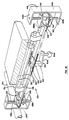
- a second embodiment of the mobility device is shown in the form of a stand-up walker 200 in Figure 22.
- the walker includes a frame 202 which supports a seat 204 pivotal between horizontal and vertical positions and a back rest 206.
- the support includes a releasable restraint bar 208 which assists in supporting the user as will be described.
- a wheel assembly similar to that in the aforementioned embodiment, and identified at 210 is located in the lower end of the frame for mobility while a pair of outriggers 212 extend transversely from the frame and adjacent to the wheels as will be described.
- the stand up walker 200 may also include a braking mechanism in accordance with braking mechanism 28 in the aforementioned embodiment and, in which case, is equipped with length adjustable arms 213.
- the frame structure is formed from left and right frame sections 214, 216, each of an "S"-shaped configuration, to form lower, middle and upper horizontal frame segments 214a, 214b, 214c and 216a, 216b, 216c respectively.
- the lower frame segments combine with a spanning member 218 which extends between the rear region of the lower segments 214a, 216a to form a base, while the upper segments 214c, 216c combine to form the left and right arms of the walker 200.
- Joining each of the lower and middle segments is a first vertical spanner 214d, 216d formed from a pair of telescoping elements which, joined by a bolt configuration identified at 220, so as to provide a walker 200 which may be disassembled.
- Disassembly is also provided by a second vertical spanner 214e, 216e formed from a pair of telescoping elements which, joined by a bolt configuration shown at 221 may be either disassembled or length adjusted.
- the restraint bar 208 is pivotally connected to the left arm 214c, while the opposite end of the restraint bar is coupled to the right arm 216c, by way of a releasable latch 222.
- each end of the lower frame segments Projecting longitudinally from each end of the lower frame segments are collars 224 which engage with the right angled ends 212a of rectangular outriggers 212. Joining the right angled ends thereof is a body member 212b.
- the collars 224 are further provided with a bore 224a which receives a pin to fix the outrigger 212 with the lower surface of the body member having an incremental spacing from the floor surface, for example one half inch.
- the outrigger 212 provides a support against inadvertent tipping of the walker 200.
- the seat 204 is pivotally connected to a pair of brackets 226 immediately below the back rest 206, which in turn is mounted on a fixed cross panel 228.
- the seat 204 provides a support for the patient in a partial sitting position in which, while gripping the arms 214c, 216 or the restraint bar 208 may propel the walker 200.
- the seat may be stored in a vertical position enabling the patient to walk with the support of the walker in a standing position, with further support being provided by a harness 230.
- the harness 230 includes a belt 232 which extends around the central region of the user, and has a releasable buckle in the rear portion thereof.
- the belt 232 is joined to the arms 214c, 216c by way of four expandable belts 234, which are coupled to the arms 214c, 216c by way of releasable brackets 236.
- FIG. 23 An alternative to the fixed outrigger is shown in Figure 23, wherein the pins are omitted from the collars so as to enable the outrigger 212 to rotate therein.
- a first link 240 is pivotally connected between a remote point on the front right angled member shown at 242 and a pivot point in the central region of a second link 244.
- the second link in turn is pivotally coupled to the vertical spanner 214d and has at its remote end, a handle 244a enabling the patient to rotate the second link upwardly in the direction of the arrow identified at "G". In this manner, the outrigger is easily retracted to a stored position, enabling the walker to pass through a doorway.
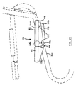
- a further alternative to the fixed outrigger is an automatically extendable outrigger 250 as shown in Figures 24 and 25.
- the automatic outrigger 250 is formed from a first housing 252 and a second housing 254, the second housing 254 being pivotal relative to the first housing 252, which is secured to the lower frame segment 214a.
- Located on the first housing 252 is an activation rod 256 which is oriented at one end 256a in close proximity with the floor surface, and is slidably engaged within brackets 258 extending near each end thereof from the first housing 252.
- the other end 256b of the activation rod 256 is engaged with a first latch 258 which is pivotally mounted to the first housing 252 and engages a catch 260 formed on the second housing.
- the second housing 254 is tubular and has one end 254a through which outwardly extends a deploy rod 262, which is slidably engaged with the inner surface of the second housing.
- the deploy rod is also biased to an outwardly extended position by way of a spring 263, also within the second housing and engaged with a boss 262a formed in the central region of the deploy rod 262.
- the other end 254b of the second housing has an aperture formed therein, through which the other end of the deploy rod 262b outwardly extends in a stored position as shown in Figure 24.
- the end of the deploy rod is defined by a circumferential groove 262c which engages with the finger 264a of a second latch 264, pivotally mounted to the second housing 254 and biased against the groove by a spring 266.
- the second latch 264 is activated by way of an abutment rod 268 which is positioned in a bracket 270 formed on the first housing 252 and adjusted to the required extension therefrom by way of a set screw 272, so as to engage the other end of the second latch 264 upon rotation of the second housing 254 with respect to the first housing 252 under the biasing force of a coil spring 276 joined therebetween.
- the angle through which the second housing 254 rotates and the relative length of the second housing 254 and the deploy rod 262 are choosen such that in the extended position, the frictional force between the inner wall of the second housing 254 and the second deploy rod 262 provides a binding reaction force, thereby enabling the housing and the deploy rod to function as a unitary support member against the force exerted by the patient against the frame 12 of the walker.
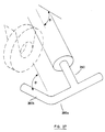
- the deploy rod 278 is formed with a "T"-shaped outward end, providing additional stability while at the same time distributing the force exerted on the deploy rod in its extended position.
- a deploy rod 280 has a "T"-shaped end, with one of the transversely extending arms 280a having a arm 280b extending inwardly at right angles to the transverse arm 280a.
- the inwardly extending arm is oriented at an angle ⁇ with respect to the axis of deploy rod 280, angle ⁇ corresponding to the angle in which the deploy rod 280 is located relative to the horizontal in the outwardly extended position. In this manner the deploy rod 280 provides further support to the outrigger in its extended position located adjacent the front or rear wheel.
- any number of outriggers may be located on the side of the walker.
- a convenient combination involves the placement of an outrigger adjacent each wheel.
- the harness 230 including six or more belts 234 to provide further support to the user.
- the use of different types of belts 230 such that the front belts have a different spring rate constant than the rear belts, thereby providing easier flexibility of the harness in one direction than in the other.
- the use of a higher spring constant in the rear pair of belts enables the user to flex the harness in the rearward direction while preventing the user from flexing the harness in the forward direction, thereby supporting the user against falling forward.
- FIG. 28 to 35 A further embodiment is illustrated in Figures 28 to 35 in the form of a chair 300.
- the chair has a frame 312 on which is positioned a seat 314 and a back 316, with the frame being supported by a wheel assembly 318.
- the wheel assembly 318 is of the same nature as those in the previous embodiments and will hereinafter not be discussed.
- the frame 312 includes arm portions 320a, 320b which are respectively connected to base portions 322a, 322b at an interconnection 324.
- the interconnection is provided by a swaged end formed on each of the arm portions and inserted into the end of the respective base portion.
- a screw element 325 establishes the tight engagement between the respective arm portion and base portion.
- a tray, identified at 328, joins the upper ends of the arm portions 320a, 320b.
- each of the base portions includes an inclined segment 322c and a horizontal segment 322d, with the horizontal segments being joined by a transverse segment 322e.
- the inclined horizontal and transverse segments are joined in continuous fashion and formed by a single tubular element which is bent to form the respective sections.
- a hole 323 In the bent region between the inclined and horizontal segments 322c and 322d respectively is a hole 323 to which is attached a foot rest of the type illustrated in previous embodiments.
- One of a pair of supports 322f joins the respective inclined segment with the adjacent horizontal segment. Pivotally mounted to the support 322f is a back support portion 326 formed of angular segments 326a, 326b which depend from a transverse segment 326c.
- a hole 326d is formed at the remote end of each of the respective angular segments to locate a tightening screw 328 which is threadably engaged with the respective support 322f.
- the horizontal segment 322d is also provided with a support post 330 which carries brackets 332 to locate the back support relative to the frame.
- Each of the brackets 332 includes spaced flanges 332a with a tightening screw 334 threadably engaged with one of the spaced flanges to engage the side wall of a respective angular member.
- the support post 330 is height adjustable by way of a rod portion 330a in threaded engagement with a cylindrical portion 330b.
- the back 316 includes a body 316a formed from a pair of side walls 316b joined to a transverse wall 316c.
- a cushion 316d is coupled to the transverse wall 316c by attaching a pair of complementary Velcro straps 316e located on the rear and front faces respectively of the cushion 316d in the transverse wall 316c.
- the seat 314 is positioned relative to the frame 322 by way of a transverse bar 318 which extends between the supports 322f.
- the seat 314 includes a base 314a having vertical side walls 314b upwardly extending from the lateral edges of a bottom panel 314c, a front portion of which is upwardly inclined in advance of the side walls 314b.
- a pair of brackets 314d engage the lower face of the transverse bar and are attached to the bottom panel 314c.
- a cushion 314e is of a shape complementary to the base 314a, and is connected thereto by way of complementary Velcro straps 314f positioned on the respective surfaces.
- the tray 328 is formed from an outer peripheral frame member 336, the respective ends of which abut the ends of the arm portions 320a, 320b, and an inner peripheral frame member 338 which is padded to offer protection against user injury.
- a panel 339 extends between the inner and outer frame members to provide a working surface.
- the tray has a first lateral end, identified at 340 in Figure 32, which locates an insert 342 adjacent a longitudinal slot 344. The slot receives a tightening screw 346 which is threadably engaged with a hole 342a in the insert 342.
- the tray is also provided with a second lateral end 348, shown in Figure 33 in which is welded an insert 350.
- a hole is provided in the lower face of the adjacent arm portion 320a and is identified at 352.
- a support strap 354 Surrounding the hole is a support strap 354 which is threaded with the hole to receive a tightening screw 356 for abutment in an annular groove 358 formed near the remote end of the insert 350. Also formed on the end of the adjacent arm portion 320a is an abutment 360 formed from a bent wire which is welded to the lower face of the arm portion. It is also to be noted that the arm portion 320b is provided with a hole and the appropriate support strap identified at 354a in Figure 32 in order to receive the insert 350 in an alternative configuration as will be described.
- the chair 300 is provided with a dampening mechanism 360 which is of the same form as that utilized in a previous embodiment, and will therefore not be discussed in detail further.
- the chair offers a number of advantages for the user, including a back rest 316 which is easily adjustable relative to the seat 314. This is achieved by simply adjusting the height of the support post 330 to cause the back rest 316 to rotate about supports 322f in the desired manner.
- the back rest also may be easily folded to a horizontal position to reduce the volume needed for shipping, simply by releasing the tightening screw 334 and rotating the back support frame about the supports 322f.
- movement of the seat 314 is dampened by the dampening mechanism.
- rotational limits of the chair may also be provided by way of a rotation limit device, and a spring may be used to bias the seat to a desired orientation.
- the tray also provides an enhanced versatility in that it may be pivoted from the operative position as shown in the drawings to a vertical orientation, depending from arm portion 320a simply by displacing the insert 342 in a forward direction. This is done by releasing tightening screw 346 and displacing the same forward along the slot 344 until the end of the insert 342 is removed from the arm portion 320b. The tray may then be pivoted about the insert 350, by releasing slightly the tightening screw 356. The rotation of the tray beyond the vertical depending orientation is inhibited by the abutment 360.
- the tray 328 has the additional feature in that it may be reversed to permit the tray to be pivoted to a vertical depending position from the arm portion 320b.
- the tightening screw 356 is released from the hole 352 and placed in the appropriately threaded hole and strap 354a as earlier noted.
- the tray is first brought forward to withdraw the inserts 342 and 350 from the respective arm portions, then reversed to enable the inserts 342, 350 to be placed in the opposite arm portions, thereby aligning the annular groove 358 with the repositioned tightening screw 356.
- the seat 314 may be split along a centre line parallel to the central axis of the frame portions, as is shown by dashed lines 354.
- a dampening mechanism 360 would be provided for each of the seat portions formed by such a separation. This would enable independent rotation of the seat segments which is considered particularly important in the case of stroke patients, as well as to geriatric patients, by providing exercise to the upper legs about the hips.
- the support post 330 may be height adjustable to a number of preset heights, thereby allowing the back support portion 326 to be oriented in a corresponding number of preset orientations relative to the chair.
- the chair has a frame assembly 412 including a rear section 414 to support a seat 416, a back 418 and a user support assembly 419, which is also coupled to the seat to allow coordinated movement therebetween as will be described.
- the frame assembly 412 has a pair of right and left hand front sections 420a, 420b which are removably attached to the right and left hand sides respectively of the rear section 414 by a pair of attachment assemblies 422a, 422b.
- the frame assembly 412 also supports the wheel assembly 423 and a foot rest assembly 424, as will be further described.
- the rear section 414 has right hand and left hand segments 426a, 426b respectively which are formed from a continuous tubular member.
- Each of the right hand and left hand segments has an upper portion 428 which is inclined slightly downwardly toward a lower horizontal portion 430, while a central portion 432 joins their respective front ends and is inclined slightly rearwardly from the vertical.
- a back support portion 434 depends from the rear end of the upper portion 428 and has a forwardly cantilevered seat support portion 436.
- An upper transverse member 438 joins the front ends of the seat support portions 436 while a lower transverse member joins the rear ends of the lower portions 430.
- Each of the right and left hand front sections 420a, 420b includes upper and lower portions 444, 446 which are parallel to the respective inclined and horizontal portions of the rear section, and are joined at their front and rear ends respectively by front and rear portions 448, 450 which are oriented parallel relative to the central portion 432.
- attachment assemblies 422a, 422b are shown in more detail in Figure 41 and include a pair of pins 452 extending from the rear face of the rear portions 450 to be inserted into corresponding holes 432a formed in the front face of the central portions 432.
- a ball clamp 454 encompasses the laterally inner and outer peripheries of the central and rear portions and is formed by a pair of clamp segments 454a, 454b. Each of the segments has an inner surface 454c complementary with the outer surface of the respective frame portion, while holes are provided at 454d to receive a tightening screw 454e.
- a rear caster wheel 456 and a middle fixed wheel 458 are provided on the lower portion 430, while a front caster wheel 460 is positioned at the front of the lower portion 446.
- the wheel assembly 423 operates in the same manner as in previous embodiments and will thus not be described further.
- Each of the lower portions 430 also supports a pair of foot rest assemblies 423, which include a foot rest member 423a pivotally mounted on a shaft member 423b, the ends of which are bent so as to be attached to the corresponding inner side face of the lower portion 430.
- a particular feature of the chair 410 is the user support assembly 419 which is illustrated in more detail in Figure 39.
- a support member 462 is pivotally mounted to the upper ball clamp element 454a and to a belt 464, by way of pivot mechanisms 466 and 468.
- the belt 464 is formed from a pair of rigid curved panels 470 with a foam liner 472 attached to each of their inner faces, and a stretchable pad 473 extending between their rear remote ends.
- a pair of straps 476a, 476b extend from the front remote ends of the curved panels 470, with the strap 476b terminating at a buckle 478.
- the user support assembly 419 is adaptable to a number of waist sizes.
- the user support assembly 419 is height adjustable for a wide range of user waist heights.
- FIG. 40 illustrating the pivot mechanism 466 which is attached to the respective curved panel 470 by way of a hole 470a and a corresponding screw 470b extending through the hole to engage a bronze bearing shoulder 470c.
- a bearing surface 470d extends outwardly from the bearing shoulder 470c on which is placed a nylon washer 470e, pivot elements 470f, 470g, a washer 470h and a threaded cap 470i, the threaded cap being threaded to the remote end of the surface 470d.
- the pivot element 470f is fixed to the upper end of the support member 462 while the pivot element 470g is attached to a lever as will be discussed.
- the pivot mechanism 468 is equivalent in structure to the pivot mechanism 466 with the exception that the shoulder 470c is mounted to the inside ball clamp member 454a. In addition, a pivot element corresponding to 470f is not used in pivot mechanism 468. With reference to Figure 42, there is also provided a block 472 affixed to the inner surface of the rear frame portion 450 for limiting forward movement of the support member 462.
- the user enters the chair from the front between the frame sections.
- the support assembly 419 is then strapped around the user's waist, with the appropriate adjustments made for height and width by way of the upper ball clamps 454 and the buckle 478 accordingly.
- the user may then operate the chair in a standing position, wherein the lever member 474 ensures that the seat 414 is in a storage position so as not to interfere with the movement of the user.
- the user is then free to manoeuvre the chair in the desired direction so as to exercise his legs, while grasping the upper frame portions for support.
- the blocks 472 prevent the rotation of the support member 462, thereby preventing his falling forward in the chair.
- the levers 474 are displaced downwardly to cause corresponding rotation of the seat 414 to the operative position.
- the support member 462 ensures the safe alignment of the users buttocks with the seat 414.
- left and right hand front sections 420a, 420b not only reduces the space requirements for shipping, but also allows the chair to be used in one of two configurations.
- the right and left front sections 420a, 420b provide a support rail extending in front of the chair 410, by way of upper portions 444. Being inclined, the support rail allows the user to support himself in a comfortable stance at a range of locations depending on his height, arm length and the like, while at the same time provides additional support for the user when entering the chair 410.
- a further feature of the chair 410 is the inherent flexibility afforded by the rectangular spiral shape of the frame sections 426a, 426b, which serves to absorb vibrations in the rolling surface, while reducing the force of impact should the user fall.
Landscapes
- Health & Medical Sciences (AREA)
- Animal Behavior & Ethology (AREA)
- Veterinary Medicine (AREA)
- Public Health (AREA)
- General Health & Medical Sciences (AREA)
- Life Sciences & Earth Sciences (AREA)
- Rehabilitation Therapy (AREA)
- Physical Education & Sports Medicine (AREA)
- Pain & Pain Management (AREA)
- Epidemiology (AREA)
- Rehabilitation Tools (AREA)
- Vehicle Body Suspensions (AREA)
- Vending Machines For Individual Products (AREA)
- Liquid Crystal Substances (AREA)
- Handcart (AREA)
- Seal Device For Vehicle (AREA)
Claims (38)
- Fahrbare Stützvorrichtung (10) für behinderte Personen, zum Abrollen auf einer Reaktionsfläche, mit einer ersten und einer zweiten, sich in Längsrichtung erstreckenden Rahmensektion (34, 36), die in gegenseitigem Abstand zueinander ausgerichtet sind; mit einem Rückentragteil (12), das sich quer zwischen der ersten und der zweiten Rahmensektion (34, 36) erstreckt und an diese angekoppelt ist; mit einem Sitzteil (14), das sich quer zwischen der ersten und der zweiten Rahmensektion (34, 36) erstreckt und an diese angekoppelt ist; wobei die beiden Rahmensektionen einen unteren Teil (34a, 36a) aufweisen; mit einer Radeinheit (24), die an den unteren Teilen (34a, 36a) anmontiert ist, um die Reaktionsfläche zu erfassen, wobei die Radeinheit (24) ein Paar vordere Schwenkräder (48) und ein Paar hintere Schwenkräder (50) aufweist, dadurch gekennzeichnet, daß die Radeinheit (24) ein Paar Zwischenräder (53) aufweist, deren jedes eine feste, querverlaufende Drehachse hat und zwischen den vorderen und den hinteren Schwenkrädern (48, 50) angeordnet ist, um eine Querbewegung zu verhindern, wobei jedes der genannten Räder (48, 50, 53) eine unterste Tangente aufweist, die in einer gemeinsamen Ebene liegt, daß die genannten unteren Teile steif sind, um eine relative vertikale Verschiebung zwischen den Schwenkrädern (48, 50) und den Zwischenrädern (53) zu verhindern, um ein Schaukeln der Rahmensektionen (34, 36) um die Zwischenräder (53) zu verhindern, daß jede Rahmensektion einen Frontteil (34b, 36b) aufweist, daß die Frontteile (34b, 36b) einen gegenseitigen Abstand haben, so daß die behinderte Person uneingeschränkten Zugang zum Sitzteil (14), zum Rückentragteil (16) und zu einem freien Bereich vor dem Sitzteil (14) aufweist, durch welchen die Füße der Person die Reaktionsfläche erreichen und eine Antriebskraft auf die Vorrichtung (10) ausüben können.
- Fahrbare Stützvorrichtung (10) nach Anspruch 1, dadurch gekennzeichnet, daß die vorderen Schwenkräder (48), die hinteren Schwenkräder (50) und die Zwischenräder (53) an jeder Rahmensektion im wesentlichen parallel zu einer zentralen Längsachse der fahrbaren Stützvorrichtung ausgerichtet sind.
- Fahrbare Stützvorrichtung (10) nach Anspruch 1, weiterhin umfassend ein lösbares Haltemittel (32), das im Bereich des Sitzteiles (14) angeordnet und an die erste und die zweite Rahmensektion (34, 36) angekoppelt ist.
- Fahrbare Stützvorrichtung (10) nach Anspruch 3, wobei das Sitzteil (14) relativ zur ersten und zur zweiten Rahmensektion (34, 36) schwenkbar ist.
- Fahrbare Stützvorrichtung (10) nach Anspruch 4, wobei das Sitzteil (14) schwenkbar ist zwischen einer ersten Position und einer zweiten Position, in welcher sich das Sitzteil (14) in einer nach vorn geneigten Position befindet.
- Fahrbare Stützvorrichtung (10) nach Anspruch 5, wobei die erste Position eine nach hinten und unten geneigte Position ist.
- Fahrbare Stützvorrichtung (10) nach Anspruch 1, weiterhin umfassend Justiermittel (94) zum Justieren der Höhe des Sitzteiles (14) relativ zu den Rahmensektionen (34, 36).
- Fahrbare Stützvorrichtung (10) nach Anspruch 7, wobei das Sitzteil (14) einen Sitzrahmen (90) aufweist, der relativ zu den Rahmensektionen (34, 36) beweglich ist, wobei die Justiermittel (94) ein Führungsmittel (80a) umfassen, das mit dem Sitzrahmen (90) zusammenarbeitet, um den Sitzrahmen (90) entlang eines vorgegebenen Weges relativ zu den Rahmensektionen (34, 36) zu führen.
- Fahrbare Stützvorrichtung (10) nach Anspruch 8, wobei der Sitzrahmen (90) ein Schwenkelement (78) aufweist, das eine Drehachse des Sitzteiles (14) definiert und relativ zum Führungsmittel (80a) beweglich ist.
- Fahrbare Stützvorrichtung (10) nach Anspruch 9, wobei das Justiermittel eine Zahnstangen-Ritzel-Anordnung (82, 84) umfaßt, um das Schwenkelement (78) relativ zum Führungsmittel (80a) zu verschieben.
- Fahrbare Stützvorrichtung (10) nach Anspruch 10, wobei die Zahnstangen-Ritzel-Anordnung (82, 84) ein Zahnstangenelement (82) aufweist, das am Schwenkelement (78) fixiert ist, und ein Ritzelelement (84), das mit dem Führungsmittel (80a) drehbar gekoppelt ist, um das Zahnstangenelement (82) relativ hierzu zu verschieben.
- Fahrbare Stützvorrichtung (10) nach Anspruch 3, wobei der obere Bereich der ersten und zweiten Rahmensektionen (34, 36) Armelemente (18, 20) auf beiden Seiten des Sitzteiles (14) bilden.
- Fahrbare Stützvorrichtung (10) nach Anspruch 12, wobei eines der Armelemente (18, 20) von der betreffenden Rahmensektion (34, 36) abnehmbar ist.
- Fahrbare Stützvorrichtung (10) nach Anspruch 12, wobei eines der Armelemente (18, 20) relativ zur betreffenden Rahmensektion schwenkbar ist.
- Fahrbare Stützvorrichtung (10) nach Anspruch 12, wobei das Haltemittel ein Tablett (22) aufweist, das an einem der Armelemente (18, 20) lösbar angeschlossen ist.
- Fahrbare Stützvorrichtung (10) nach Anspruch 15, wobei das Tablett (22) eine solche Kontur hat, daß es einen Handgriff bildet.
- Fahrbare Stützvorrichtung (10) nach Anspruch 15, wobei sich das Tablett (162) entlang eines der Armelemente (18, 20) erstreckt, um eine Armstütze zu bilden.
- Fahrbares Stützelement (10) nach Anspruch 1, weiterhin umfassend eine Bremse (26) zum Schaffen eines lösbaren Widerstandes gegen die Umdrehung der Räder (48, 50, 53).
- Fahrbare Stützvorrichtung (10) nach Anspruch 18, wobei die Bremse (26) derart angeordnet ist, daß sie die Zwischenräder (53) abbremst, wobei die Bremse (26) ein Paar Bremsklötze (29) aufweist, deren jeder mit einem entsprechenden Zwischenrad (53) in Eingriff bringbar ist, sowie ein Betätigungsmittel (26), um den Bremsklotz (29) mit den Zwischenrädern (53) in Eingriff zu bringen.
- Fahrbare Stützvorrichtung (10) nach Anspruch 19, wobei das Betätigungsmittel (26) weiterhin ein Paar Hebel (26) aufweist, deren jeder schwenkbar an eine entsprechende Rahmensektion angekoppelt ist.
- Fahrbare Stützvorrichtung (10) nach Anspruch 20, wobei die Hebel (26) an einer gemeinsamen Schwenkstange (58) entlang der Schwenkachse befestigt sind.
- Fahrbare Stützvorrichtung (10) nach Anspruch 1, weiterhin umfassend eine Fußstütze (125), die sich vor den Rahmensektionen (34, 36) erstreckt und an eines der Rahmensektionen angekoppelt ist.
- Fahrbare Stützvorrichtung (10) nach Anspruch 22, wobei die Fußstütze (125) ein ausfahrbares Element (126, 128) aufweist, ferner einen Justiermechanismus (129) zum Justieren der Länge des ausfahrbaren Elementes (126, 128).
- Fahrbare Stützvorrichtung nach Anspruch 1, wobei das Sitzteil (164) ein erstes Teil (174) aufweist, das gelenkig an einem zweiten Teil (166) angeschlossen ist.
- Fahrbare Stützvorrichtung (410) nach Anspruch 1, wobei jede Rahmensektion einen vorderen Rahmenteil (420) und einen hinteren Rahmenteil (414) aufweist, wobei das Zentralrad (458) und das hintere Schwenkrad (456) am hinteren Rahmenteil (414), und das vordere Schwenkrad (460) am vorderen Rahmenteil (420) angeschlossen sind.
- Fahrbare Stützvorrichtung (200) für behinderte Personen, abrollbar auf einer Reaktionsfläche, von jener Bauart, die eine erste und eine zweite, in Längsrichtung sich erstreckende Rahmensektion umfaßt, die im gegenseitigen Abstand zueinander ausgerichtet sind; mit einem Rückenstützteil (206), der sich zwischen den Rahmensektionen (214, 216) quer erstreckt und an diese angekoppelt ist; mit einem Sitzteil (204), das sich zwischen den Rahmensektionen (214, 216) quer erstreckt und an diese angekoppelt ist; wobei die beiden Rahmensektionen jeweils einen unteren Teil (214a, 216a) aufweisen; mit einer Radeinheit (210), die an den unteren Teilen (214a, 216a) anmontiert ist, um die Reaktionsfläche zu erfassen, wobei die Radeinheit (210) ein Paar vordere Schwenkräder (48) und ein Paar hintere Schwenkräder (5) umfaßt,
dadurch gekennzeichnet, daß die Radeinheit (210) ein Paar Zentralräder (53) aufweist, die jeweils eine feste, in Querrichtung verlaufende Drehachse aufweisen und zwischen den vorderen und den hinteren Schwenkrädern angeordnet sind, um eine Querbewegung zu verhindern, daß jedes Rad (48, 50, 53) eine untere Tangente aufweist, die in einer gemeinsamen Ebene liegt, daß die genannten unteren Teile steif sind, um eine relative Vertikalbewegung zwischen den Schwenkrädern (48, 50) und den Zentralrädern (53) zu vermeiden, um ein Schaukeln der Rahmensektionen (214, 216) um die Zentralräder (53) zu vermeiden, daß jede Rahmensektion einen vorderen Bereich (214b, 216b) aufweist, die jeweils einen gegenseitigen Abstand aufweisen, so daß die behinderte Person zum Sitzteil (204), zum Rückenstützteil (16) und zu einem freien Bereich vor dem Sitzteil (204) ungehinderten Zugang hat, durch welche die Füße der Person die Reaktionsfläche erreichen und eine Antriebskraft auf die Vorrichtung (200) ausüben können, daß die Rahmensektionen (214, 216) einen oberen Teil (214c, 216c) aufweisen, die mit den genannten unteren Teilen (214a, 216a) im wesentlichen parallel verlaufen horizontal und im Abstand angeordnet ist, und einen zentralen Teil (214b, 216b), das an ein Ende des oberen Teiles angeschlossen ist, mit einem gegenüberliegenden Ende des unteren Teiles. - Fahrbare Tragvorrichtung (200) nach Anspruch 26, wobei der zentrale Teil (214b, 216b) aus dem ersten und dem zweiten Rahmenelement gebildet ist, wobei das erste Rahmenelement an das hintere Ende des oberen Teiles, und das zweite Rahmenelement an das vordere Ende des unteren Teiles angeschlossen ist, und wobei die zentralen Rahmenelemente an ihren Enden teleskopierbar miteinander verbindbar sind.
- Fahrbare Tragvorrichtung (200) nach Anspruch 27, weiterhin umfassend ein Auskragmittel (212), das an den unteren Teilen lösbar befestigt ist, um sich hiervon nach außen zu erstrecken und die Reaktionsfläche zu erfassen, um die Stabilität der Vorrichtung zu erhöhen.
- Fahrbare Tragvorrichtung (200) nach Anspruch 28, wobei das Auskragmittel (212) aus einer zurückgezogenen Position in eine ausfahrbare Position lösbar ist.
- Fahrbare Tragvorrichtung (200) nach Anspruch 29, weiterhin umfassend Auslösemittel (256), um das Auskragmittel (254, 262) aus der zurückgezogenen Position in die ausgefahrene Position freizugeben.
- Fahrbare Tragvorrichtung (200) nach Anspruch 30, wobei das Auslösemittel (256) auf eine Verdrehung der Vorrichtung um die genannte zentrale Längsachse anspricht.
- Fahrbare Tragvorrichtung (200) nach Anspruch 31, wobei das Auskragmittel (254, 262) schwenkbar an den unteren Teilen montiert ist und weiterhin einen Stab (262) aufweist, der in einem ersten Gehäuse (252) gleitet und sich von hier aus beim Freigeben des Auskragmittels (254, 262) erstreckt.
- Fahrbare Tragvorrichtung (200) nach Anspruch 32, wobei das erste Gehäuse (252) gegen die ausgefahrene Position geneigt ist.
- Fahrbare Tragvorrichtung (200) nach Anspruch 33, wobei das Auslösemittel (256) einen ersten Riegel (258, 260) aufweist, der durch ein Riegelelement (262) lösbar ist, angeordnet dicht bei der Reaktionsfläche, um die Reaktionsfläche bei einem Verdrehen der Vorrichtung um die vorbestimmte horizontale Achse zu erfassen.
- Fahrbare Tragvorrichtung (200) nach Anspruch 34, wobei das Auslösemittel (256) ein zweites Verriegelungsmittel (264) umfaßt, um den Stab (262) bei Freigabe des Auskragmittels (254, 262) freizugeben.
- Fahrbare Tragvorrichtung (200) nach Anspruch 35, wobei das erste Verriegelungsmittel (258, 260) an einem zweiten Gehäuse (254) angelenkt ist, während das zweite Verriegelungsmittel (264) am ersten Gehäuse (252) angelenkt ist.
- Fahrbare Tragvorrichtung (200) nach Anspruch 36, wobei das erste Gehäuse (252) im Bezug auf das zweite Gehäuse (254) schwenkbar gelagert ist und das zweite Gehäuse (254) einen Anschlag bildet, um das zweite Verriegelungsmittel (264) bei Ankunft des ersten Gehäuses (252) in der ausgefahrenen Position zu erfassen, um den Stab (262) freizugeben.
- Fahrbare Tragvorrichtung nach Anspruch 1, wobei jedes vordere Schwenkrad (48), jedes hintere Schwenkrad (50) und die genannten Zwischenräder (53) an dem entsprechenden unteren Teil (34a, 36a) fest montiert sind, um eine relative vertikale Verschiebung zwischen den Rädern und dem unteren Teil zu verhindern.
Priority Applications (1)
| Application Number | Priority Date | Filing Date | Title |
|---|---|---|---|
| AT87904548T ATE86468T1 (de) | 1986-07-18 | 1987-07-17 | Mobile tragevorrichtung. |
Applications Claiming Priority (4)
| Application Number | Priority Date | Filing Date | Title |
|---|---|---|---|
| CA514111 | 1986-07-18 | ||
| CA000514111A CA1265733A (en) | 1986-07-18 | 1986-07-18 | Mobility support device |
| US46828 | 1987-05-06 | ||
| US07/046,828 US4893826A (en) | 1987-05-06 | 1987-05-06 | Mobility support device |
Publications (2)
| Publication Number | Publication Date |
|---|---|
| EP0317559A1 EP0317559A1 (de) | 1989-05-31 |
| EP0317559B1 true EP0317559B1 (de) | 1993-03-10 |
Family
ID=25671051
Family Applications (1)
| Application Number | Title | Priority Date | Filing Date |
|---|---|---|---|
| EP87904548A Expired - Lifetime EP0317559B1 (de) | 1986-07-18 | 1987-07-17 | Mobile tragevorrichtung |
Country Status (7)
| Country | Link |
|---|---|
| EP (1) | EP0317559B1 (de) |
| JP (1) | JPH01503201A (de) |
| AT (1) | ATE86468T1 (de) |
| AU (1) | AU7694087A (de) |
| CA (1) | CA1265733A (de) |
| DE (2) | DE317559T1 (de) |
| WO (1) | WO1988000460A1 (de) |
Families Citing this family (8)
| Publication number | Priority date | Publication date | Assignee | Title |
|---|---|---|---|---|
| US5333929A (en) * | 1992-06-02 | 1994-08-02 | Slagerman Engineering Ltd. | Wheelchair tray |
| JP2568974B2 (ja) * | 1993-06-30 | 1997-01-08 | 平 岡本 | 車椅子の肘掛け |
| WO1996036306A1 (en) * | 1995-05-17 | 1996-11-21 | Scicare Systems International, Incorporated | Multi-purpose activity and exercise system |
| AU4709996A (en) * | 1996-03-01 | 1997-09-16 | Pacific 21 Pty Ltd | Side frame for a wheelchair and a wheelchair incorporating same |
| US6974142B1 (en) | 1999-11-13 | 2005-12-13 | Nippon Clean Engine Research Institute Co., Ltd. | Vehicle to assist walking |
| JP5626827B2 (ja) * | 2009-09-01 | 2014-11-19 | 公立大学法人高知工科大学 | 歩行訓練機 |
| JP6327664B2 (ja) * | 2013-12-25 | 2018-05-23 | 奨悟 北村 | 椅子 |
| CN110578658B (zh) * | 2019-10-11 | 2023-12-01 | 江苏越科新材料有限公司 | 一种风电叶片模具专用转运支撑装置及其使用方法 |
Family Cites Families (16)
| Publication number | Priority date | Publication date | Assignee | Title |
|---|---|---|---|---|
| GB592282A (en) * | 1945-04-20 | 1947-09-12 | Sam Duke | Improvements in invalid walkers |
| US1611807A (en) * | 1926-01-05 | 1926-12-21 | Bergh Martha | Exercising device |
| US1638426A (en) * | 1926-02-15 | 1927-08-09 | Brown George | Baby walker |
| US2165700A (en) * | 1935-07-25 | 1939-07-11 | Glynn Henry | Invalid walking support |
| US2578382A (en) * | 1947-07-25 | 1951-12-11 | Thompson Joseph Henry | Equipment for use in handling invalids |
| US2630160A (en) * | 1950-09-19 | 1953-03-03 | George E Friedman | Adjustable mobile chair for spastic children |
| GB832913A (en) * | 1955-10-18 | 1960-04-21 | Vida Elizabeth Kirkpatrick | Improvements in or relating to walking-aid apparatus |
| GB1251779A (de) * | 1969-09-02 | 1971-10-27 | ||
| US3788695A (en) * | 1971-07-12 | 1974-01-29 | N Salem | Sitting/standing table/walker combination |
| US3883175A (en) * | 1973-08-23 | 1975-05-13 | Everest & Jennings | Swing-back detachable wheelchair armrest |
| JPS54162892A (en) * | 1978-06-15 | 1979-12-24 | Shiyouji Hirano | Chair |
| GB2047528A (en) * | 1979-04-03 | 1980-12-03 | Vessa Ltd | Wheelchair having a detachable armrest |
| JPS5842127B2 (ja) * | 1980-01-28 | 1983-09-17 | 日本鉱業株式会社 | 弗素含有泥から硅弗化水素酸を回収する方法 |
| US4384713A (en) * | 1980-05-28 | 1983-05-24 | White Cap Enterprises Corporation | Safety rolling invalid walker |
| US4433869A (en) * | 1980-12-15 | 1984-02-28 | Dawn Designs, Inc. | Baby walker |
| JPS58165847A (ja) * | 1982-03-26 | 1983-09-30 | 社会福祉法人神奈川県総合リハビリテ−シヨン事業団 | 車いす |
-
1986
- 1986-07-18 CA CA000514111A patent/CA1265733A/en not_active Expired
-
1987
- 1987-07-17 WO PCT/GB1987/000507 patent/WO1988000460A1/en not_active Ceased
- 1987-07-17 DE DE198787904548T patent/DE317559T1/de active Pending
- 1987-07-17 EP EP87904548A patent/EP0317559B1/de not_active Expired - Lifetime
- 1987-07-17 AU AU76940/87A patent/AU7694087A/en not_active Abandoned
- 1987-07-17 DE DE87904548T patent/DE3784729T2/de not_active Expired - Lifetime
- 1987-07-17 JP JP62504253A patent/JPH01503201A/ja active Pending
- 1987-07-17 AT AT87904548T patent/ATE86468T1/de not_active IP Right Cessation
Also Published As
| Publication number | Publication date |
|---|---|
| WO1988000460A1 (en) | 1988-01-28 |
| EP0317559A1 (de) | 1989-05-31 |
| JPH01503201A (ja) | 1989-11-02 |
| CA1265733A (en) | 1990-02-13 |
| DE3784729D1 (de) | 1993-04-15 |
| AU7694087A (en) | 1988-02-10 |
| ATE86468T1 (de) | 1993-03-15 |
| DE317559T1 (de) | 1990-03-01 |
| DE3784729T2 (de) | 1993-10-14 |
Similar Documents
| Publication | Publication Date | Title |
|---|---|---|
| US5301968A (en) | Mobility support device | |
| US5697628A (en) | Wheelchair exercise and support bar apparatus and method | |
| US5603677A (en) | Weight assisted rehabilitation system | |
| US5058912A (en) | Combination chair/walker | |
| US5419571A (en) | Wheel chair with provisions for patient walker | |
| US4802542A (en) | Powered walker | |
| US5224717A (en) | Walking aid device | |
| US5275426A (en) | Thoracic suspension walker | |
| US6161860A (en) | Collapsible and convertible walker for disabled persons | |
| US5356172A (en) | Sliding seat assembly for a propelled wheel chair | |
| US4207879A (en) | Therapeutic apparatus for use in treatment of muscular and skeletal disorders | |
| US3388700A (en) | Means and process for effecting periodic body inversion | |
| US4608969A (en) | Portable traction apparatus | |
| US5340139A (en) | Ambulatory wheelstand with torso and leg support | |
| US4893826A (en) | Mobility support device | |
| JPH038775B2 (de) | ||
| US4744578A (en) | User inclinable prone stander type wheelchair | |
| US3848870A (en) | Exercise apparatus on pedestal for patients | |
| US4155126A (en) | Universal hospital chair | |
| US5005829A (en) | Exercise machine for patients confined to bed | |
| EP0456718A1 (de) | Kombination aus rollstuhl und gehhilfe | |
| JP4995400B2 (ja) | 車輪付歩行器 | |
| EP0278974A4 (de) | Kombination aus rollstuhl und gehhilfe. | |
| EP1510193A1 (de) | Rollstuhl ausgestattet mit Beinstütze und Wadenstütze | |
| US4927167A (en) | Ambulatory wheelstand |
Legal Events
| Date | Code | Title | Description |
|---|---|---|---|
| PUAI | Public reference made under article 153(3) epc to a published international application that has entered the european phase |
Free format text: ORIGINAL CODE: 0009012 |
|
| 17P | Request for examination filed |
Effective date: 19890118 |
|
| AK | Designated contracting states |
Kind code of ref document: A1 Designated state(s): AT BE CH DE FR GB IT LI LU NL SE |
|
| TCNL | Nl: translation of patent claims filed | ||
| EL | Fr: translation of claims filed | ||
| TCAT | At: translation of patent claims filed | ||
| ITCL | It: translation for ep claims filed |
Representative=s name: BARZANO' E ZANARDO MILANO S.P.A. |
|
| DET | De: translation of patent claims | ||
| 17Q | First examination report despatched |
Effective date: 19901204 |
|
| GRAA | (expected) grant |
Free format text: ORIGINAL CODE: 0009210 |
|
| AK | Designated contracting states |
Kind code of ref document: B1 Designated state(s): AT BE CH DE FR GB IT LI LU NL SE |
|
| PG25 | Lapsed in a contracting state [announced via postgrant information from national office to epo] |
Ref country code: SE Effective date: 19930310 Ref country code: NL Effective date: 19930310 Ref country code: LI Effective date: 19930310 Ref country code: CH Effective date: 19930310 Ref country code: BE Effective date: 19930310 Ref country code: AT Effective date: 19930310 |
|
| REF | Corresponds to: |
Ref document number: 86468 Country of ref document: AT Date of ref document: 19930315 Kind code of ref document: T |
|
| REF | Corresponds to: |
Ref document number: 3784729 Country of ref document: DE Date of ref document: 19930415 |
|
| RAP2 | Party data changed (patent owner data changed or rights of a patent transferred) |
Owner name: CANHART INDUSTRIES LIMITED |
|
| ITF | It: translation for a ep patent filed | ||
| REG | Reference to a national code |
Ref country code: CH Ref legal event code: PL |
|
| ET | Fr: translation filed | ||
| PG25 | Lapsed in a contracting state [announced via postgrant information from national office to epo] |
Ref country code: LU Free format text: LAPSE BECAUSE OF NON-PAYMENT OF DUE FEES Effective date: 19930731 |
|
| NLV1 | Nl: lapsed or annulled due to failure to fulfill the requirements of art. 29p and 29m of the patents act | ||
| PLBE | No opposition filed within time limit |
Free format text: ORIGINAL CODE: 0009261 |
|
| STAA | Information on the status of an ep patent application or granted ep patent |
Free format text: STATUS: NO OPPOSITION FILED WITHIN TIME LIMIT |
|
| 26N | No opposition filed | ||
| PGFP | Annual fee paid to national office [announced via postgrant information from national office to epo] |
Ref country code: FR Payment date: 19950717 Year of fee payment: 9 |
|
| PGFP | Annual fee paid to national office [announced via postgrant information from national office to epo] |
Ref country code: DE Payment date: 19950725 Year of fee payment: 9 |
|
| PGFP | Annual fee paid to national office [announced via postgrant information from national office to epo] |
Ref country code: GB Payment date: 19950727 Year of fee payment: 9 |
|
| PG25 | Lapsed in a contracting state [announced via postgrant information from national office to epo] |
Ref country code: GB Effective date: 19960717 |
|
| GBPC | Gb: european patent ceased through non-payment of renewal fee |
Effective date: 19960717 |
|
| PG25 | Lapsed in a contracting state [announced via postgrant information from national office to epo] |
Ref country code: FR Effective date: 19970328 |
|
| PG25 | Lapsed in a contracting state [announced via postgrant information from national office to epo] |
Ref country code: DE Effective date: 19970402 |
|
| REG | Reference to a national code |
Ref country code: FR Ref legal event code: ST |
|
| PG25 | Lapsed in a contracting state [announced via postgrant information from national office to epo] |
Ref country code: IT Free format text: LAPSE BECAUSE OF NON-PAYMENT OF DUE FEES Effective date: 20050717 |