EP0317681B1 - Verfahren und Vorrichtung zur kontinuierlichen Aufbereitung von Pflanzenstengeln - Google Patents
Verfahren und Vorrichtung zur kontinuierlichen Aufbereitung von Pflanzenstengeln Download PDFInfo
- Publication number
- EP0317681B1 EP0317681B1 EP87402990A EP87402990A EP0317681B1 EP 0317681 B1 EP0317681 B1 EP 0317681B1 EP 87402990 A EP87402990 A EP 87402990A EP 87402990 A EP87402990 A EP 87402990A EP 0317681 B1 EP0317681 B1 EP 0317681B1
- Authority
- EP
- European Patent Office
- Prior art keywords
- sheet
- stalks
- longitudinally
- rippling
- movement
- Prior art date
- Legal status (The legal status is an assumption and is not a legal conclusion. Google has not performed a legal analysis and makes no representation as to the accuracy of the status listed.)
- Expired - Lifetime
Links
- 238000000034 method Methods 0.000 title claims abstract description 37
- 238000002360 preparation method Methods 0.000 title claims abstract description 23
- 230000033001 locomotion Effects 0.000 claims abstract description 36
- 241000196324 Embryophyta Species 0.000 claims abstract description 24
- 241000208202 Linaceae Species 0.000 claims abstract description 18
- 235000004431 Linum usitatissimum Nutrition 0.000 claims abstract description 18
- 244000025254 Cannabis sativa Species 0.000 claims abstract description 7
- 235000012766 Cannabis sativa ssp. sativa var. sativa Nutrition 0.000 claims abstract description 7
- 235000012765 Cannabis sativa ssp. sativa var. spontanea Nutrition 0.000 claims abstract description 7
- 235000009120 camo Nutrition 0.000 claims abstract description 7
- 235000005607 chanvre indien Nutrition 0.000 claims abstract description 7
- 239000011487 hemp Substances 0.000 claims abstract description 7
- 238000011144 upstream manufacturing Methods 0.000 claims abstract 2
- 239000000835 fiber Substances 0.000 claims description 34
- 239000004753 textile Substances 0.000 claims description 16
- 238000000227 grinding Methods 0.000 claims description 13
- 238000004140 cleaning Methods 0.000 claims description 8
- 230000000737 periodic effect Effects 0.000 claims description 4
- 238000000151 deposition Methods 0.000 claims 2
- 238000003892 spreading Methods 0.000 claims 2
- 238000009434 installation Methods 0.000 abstract description 21
- 230000015572 biosynthetic process Effects 0.000 abstract description 5
- 238000009991 scouring Methods 0.000 description 10
- 239000010902 straw Substances 0.000 description 10
- 239000000463 material Substances 0.000 description 7
- 241000272522 Anas Species 0.000 description 6
- 238000000926 separation method Methods 0.000 description 5
- 238000004519 manufacturing process Methods 0.000 description 4
- 238000011282 treatment Methods 0.000 description 4
- 239000000428 dust Substances 0.000 description 3
- 244000144992 flock Species 0.000 description 3
- 239000002775 capsule Substances 0.000 description 2
- 238000010586 diagram Methods 0.000 description 2
- 238000006073 displacement reaction Methods 0.000 description 2
- 238000003306 harvesting Methods 0.000 description 2
- 238000009987 spinning Methods 0.000 description 2
- 239000002699 waste material Substances 0.000 description 2
- 241000288673 Chiroptera Species 0.000 description 1
- 244000060234 Gmelina philippensis Species 0.000 description 1
- 241001417494 Sciaenidae Species 0.000 description 1
- 241001249696 Senna alexandrina Species 0.000 description 1
- 229910000831 Steel Inorganic materials 0.000 description 1
- 230000001464 adherent effect Effects 0.000 description 1
- 238000013459 approach Methods 0.000 description 1
- 230000000712 assembly Effects 0.000 description 1
- 238000000429 assembly Methods 0.000 description 1
- 230000003416 augmentation Effects 0.000 description 1
- YFXPPSKYMBTNAV-UHFFFAOYSA-N bensultap Chemical compound C=1C=CC=CC=1S(=O)(=O)SCC(N(C)C)CSS(=O)(=O)C1=CC=CC=C1 YFXPPSKYMBTNAV-UHFFFAOYSA-N 0.000 description 1
- 230000004071 biological effect Effects 0.000 description 1
- 238000009960 carding Methods 0.000 description 1
- 239000000969 carrier Substances 0.000 description 1
- 230000003749 cleanliness Effects 0.000 description 1
- 239000011248 coating agent Substances 0.000 description 1
- 238000000576 coating method Methods 0.000 description 1
- 238000009833 condensation Methods 0.000 description 1
- 230000005494 condensation Effects 0.000 description 1
- 238000005336 cracking Methods 0.000 description 1
- 230000001627 detrimental effect Effects 0.000 description 1
- 238000011161 development Methods 0.000 description 1
- 230000018109 developmental process Effects 0.000 description 1
- 238000010410 dusting Methods 0.000 description 1
- 230000000694 effects Effects 0.000 description 1
- 235000021183 entrée Nutrition 0.000 description 1
- 238000000605 extraction Methods 0.000 description 1
- 239000002657 fibrous material Substances 0.000 description 1
- 230000005484 gravity Effects 0.000 description 1
- 238000000265 homogenisation Methods 0.000 description 1
- 239000012535 impurity Substances 0.000 description 1
- 239000013072 incoming material Substances 0.000 description 1
- 239000002184 metal Substances 0.000 description 1
- 239000000203 mixture Substances 0.000 description 1
- 210000000056 organ Anatomy 0.000 description 1
- 238000007790 scraping Methods 0.000 description 1
- 239000010959 steel Substances 0.000 description 1
- XLYOFNOQVPJJNP-UHFFFAOYSA-N water Substances O XLYOFNOQVPJJNP-UHFFFAOYSA-N 0.000 description 1
- 238000004804 winding Methods 0.000 description 1
- 239000002023 wood Substances 0.000 description 1
Images


Classifications
-
- D—TEXTILES; PAPER
- D01—NATURAL OR MAN-MADE THREADS OR FIBRES; SPINNING
- D01B—MECHANICAL TREATMENT OF NATURAL FIBROUS OR FILAMENTARY MATERIAL TO OBTAIN FIBRES OF FILAMENTS, e.g. FOR SPINNING
- D01B1/00—Mechanical separation of fibres from plant material, e.g. seeds, leaves, stalks
- D01B1/10—Separating vegetable fibres from stalks or leaves
- D01B1/14—Breaking or scutching, e.g. of flax; Decorticating
Definitions
- the invention relates to a process for the continuous preparation of plant stems producing bast fibers, such as flax, hemp, as well as to a preparation installation allowing the implementation of said process.
- flax and other stems of similar plants have been cultivated on the one hand, their textile fibers and on the other hand their seeds providing oil.
- the elementary fibers are agglutinated to each other by a pectoligneous complex to constitute the fibrous bundles. These are arranged at the periphery of the stem in the Liberian zone and are strongly adherent to the central woody trunk.
- Retting consists in separating the fibrous bundles from the woody trunk by biological effect.
- Ginning consists of stripping the ends of the textile stalks from seeds and seed holders.
- the main purpose of scutching is generally to separate the fibers from the wood. For this, the stems undergo grinding and threshing operations to break the woods, to make the shives fall or woody debris.
- Such a device comprises two drums rotated in opposite directions between which the rods continuously advance by pinching between strands of a set of belts, defining the direction of movement of the ply and extending perpendicular to the rods.
- This device shown in Figures 2 and 3, will be explained below Processes for the separation of fibrous and woody elements from textile plants with bast fibers are already known.
- the straws which have previously been red, are arranged transversely and are pinched in the middle between two profiled belts, fitted one inside the other, which by their rectilinear displacement successively present the half on the "head” side and the half on the "foot” side. straws on the working parts of the machine.
- total flax another scouring technique, called “total flax”, has been used for several decades for the scorching of unroasted “green” flax and for scouring of burnt flax.
- This increase in speed between the mills also causes an axial orientation of the fibers of the web.
- This technique was also used for reworking the tows.
- the object of the present invention is to provide a process for the continuous preparation of plant stems producing bast fibers, such as flax, hemp or the like, which makes it possible in particular to overcome the aforementioned drawbacks and in particular to provide a set of fibers clean and divided in particular to be used directly on woolen textile material.
- bast fibers such as flax, hemp or the like
- Another object of the present invention is to provide a process for the continuous preparation of the stems of plants which makes it possible to obtain a homogeneous product from different batches of straw, that is to say a product identical to itself over time and regardless of the quality of the stems of the same harvest.
- Another object of the present invention is to provide a process for the continuous preparation of plant stalks, such as in particular flax or hemp, which makes it possible to work a web continuously. From a heterogeneous sheet of straw, the process promotes homogenization of the product obtained.
- Another object of the present invention is to provide a preparation installation allowing the implementation of the method of the present invention, which makes it possible to carry out the various treatments such as, in particular, ginning, scutching, cleaning, in line, the web moving through said installation at different speeds depending on the stations.
- Another object of the present invention is to provide an installation for the continuous preparation of plant stems which makes it possible to obtain a set of fibers of good quality, immediately usable, which lowers the cost price of the treatment and consequently of the spinning.
- FIG. 1 schematically represents an overall view from above of a plant for the continuous preparation of plant stems according to the present invention.
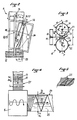
- Figure 2 shows a partial top view of the ginning station of the installation of Figure 1.
- FIG. 3 shows a sectional view along the axis III-III of the device of FIG. 2.
- FIG. 4 schematically shows a top view of the “lapper spreader” device of the installation of the present invention shown in FIG. 1.
- FIG. 5 shows the structure of the ply at the outlet of the lapper spreader shown in FIG. 4.
- Figures 6a to 6c schematically show the principle of formation of the sheet as shown in Figure 5 in a lapping spreader station.
- Figure 7 shows a detail of the installation of Figure 1 and in particular the cleaning and defibration.
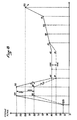
- FIG. 8 shows a diagram of the speeds of the sheet being treated in the various workstations of the installation shown in FIG. 1.
- the present invention relates to a process for the continuous preparation of plant stems as well as to an installation making it possible to implement said process.
- FIG. 1 An embodiment of said installation is shown as an example in FIG. 1.
- This installation allows the continuous preparation of plant stems and comprises the traditional stages of flax treatment, namely ginning, scutching and cleaning.
- a ply of stems is scoured, as illustrated by the arrows in FIG. 1.
- said stems are neither guided nor maintained, placed at least on two layers and arranged longitudinally in the direction of movement.
- the latter are arranged in a sheet so that they can be worked longitudinally from the core towards their extremities.
- the continuous preparation process makes it possible to work on a sheet set in motion in continuous advance.
- the tablecloth, along the path it travels, has two distinct configurations which will be called the first ply of stems and the second ply of stems.
- the rods are arranged perpendicular to the direction of advance of the tablecloth.
- the ply consists of rods arranged substantially parallel to the direction of advance of the ply.
- a first ply of rods (12) is formed, the structure of which is illustrated in particular at the station (3) in FIG. 1 or at the input of the station (6) in FIG. 4.
- the plant stems constituting it are arranged substantially parallel to each other and perpendicular to the direction of advance of the layer, shown diagrammatically by the arrow (13) in FIG. 6, and placed at least on one layer .
- the rods are arranged in this way and are wound on several layers of density "D1".
- the first layer is animated by a continuous advance movement at a speed "V1".
- the installation includes a dividing device whose input speed is "V1" and whose output speed is “V2" in order to allow a different density "D2".
- "D2" is greater than “D1” if "V2" is less than “V1” and conversely, the density “D2” is lower than that "D1” if the output speed "V2" is greater than the input speed "V1".
- the essential phase of work on said first ply (12) consists in eliminating the seeds and seed holders from the stems in a ginning device (4) capable of working the stems forming said first ply (12) transversely to the direction of advance (13) of said ply (12).
- FIGS. 2 and 3 show in detail an embodiment of an element of said ginner FR-A-2,562,916, and reference should be made to this document.
- FIG. 2 represents a set of drums (14) and (15) which are rotated in opposite directions but at the same speed by any known means around their axes (16) and (17) which are located in the same vertical plane "P" as shown in Figure 3.
- the rods constituting said first ply (12) continuously advance by pinching between strands facing a set of endless belts (18, 19) extending perpendicular to the rods whose direction of movement is designated by "F1" marked by the arrow (13).
- Figure 2 shows only one set of drums.
- the device (4) consists of several assemblies as shown schematically in Figure 1, which allow on the one hand to work the ends of upper rods to shell and remove the seed holders, and the feet to soften them .
- the inclination "A" is oriented in a direction such that, from the entry to the exit of the ginning device (4), the projection on the web (12) of the axes (16) and (17) of the drums (14) and (15) progressively approaches the ends (21) of the stems to prepare the stems of the heart towards their ends as the stems advance.
- each of the drums (14) and (15) carries blades (22, 23) cooperating with each other to impart a slight curvature (24) to the rods due to their arrangement and their relative rotation, in order to prepare the stems without breaking them and crushing the tablecloth (12).
- the blades (22, 23) are angularly spaced from each other by angles "B1", “B2” such that the edges of said blades are spaced from each other by a distance "E1", “E2 "very much higher than their maximum thickness "e”.
- the blades (22, 23) are out of phase from one drum to another in order to always pass at a certain distance from each other.
- the axes (17) and (16) of the drums are spaced from each other by a distance "X” such that the edge of a blade (22) located in the plane “P" of the axes (16, 17) enters between the edges of the blades (23) of the other drum only a distance "Y” just sufficient to impart a slight curvature (24) to the rods constituting the ply (12), which, however, pass with a certain clearance "J" above the side face of this other drum.
- X the edge of a blade (22) located in the plane "P" of the axes (16, 17) enters between the edges of the blades (23) of the other drum only a distance "Y” just sufficient to impart a slight curvature (24) to the rods constituting the ply (12), which, however, pass with a certain clearance "J" above the side face of this other drum.
- the blades are arranged in a helical pitch, opposite from one drum to the other, and inclined relative to the axis drums with an angle equal to "C" substantially corresponding to the angle "A".
- the stems of the tablecloth have their ends, head and foot, perfectly softened and devoid of seeds, seed carriers and roots.
- the scutching operation can then be carried out.
- a second ply (25) of rods is formed, from said first ply (12), which is animated with a continuous advance movement, shown diagrammatically. by the arrows (26) in Figures 1 and 4, substantially perpendicular to that of the first ply.
- said rods forming the second ply (25) are arranged substantially parallel to each other and parallel to the direction of advance of the second layer and placed at least on two layers.
- the first ply (12) is guided on a first support surface (27) then the end (28) of said ply (12) is forced in a periodic movement back and forth and it is deposited the rods on a second support surface (29) in continuous movement whose direction of movement (26) is perpendicular to that (13) of the first support surface (27).
- said rods making up the new ply known as the second ply (25) are arranged substantially parallel to one another on the support surface (29), and given the advance movement of the latter, the rods are placed in a zigzag pattern on at least two layers.
- Figures 4 and 5 show in particular the arrangement of the rods in the first ply and said second ply.
- the arrangement of the rods longitudinally in the direction of the second ply (25) on at least two layers is particularly advantageous because it gives a certain homogeneity of mass to the ply in order to improve the subsequent treatment thereof.
- the tablecloth at the end, is preferably formed by two layers of tiles. The sliding of the coating is carried out by overlap and it is necessary to achieve an overlap of the order of 50% otherwise there would be significant differences in density.
- the present inventors have thought of using such a device, initially intended for another application, with the aim of obtaining a different result, namely the pivoting of rods arranged parallel to each other transversely to their direction of advance, in order to then place them. in the longitudinal direction of movement, this also on at least layers arranged like tiles to allow the relative sliding of the tiles and favor the thinning of the sheet.
- FIGS. 6 illustrate the operating principle of a spreader-lapper device which has given good results in the application to the transfer of flax stalks.
- first load-bearing surface constituted in particular by an endless conveyor belt (27) capable of supporting the sheet (12) and of moving it according to the direction of advance (13), as well as a second load-bearing surface constituted by another endless belt conveyor (29) animated by a forward movement illustrated by the arrow (26) substantially perpendicular to that (13) of the conveyor (27).
- This second conveyor (29) is able to receive the second ply of rods (25) arranged longitudinally on at least two layers.
- the first guide mats (30) and second guide mats (31) are arranged so as to form a guide channel (34), this up to the end (28) of said first tablecloth (12).
- Figures 6a to 6c show three positions corresponding for example to the outward stroke.
- the second carriage (33) is located at the lateral end of the ply (25) and in FIG. 6c, the carriage (33) is at the opposite end.
- the width "Lf" of the second ply (25) is thus defined by the stroke of the carriage (33).
- the input speeds "Ve” and output speeds “Vs” determine the number of folds "Np” and implicitly the density “Ds" of said second sheet.
- FIG. 8 represents a speed diagram (in meters per minute) at the various stations of the installation of FIG. 1.
- said second sheet (25) At the end of this formation of said second sheet (25), it is then directed successively to the grinding station (8) then to the inclined cleaner station (9) in which the sheet is cleaned and separated. impurities, then to the defibration station (10) in order to deliver a veil of textile fibers suitable for use on woolen material.
- the grinding station (8) it will advantageously be formed from known devices and will in particular be constituted by a set of eight pairs of grooved rollers in treated steel, the lower rollers being mounted on fixed bearings and the upper rollers being mobile, mounted on slide bearings and kept under pressure by double-acting pneumatic cylinder.
- a fiber transfer conveyor belt is provided between each group of rollers of the grinding device (8).
- This strip will preferably have a width at least greater than that of the straw stems for avoid cracking of the fibers by the difference in speed of the mills.
- an inclined transfer conveyor belt is used for the automatic feeding of the cleaning element (9).
- Figure 7 shows the cleaning and defibration part of the installation.
- the cleaning station (9) comprises at its entrance a magnetic system for eliminating the metal parts found in the sheet thus worked, then comprises several drums with conical bats (35).
- the fine and high-speed sheet leaving the mills is introduced into the drum cleaner without condensation or slowing down, which allows better separation of shives and dust.
- the defibration assembly is composed of a first module (36) called a "opener defibrator" module constituted as input in a traditional manner by a hedgehog roller working at adjustable pressure, followed by an opener drum (37) equipped moats furnished with a multitude of inclined points, followed by a combing drum (38) also equipped with a moat furnished with a multitude of inclined points.
- a first module 36) called a "opener defibrator” module constituted as input in a traditional manner by a hedgehog roller working at adjustable pressure, followed by an opener drum (37) equipped moats furnished with a multitude of inclined points, followed by a combing drum (38) also equipped with a moat furnished with a multitude of inclined points.
- the second part of the defibration station (10) comprises a module called "opener finisher” (39) provided with one or more working elements with stripper comprising a first opening drum (40) equipped with staves furnished with a plurality of inclined points , followed by a second combing drum (41) also equipped with staves furnished with inclined points.
- the working machines are equipped with a dust collection and continuous discharge of waste to eliminate it.
- a hydraulic baler (11) of high power is provided, equipped with a pressure plate capable of making bales with the fibers delivered, as well as an automatic ligating system for strapping the said fibers. bullets.
- a machine of this type is also known to those skilled in the art.
Landscapes
- Engineering & Computer Science (AREA)
- Mechanical Engineering (AREA)
- Textile Engineering (AREA)
- Preliminary Treatment Of Fibers (AREA)
- Fertilizers (AREA)
- Breeding Of Plants And Reproduction By Means Of Culturing (AREA)
- Apparatuses For Bulk Treatment Of Fruits And Vegetables And Apparatuses For Preparing Feeds (AREA)
- Paper (AREA)
Claims (10)
- Verfahren zur Vorbereitung von Planzenstengeln, die Bastfasern, wie Flachs, Hanf, erzeugen, Verfahren während dessen die Stengel mindestens einer Dreschungsstufe, über eine Dreschvorrichtung (4), und einer Pochstufe, über eine Pochvorrichtung (8), ausgesetzt werden, dadurch gekennzeichnet, daß:- ein Tuch (25) von Stengeln, die während einer Dreschungsstufe vorher aufbereitet worden sind, gebildet wird, in dem die genannten Stengel im wesentlichen gleichlaufend zu einander und in Längsrichtung der Bewegung des genannten Tuchs (25) angeordnet sind, und eine Ziegelformgebung der Stengel sowie ein Übereinandergleiten der Ziegel vorgenommen wird, damit die genannten Stengel in mindestens zwei Schichten vorgesehen werden,- dem genannten Stengeltuch (25) eine kontinuierliche Vorschubbewegung (26) verleiht und das also gebildete Tuch (25) zu einer Pochvorrichtung (8) geleitet wird, zum Verarbeiten in der Länge der Stengel in der Vorschubrichtung des Tuchs (25).
- Verfahren nach Anspruch 1, dadurch gekennzeichnet, daß:- vor der Dreschungsstufe ein erstes Stengeltuch (12) gebildet wird, in dem die genannten Stengel im wesentlichen gleich-laufend zu einander und senkrecht zur Vorschubrichtung des genannten ersten Tuchs angeordnet und in einer oder mehreren Schichten vorgesehen werden,- dem genannten ersten Tuch über eine erste Tragfläche (27) eine kontinuierliche Vorschubbewegung (13) verleiht wird,- das genannte ziegelförmige Tuch, das "zweites Tuch" (25) genannt wird, über eine Vorrichtung (6), die "Ausbreitungs- und Tuchbildungsvorrichtung" genannt wird, ab den Stengeln des ersten Tuchs (12), das von der ersten Tragfläche (27) in Bewegung gebracht wird, gebildet wird, wonach dem Ende (28) des Tuchs (12) eine periodische Hin- und Herbewegung verleiht wird und dadurch, daß die Stengel zickzackweise auf eine zweite kontinuierlich bewegende Tragfläche (29) gelegt werden, deren Vorschubrichtung (26) senkrecht zu der (13) der ersten Tragfläche (27) ist.
- Verfahren nach Anspruch 2, dadurch gekennzeichnet, daß das genannte erste Stengeltuch (12) ab einer Rolle geernteter Stengel gebildet wird und die Dichte "De" des genannten Tuchs (12) über Vorrichtungen (5) eingestellt wird, die geeignet sind, die Geschwindigkeit "Ve" des Tuchs (12) nach dem Abrollen zu ändern.
- Verfahren nach Anspruch 2, dadurch gekennzeichnet, daß die das erste Tuch (12) bildenden Stengel mittels eines Satzes (4) von Trommeln (14, 15) aufbereitet werden, die geeignet sind, die Stengel in der Längsrichtung, vom Kern zu deren Enden hin, zu schaben, ohne sie zu brechen oder das Tuch zu zerquetschen.
- Verfahren nach Anspruch 1, dadurch gekennzeichnet, daß auf dem genannten homogenen Tuch (25) nacheinanderfolgend in der Linie die Behandlung mittels Brecher (8), danach die Reinigung des Tuchs mittels geneigter Reiniger (9), anschließend das Schleifen mittels eines "Brechtrommels" (36) und "Fertigungstrommeln" (39) durchgeführt werden, zum Liefern eines Textilfaservlieses, das geeignet ist, auf einem Wollmaterial verwendet zu werden.
- Anlage zur Aufbereitung von Planzenstengeln, die die Anwendung des Verfahrens nach Anspruch 1 erlaubt, umfassend mindestens nacheinanderfolgend eine Dreschvorrichtung (4) und eine Pochvorrichtung (8), dadurch gekennzeichnet, daß sie umfaßt:- Mittel (27, 6) zum Bilden eines Stengeltuchs (25), in dem die genannten Stengel im wesentlichen gleichlaufend zu einander und in Längsrichtung der Bewegung des genannten Tuchs angeordnet sind, und zum Durchführen einer Ziegelformgebung der Stengel sowie einer Aufeinanderschiebung der Ziegel, damit die genannten Stengel in mindestens zwei Schichten vorgesehen werden,- Mittel (29) zum Befördern des genannten Tuchs (25) gemäß einer kontinuierlichen Vorschubbewegung und zum Unterwerfen der genannten Stengel, mindestens in zwei Schichten, in der Längsrichtung der Bewegung (26), an der Pochvorrichtung (8), die mindestens Brechwerkzeuge aufweist, zum Verarbeiten in der Länge der Stengel in der Vorschubrichtung (26) des Tuchs (25).
- Anlage nach Anspruch 6, dadurch gekennzeichnet, daß sie umfaßt:- Mittel zum Bilden eines ersten Stengeltuchs (12), die stromaufwärts der genannten Mittel (6) zum Bilden des genannten ziegelförmigen Tuchs (25) angeordnet sind, zum Erzeugen eines Stengeltuchs (12), das über eine erste Tragfläche (27) kontinuierlich in Bewegung ist, wobei die genannten Stengel im wesentlichen gleichlaufend zu einander und in Längsrichtung der Bewegung (13) des Tuchs angeordnet und in einer oder mehreren Schichten vorgesehen werden,- Mittel zum Bilden des genannten ziegelförmigen Tuchs, das zweites Tuch (25) genannt wird, die aus einer "Ausbreitungs- und Tuchbildungsvorrichtung" (6) bestehen, die, ab den Stengeln des ersten Tuchs (12), das über die erste Tragfläche (27) in Bewegung ist, das Ende (28) des Tuchs (12) einer periodischen Hin- und Herbewegung aussetzt und es erlaubt, die Stengel zickzackweise auf eine zweite kontinuierlich bewegende Tragfläche (29) zu legen, deren Vorschubrichtung (26) senkrecht zu der (13) der ersten Tragfläche (27) ist.
- Anlage nach Anspruch 7, dadurch gekennzeichnet, daß sie Mittel umfaßt, um das genannte erste Tuch (12) gemäß einer kontinuierlichen Vorschubbewegung (13) zu führen und die genannten Stengel der Dreschvorrichtung (4) zu unterwerfen, um die Stengel quer zur Vorschubrichtung des genannten ersten Tuchs (12) zu verarbeiten.
- Anlage nach Anspruch 6, dadurch gekennzeichnet, daß sie nacheinander mindestens eine Ballenabrollvorrichtung (2), eine Dreschvorrichtung (4) und eine Aufteilvorrichtung (5), die es erlaubt, die Dichte des Tuchs (12) am Eintritt der genannten Mittel (6) einzustellen, umfaßt.
- Anlage nach Anspruch 6, dadurch gekennzeichnet, daß sie stromabwärts der genannten Mittel (6) zum Bilden eines homogenen Tuchs (25) mindestens einen Brechstand (8), eine geneigte Reinigungsvorrichtung (9) und eine Schleifvorrichtung (10) umfaßt.
Priority Applications (1)
| Application Number | Priority Date | Filing Date | Title |
|---|---|---|---|
| AT87402990T ATE90743T1 (de) | 1987-11-19 | 1987-12-24 | Verfahren und vorrichtung zur kontinuierlichen aufbereitung von pflanzenstengeln. |
Applications Claiming Priority (2)
| Application Number | Priority Date | Filing Date | Title |
|---|---|---|---|
| FR8716304 | 1987-11-19 | ||
| FR8716304A FR2623527B1 (fr) | 1987-11-19 | 1987-11-19 | Procede de preparation en continu de tiges de vegetaux et installation de preparation permettant la mise en oeuvre dudit procede |
Publications (2)
| Publication Number | Publication Date |
|---|---|
| EP0317681A1 EP0317681A1 (de) | 1989-05-31 |
| EP0317681B1 true EP0317681B1 (de) | 1993-06-16 |
Family
ID=9357129
Family Applications (1)
| Application Number | Title | Priority Date | Filing Date |
|---|---|---|---|
| EP87402990A Expired - Lifetime EP0317681B1 (de) | 1987-11-19 | 1987-12-24 | Verfahren und Vorrichtung zur kontinuierlichen Aufbereitung von Pflanzenstengeln |
Country Status (4)
| Country | Link |
|---|---|
| EP (1) | EP0317681B1 (de) |
| AT (1) | ATE90743T1 (de) |
| DE (1) | DE3786267T2 (de) |
| FR (1) | FR2623527B1 (de) |
Cited By (1)
| Publication number | Priority date | Publication date | Assignee | Title |
|---|---|---|---|---|
| WO2024251769A1 (de) * | 2023-06-05 | 2024-12-12 | Andritz Küsters Gmbh | Verfahren und anlage zum herstellen von verspinnbaren bastfasern bzw. eines bastfadens |
Families Citing this family (16)
| Publication number | Priority date | Publication date | Assignee | Title |
|---|---|---|---|---|
| BE1003727A3 (fr) * | 1988-09-13 | 1992-06-02 | Claas Saulgau Gmbh | Procede et dispositif pour la recolte et la preparation de lin. |
| DE3923498A1 (de) * | 1989-07-15 | 1991-01-17 | Jakob Bahmer | Verfahren und vorrichtung zum entholzen und zum aufbereiten von flachs |
| GB9118932D0 (en) * | 1991-09-05 | 1991-10-23 | Mini Agriculture & Fisheries | Fiore separating machine |
| US6079647A (en) * | 1996-07-19 | 2000-06-27 | Durafibre Inc. | Plant material processing system |
| DE19841092A1 (de) * | 1998-09-09 | 2000-03-16 | Heinen Rauchtabaktechnik Gmbh | Verfahren und Vorrichtung zum Aufbereiten von Faserpflanzenmaterial |
| FR2810997B1 (fr) * | 2000-06-28 | 2002-09-20 | Louis Hurdequint | Perfectionnement aux dispositifs de traitement des fibres liberiennes |
| RU2179205C1 (ru) * | 2000-07-10 | 2002-02-10 | Открытое акционерное общество "Костромское специальное конструкторское бюро текстильных машин" | Устройство для очистки промятых стеблей лубяных культур |
| RU2233917C1 (ru) * | 2003-10-13 | 2004-08-10 | Костромской государственный технологический университет | Способ получения длинного лубяного волокна |
| RU2306371C2 (ru) * | 2005-09-22 | 2007-09-20 | Открытое акционерное общество "Центральный научно-исследовательский институт комплексной автоматизации легкой промышленности" (ОАО "ЦНИИЛКА") | Способ получения трепанием длинного льняного волокна из слоя промятой тресты |
| RU2318929C1 (ru) * | 2006-05-22 | 2008-03-10 | ФГОУ ВПО Костромская государственная сельскохозяйственная академия | Устройство для съема тресты льняной с транспортера сушилки |
| RU2324022C1 (ru) * | 2006-08-14 | 2008-05-10 | Государственное научное учреждение "Всероссийский научно-исследовательский институт по переработке лубяных культур" Российской академии сельскохозяйственных наук | Мяльно-трепальный станок для выделения волокна из стеблей тресты лубяных культур |
| RU193793U1 (ru) * | 2019-06-19 | 2019-11-15 | Федеральное государственное бюджетное образовательное учреждение высшего образования "Костромская государственная сельскохозяйственная академия" | Мяльно-трепальный станок для выделения волокна из стеблей тресты лубяных культур |
| RU201183U9 (ru) * | 2020-08-26 | 2021-02-17 | Федеральное государственное бюджетное научное учреждение "Федеральный научный центр лубяных культур" (ФГБНУ ФНЦ ЛК") | Мяльно-трепальный станок для выделения волокна из льнотресты |
| CN112522793B (zh) * | 2020-11-30 | 2021-12-03 | 艾百合纺织科技(安徽)有限公司 | 纤维原料牵引设备 |
| WO2025093439A1 (fr) * | 2023-10-30 | 2025-05-08 | Andritz Asselin-Thibeau | Etaleur nappeur a trois tapis |
| FR3154736B1 (fr) * | 2023-10-30 | 2025-10-17 | Andritz Asselin Thibeau | Etaleur nappeur à trois tapis |
Family Cites Families (4)
| Publication number | Priority date | Publication date | Assignee | Title |
|---|---|---|---|---|
| DE423361C (de) * | 1926-01-07 | Constantin Vansteenkiste | Maschine zum Entholzen und Geschmeidigmachen von Faserstengeln | |
| FR675749A (fr) * | 1929-05-24 | 1930-02-13 | Procédé et appareil pour le traitement de matière fibreuse | |
| US2551855A (en) * | 1944-12-20 | 1951-05-08 | John N Selvig | Apparatus for treating fibrous stalks |
| NL7809836A (nl) * | 1977-09-30 | 1979-04-03 | Inst Textile De France | Werkwijze voor het vormen van een doorlopende laag bastvezels en inrichting voor het uitvoeren daarvan. |
-
1987
- 1987-11-19 FR FR8716304A patent/FR2623527B1/fr not_active Expired - Fee Related
- 1987-12-24 DE DE87402990T patent/DE3786267T2/de not_active Expired - Fee Related
- 1987-12-24 AT AT87402990T patent/ATE90743T1/de not_active IP Right Cessation
- 1987-12-24 EP EP87402990A patent/EP0317681B1/de not_active Expired - Lifetime
Cited By (1)
| Publication number | Priority date | Publication date | Assignee | Title |
|---|---|---|---|---|
| WO2024251769A1 (de) * | 2023-06-05 | 2024-12-12 | Andritz Küsters Gmbh | Verfahren und anlage zum herstellen von verspinnbaren bastfasern bzw. eines bastfadens |
Also Published As
| Publication number | Publication date |
|---|---|
| DE3786267D1 (de) | 1993-07-22 |
| ATE90743T1 (de) | 1993-07-15 |
| DE3786267T2 (de) | 1994-02-03 |
| FR2623527A1 (fr) | 1989-05-26 |
| FR2623527B1 (fr) | 1991-04-26 |
| EP0317681A1 (de) | 1989-05-31 |
Similar Documents
| Publication | Publication Date | Title |
|---|---|---|
| EP0317681A1 (de) | Verfahren und Vorrichtung zur kontinuierlichen Aufbereitung von Pflanzenstengeln | |
| BE1004370A4 (fr) | Installation pour le teillage et la preparation du lin. | |
| FR2620896A1 (fr) | Dispositif de recolte des plantes a fibres notamment du lin, avec battage des graines et extraction sommaire de la fibre au champ | |
| EP0209410B1 (de) | Verfahren und Vorrichtung zum schwingenden Flachsbrechen | |
| CH616182A5 (de) | ||
| EP1589132B1 (de) | Karde mit einer drehbaren Absaugübertragungsvorrichtung | |
| EP0517635B1 (de) | Krempel | |
| FR2582296A1 (fr) | Procede et dispositif de fabrication de produits en fibres de verre, tels que nappes, mats, files et meches | |
| EP1318217A1 (de) | Karde mit einem Akkumulator-Übertragungszylinder | |
| FR2676754A1 (fr) | Procede et dispositif de traitement par brossage d'une nappe de tiges de plantes a fibres, notamment de lin. | |
| CN115233318B (zh) | 一种麻类韧皮纤维非碎茎法湿剥整骨分离机及分离工艺 | |
| EP0380635A1 (de) | Verfahren zum offenend-spinnen und vorrichtung zur durchführung dieses verfahrens | |
| FR2903124A1 (fr) | Dispositif de traitement par brossage d'une nappe de tiges de plantes a fibres,notamment de lin | |
| BE523611A (de) | ||
| BE520237A (de) | ||
| BE533565A (de) | ||
| BE469613A (de) | ||
| BE515944A (de) | ||
| BE435113A (de) | ||
| BE542813A (de) | ||
| CZ283196B6 (cs) | Způsob kotonizace lněné koudele a zařízení k provádění tohoto způsobu | |
| BE701175A (de) | ||
| BE503689A (de) | ||
| BE449186A (de) | ||
| BE447320A (de) |
Legal Events
| Date | Code | Title | Description |
|---|---|---|---|
| PUAI | Public reference made under article 153(3) epc to a published international application that has entered the european phase |
Free format text: ORIGINAL CODE: 0009012 |
|
| AK | Designated contracting states |
Kind code of ref document: A1 Designated state(s): AT BE CH DE ES GB GR IT LI LU NL SE |
|
| 17P | Request for examination filed |
Effective date: 19890615 |
|
| 17Q | First examination report despatched |
Effective date: 19910412 |
|
| GRAA | (expected) grant |
Free format text: ORIGINAL CODE: 0009210 |
|
| AK | Designated contracting states |
Kind code of ref document: B1 Designated state(s): AT BE CH DE ES GB GR IT LI LU NL SE |
|
| PG25 | Lapsed in a contracting state [announced via postgrant information from national office to epo] |
Ref country code: SE Effective date: 19930616 Ref country code: GR Free format text: LAPSE BECAUSE OF FAILURE TO SUBMIT A TRANSLATION OF THE DESCRIPTION OR TO PAY THE FEE WITHIN THE PRESCRIBED TIME-LIMIT Effective date: 19930616 Ref country code: GB Effective date: 19930616 Ref country code: AT Effective date: 19930616 |
|
| REF | Corresponds to: |
Ref document number: 90743 Country of ref document: AT Date of ref document: 19930715 Kind code of ref document: T |
|
| REF | Corresponds to: |
Ref document number: 3786267 Country of ref document: DE Date of ref document: 19930722 |
|
| ITF | It: translation for a ep patent filed | ||
| PG25 | Lapsed in a contracting state [announced via postgrant information from national office to epo] |
Ref country code: ES Free format text: LAPSE BECAUSE OF FAILURE TO SUBMIT A TRANSLATION OF THE DESCRIPTION OR TO PAY THE FEE WITHIN THE PRESCRIBED TIME-LIMIT Effective date: 19930927 |
|
| GBV | Gb: ep patent (uk) treated as always having been void in accordance with gb section 77(7)/1977 [no translation filed] |
Effective date: 19930616 |
|
| PG25 | Lapsed in a contracting state [announced via postgrant information from national office to epo] |
Ref country code: LU Free format text: LAPSE BECAUSE OF NON-PAYMENT OF DUE FEES Effective date: 19931231 Ref country code: LI Effective date: 19931231 Ref country code: CH Effective date: 19931231 |
|
| PLBE | No opposition filed within time limit |
Free format text: ORIGINAL CODE: 0009261 |
|
| STAA | Information on the status of an ep patent application or granted ep patent |
Free format text: STATUS: NO OPPOSITION FILED WITHIN TIME LIMIT |
|
| 26N | No opposition filed | ||
| REG | Reference to a national code |
Ref country code: CH Ref legal event code: PL |
|
| PGFP | Annual fee paid to national office [announced via postgrant information from national office to epo] |
Ref country code: NL Payment date: 19961231 Year of fee payment: 10 Ref country code: DE Payment date: 19961231 Year of fee payment: 10 |
|
| PGFP | Annual fee paid to national office [announced via postgrant information from national office to epo] |
Ref country code: BE Payment date: 19970214 Year of fee payment: 10 |
|
| PG25 | Lapsed in a contracting state [announced via postgrant information from national office to epo] |
Ref country code: BE Free format text: LAPSE BECAUSE OF NON-PAYMENT OF DUE FEES Effective date: 19971231 |
|
| BERE | Be: lapsed |
Owner name: S.A. LIN DEVELOPPEMENT Effective date: 19971231 |
|
| PG25 | Lapsed in a contracting state [announced via postgrant information from national office to epo] |
Ref country code: NL Free format text: LAPSE BECAUSE OF NON-PAYMENT OF DUE FEES Effective date: 19980701 |
|
| NLV4 | Nl: lapsed or anulled due to non-payment of the annual fee |
Effective date: 19980701 |
|
| PG25 | Lapsed in a contracting state [announced via postgrant information from national office to epo] |
Ref country code: DE Free format text: LAPSE BECAUSE OF NON-PAYMENT OF DUE FEES Effective date: 19980901 |
|
| PG25 | Lapsed in a contracting state [announced via postgrant information from national office to epo] |
Ref country code: IT Free format text: LAPSE BECAUSE OF NON-PAYMENT OF DUE FEES;WARNING: LAPSES OF ITALIAN PATENTS WITH EFFECTIVE DATE BEFORE 2007 MAY HAVE OCCURRED AT ANY TIME BEFORE 2007. THE CORRECT EFFECTIVE DATE MAY BE DIFFERENT FROM THE ONE RECORDED. Effective date: 20051224 |