EP0317733A1 - Verfahren und Vorrichtung zum Greifen des Endes einer Vorgarnlunte, eines Garns oder dgl. an einer Spule und Transport der Faserlunte oder des Garns zu einer vorbestimmten Position - Google Patents
Verfahren und Vorrichtung zum Greifen des Endes einer Vorgarnlunte, eines Garns oder dgl. an einer Spule und Transport der Faserlunte oder des Garns zu einer vorbestimmten Position Download PDFInfo
- Publication number
- EP0317733A1 EP0317733A1 EP88115795A EP88115795A EP0317733A1 EP 0317733 A1 EP0317733 A1 EP 0317733A1 EP 88115795 A EP88115795 A EP 88115795A EP 88115795 A EP88115795 A EP 88115795A EP 0317733 A1 EP0317733 A1 EP 0317733A1
- Authority
- EP
- European Patent Office
- Prior art keywords
- roving
- cop
- hollow body
- elongated hollow
- yarn
- Prior art date
- Legal status (The legal status is an assumption and is not a legal conclusion. Google has not performed a legal analysis and makes no representation as to the accuracy of the status listed.)
- Ceased
Links
- 238000000034 method Methods 0.000 title claims abstract description 16
- 238000007664 blowing Methods 0.000 claims abstract description 3
- 230000000694 effects Effects 0.000 claims description 12
- 238000011144 upstream manufacturing Methods 0.000 claims description 4
- 239000004753 textile Substances 0.000 description 4
- 238000004891 communication Methods 0.000 description 1
- 238000005096 rolling process Methods 0.000 description 1
- 238000009987 spinning Methods 0.000 description 1
Images

Classifications
-
- D—TEXTILES; PAPER
- D01—NATURAL OR MAN-MADE THREADS OR FIBRES; SPINNING
- D01H—SPINNING OR TWISTING
- D01H13/00—Other common constructional features, details or accessories
- D01H13/04—Guides for slivers, rovings, or yarns; Smoothing dies
- D01H13/045—Guide tube
-
- B—PERFORMING OPERATIONS; TRANSPORTING
- B65—CONVEYING; PACKING; STORING; HANDLING THIN OR FILAMENTARY MATERIAL
- B65H—HANDLING THIN OR FILAMENTARY MATERIAL, e.g. SHEETS, WEBS, CABLES
- B65H67/00—Replacing or removing cores, receptacles, or completed packages at paying-out, winding, or depositing stations
- B65H67/08—Automatic end-finding and material-interconnecting arrangements
-
- B—PERFORMING OPERATIONS; TRANSPORTING
- B65—CONVEYING; PACKING; STORING; HANDLING THIN OR FILAMENTARY MATERIAL
- B65H—HANDLING THIN OR FILAMENTARY MATERIAL, e.g. SHEETS, WEBS, CABLES
- B65H2701/00—Handled material; Storage means
- B65H2701/30—Handled filamentary material
- B65H2701/31—Textiles threads or artificial strands of filaments
Definitions
- the present invention concerns a method and a device to take the end of a roving, yarn or the like from a cop and carry it to a predetermined position, for example in correspondence with a textile machine, such as a spinner, in a completely automatic way.
- the technique of machine feed envisages that the operation of seizing the end of the roving, yarn or the like from the cop and carrying it to a grasping device in the textile machine (for instance, the drawing rolling mill of a spinning machine), simultaneously unwinding part of said roving or similar, is performed almost completely manually.
- An object of the present invention is to provide a method capable of solving the abovesaid problems, automating the operation of drawing the end of a roving, yarn or the like from a cop and carrying it to a predetermined position on a textile machine.
- Another object of the present invention is to provide a device allowing to automate said operation of drawing and carrying the end of a roving, yarn or similar.
- the present invention concerns a method for grasping the end of a roving, yarn or the like from a cop and transferring it to a predetermined position, characterized in that it comprises the steps of: positioning an elongated hollow body between the area of the cop where the end of roving or the like is present and said predetermined position; detaching said end from the cop and positioning it near the entry of said elongated hollow body; drawing said end inside said elongated body by means of a pneumatic effect generated in said body by one or more blowing and/or sucking jets of air or other gas; feeding said end along the whole elongated hollow body up to said predetermined position, pushing it by means of said jets and by means of possible additional pushing jets; opening and removing the elongated hollow body.
- the invention concerns a device to grasp the end of a roving, yarn or the like and send it to a predetermined position, characterized in that it comprises an elongated hollow body inside which one or more ducts feeding air or other gas are provided, said ducts creating, when fed, such a negative and/or positive pressure in the body cavity, to be able of moving forward along the same, a roving, yarn or the like, and in that said body can be opened to free the roving or yarn when moved forward.
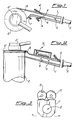
- an elongated hollow body 1 is positioned between a cop 2, supported by an arm 2′, and a preset position represented by the month of a guide tube 3. Contrary to said cop 2 and said guide tube 3, the hollow body 1 is represented in section in order to make the structure more comprehensible.
- said body 1 defines a main duct on the side walls of which there are provided secondary ducts 4 adapted to put the external environment in communication with the inner cavity 5 of said hollow body 1.
- Said ducts 4 can be connected to a compressed air source or to a source of other compressed gas (not illustrated), and their position with respect to the walls of the hollow body 1 is such that, when fed with said gas, they create a Venturi effect inside said hollow body 1.
- the Venturi effect causes a depression upstream the outlet openings 6 of ducts 4 within the cavity 5 and a pressure downstream said openings 6.
- Another duct 7 (connectable as well to a source of air or gas under pressure) is provided at the month of the elongated body 1, said month showing a particular asymmetrical shape, following the configuration of the side surface of the cop 2, starting from a position of substantial tangency to the same.
- the angled position of the internal lip of said month serves to place the duct 7 in such a way that the air jet coming out from the same results tangentially directed to the cop 2; in this way said jet coming from duct 7, during the cop rotation can raise the roving or yarn end 8, detach it from the cop 2 and position it approximately in the central area of said mouth.
- the roving is positioned in a seat 8′ provided in the upper edge of the bobbin; by slightly forcing the rowing end 8 into said seat 8′, it is possible to obtain its stable positioning under normal conditions, and its easy detachment, thanks to the jet from duct 7, when the cop has to be unwound.
- the hollow body 1 has an additional duct 9, always connected to a source of air or other gas under pressure; said duct, when fed with said gas, provides an additional pushing jet to feed the roving end beyond the elongated body 1, for example in the guide tube 3 of figures 1 and 2.
- Figure 3 shows a preferential embodiment, wherein the body 1 is formed by two halves hinged to each other along the upper side. Said halves can rotate around said hinged side under the control of a motor and a series of gears; in figure 3, motor and gears are diagrammatically shown by reference 11.
- FIGS 4, 5 and 6 show an alternative embodiment of the elongated body 1 according to the invention.
- the parts which are unchanged with respect to the preceding figures are indicated by the same references.
- the ducts 4 are substituted by a single duct 12, placed in a more advanced position with respect to the body mouth and extending inside the hollow body 1′ thanks to a groove 13 provided on the internal surface of said hollow body.
- ducts variable in number and position, provided that they give a pneumatic effect of suction and/or push for the roving or yarn inside the body 1.
- an alternative device for the mechanical detachment of the roving end 8 is also illustrated, said device being obtained by replacing the duct 7 with a pin 14 or similar element, which in rest conditions is at least partly housed in a seat provided in said entry of body 1′ and that from same is partially removable and can be inserted into the seat 8′ to mechanically detach the roving end during the cop rotation.
- a pin 14 or similar element which in rest conditions is at least partly housed in a seat provided in said entry of body 1′ and that from same is partially removable and can be inserted into the seat 8′ to mechanically detach the roving end during the cop rotation.
- the end 8 is positioned inside the body entry.
- the duct 9′ is different from the corresponding duct 9 of figure 2; in fact said duct 9′ does not enters the cavity 5 of elongated body 1′, but ends outside and parallely to said cavity with a final section 9 ⁇ , though remaining in the vicinity of the cavity end.
- figure 6 shows a different mechanism to open the elongated body 1, wherein one of the two halves forming said body is rotated as far as to be essentially parallel to the remaining part, so as to avoid any possible interference of the body 1′ with the roving during the removal of said body 1′ from the latter.
- the devices described above and illustrated in figures 1 to 6 are preferred embodiments which utilize a Venturi effect to carry said end 8 of the roving through the elongated hollow body.
- the elongated hollow body 1 is positioned with its mouth near the cop 2, similarly to what shown in figures 1 and 2.
- the cop 2 is then rotated in the direction of its unwinding (in the case illustrated in figures 1 and 2 the cop will rotate clockwise), preferably by means of a mechanism built for this purpose in the supporting arm 2′.
- the ducts 4, 7 and 9 are fed, taking care that the flow of duct 7 is such as not interfere with the Venturi effect generated by ducts 4.
- the jets coming from the ducts 4 cause a depression upstream of their outlets 6 and a pressure downstream of same; when the roving end 8 is brought by the cop 2 rotation in correspondence with the jet coming from duct 7, said end is raised and detached from the cop seat 8′ and carried approximately in the central area of said mouth. From here the roving end 8 is submitted to said depression caused by Venturi effect, is sucked towards the opposite side of the elongated body 1, reaching the openings 6 of ducts 4. Approximately in correspondence with said openings, the roving end 8 is submitted to pressure generated in the end part of body 1 by the jets coming from the same ducts 4 and is then carried up to the end of body 1.
- the jet coming from duct 9 provides the roving end 8 with an additional push necessary to remove it from body 1, and to convey it along the guide tube 3.
Landscapes
- Engineering & Computer Science (AREA)
- Mechanical Engineering (AREA)
- Textile Engineering (AREA)
- Spinning Or Twisting Of Yarns (AREA)
- Replacing, Conveying, And Pick-Finding For Filamentary Materials (AREA)
Applications Claiming Priority (2)
| Application Number | Priority Date | Filing Date | Title |
|---|---|---|---|
| IT2222387 | 1987-10-12 | ||
| IT22223/87A IT1222871B (it) | 1987-10-12 | 1987-10-12 | Procedimento e dispositivo per l'afferamento del capo di uno stoppino filato o simile da una bobina e per il suo invio ad una posizione prefissata |
Publications (1)
| Publication Number | Publication Date |
|---|---|
| EP0317733A1 true EP0317733A1 (de) | 1989-05-31 |
Family
ID=11193280
Family Applications (1)
| Application Number | Title | Priority Date | Filing Date |
|---|---|---|---|
| EP88115795A Ceased EP0317733A1 (de) | 1987-10-12 | 1988-09-26 | Verfahren und Vorrichtung zum Greifen des Endes einer Vorgarnlunte, eines Garns oder dgl. an einer Spule und Transport der Faserlunte oder des Garns zu einer vorbestimmten Position |
Country Status (4)
| Country | Link |
|---|---|
| US (1) | US5056728A (de) |
| EP (1) | EP0317733A1 (de) |
| JP (1) | JPH01122877A (de) |
| IT (1) | IT1222871B (de) |
Cited By (6)
| Publication number | Priority date | Publication date | Assignee | Title |
|---|---|---|---|---|
| EP0388680A3 (en) * | 1989-03-03 | 1990-10-10 | Kabushiki Kaisha Toyoda Jidoshokki Seisakusho | Weft processing apparatus in a jet loom |
| EP0482475A1 (de) * | 1990-10-22 | 1992-04-29 | Maschinenfabrik Rieter Ag | Wattenablöser |
| EP0498944A3 (en) * | 1991-02-09 | 1992-09-23 | August Herzog Maschinenfabrik Gmbh & Co. Kg | Braid condensing device |
| EP0677474A1 (de) * | 1994-04-14 | 1995-10-18 | SAVIO MACCHINE TESSILI S.r.l. | Verfahren zum Enfernen des gewickelten Garnendes, das zur Seite der sich im Entstehen befindlichen Spule fällt |
| US6282755B1 (en) | 1998-11-04 | 2001-09-04 | Rieter Ingolstadt Spinnereimaschinenbau Ag | Process and textile machine for feeding fiber slivers to drafting equipment |
| CN103572426A (zh) * | 2012-07-23 | 2014-02-12 | 株式会社丰田自动织机 | 用于纺纱机的气流清洁器 |
Families Citing this family (7)
| Publication number | Priority date | Publication date | Assignee | Title |
|---|---|---|---|---|
| DE19813515A1 (de) * | 1998-03-26 | 1999-10-07 | Zinser Textilmaschinen Gmbh | Vorrichtung zum Bewegen eines Fadens zu einer durch eine Friktionswalze angetriebenen Spulhülse |
| TW201221256A (en) * | 2010-11-23 | 2012-06-01 | Ind Tech Res Inst | Transmitting wire module |
| JP2014019989A (ja) * | 2012-07-23 | 2014-02-03 | Toyota Industries Corp | 紡機におけるニューマクリアラ装置 |
| DE102015112661A1 (de) * | 2015-07-31 | 2017-02-02 | Rieter Ingolstadt Gmbh | Verfahren an einer Textilmaschine und Textilmaschine |
| DE102015112660A1 (de) * | 2015-07-31 | 2017-02-02 | Rieter Ingolstadt Gmbh | Verfahren zum Absaugen eines Fadens von einer Spule und entsprechende Vorrichtung |
| US10969556B1 (en) * | 2017-04-24 | 2021-04-06 | NET Recycling, LLC | Method and apparatus for removing optic fiber from multiple spools |
| EP4015682B1 (de) * | 2020-12-18 | 2025-01-29 | Saurer Intelligent Technology AG | Arbeitsstelle einer luftspinnmaschine |
Citations (5)
| Publication number | Priority date | Publication date | Assignee | Title |
|---|---|---|---|---|
| FR1354027A (fr) * | 1963-04-25 | 1964-02-28 | Murata Machinery Ltd | Appareil automatique pour l'alimentation en cannettes d'un magasin de bobinoir |
| DE1214122B (de) * | 1961-03-21 | 1966-04-07 | Karl August Muellers | Spulautomat, insbesondere Kreuzspulautomat |
| GB1098134A (en) * | 1964-05-22 | 1968-01-03 | Mackie & Sons Ltd J | Improvements relating to textile drawing frames |
| US3754718A (en) * | 1971-08-30 | 1973-08-28 | Abbott Machine Co | End-finding means for yarn handling apparatus |
| GB2019450A (en) * | 1978-04-25 | 1979-10-31 | Hamel Gmbh Zwirnmaschinen | Uptwisting Machines |
Family Cites Families (9)
| Publication number | Priority date | Publication date | Assignee | Title |
|---|---|---|---|---|
| US2681729A (en) * | 1952-03-03 | 1954-06-22 | American Enka Corp | Removable air jet |
| US3108618A (en) * | 1960-03-03 | 1963-10-29 | Toyoda Automatic Loom Works | Bunch remover |
| US3236464A (en) * | 1962-02-03 | 1966-02-22 | Reiners Walter | Device for removing a starting length of yarn from a textile coil |
| GB1091249A (en) * | 1963-12-21 | 1967-11-15 | Reiners Walter | Method and apparatus for feeding supply packages to the winding stations of a thread winding machine |
| US3866848A (en) * | 1971-12-13 | 1975-02-18 | Abbott Machine Co | End finding nozzle |
| GB1440272A (en) * | 1972-10-17 | 1976-06-23 | Nihon Spindle Mfg Co Ltd | Apparatus for supplying cops to winder units of winding machines and for processing the yarn ends |
| DE2423493C2 (de) * | 1974-05-15 | 1983-03-24 | W. Schlafhorst & Co, 4050 Mönchengladbach | Vorrichtung zum pneumatischen Ablösen des Fadenfangs an rotierenden Textilspulen |
| DE3008640A1 (de) * | 1979-05-16 | 1980-11-20 | Schweiter Ag Maschf | Fadenabzugvorrichtung fuer textilspulen |
| EP0110359B1 (de) * | 1979-10-02 | 1988-06-22 | Maschinenfabrik Rieter Ag | Einfädeln von Garnbehandlungsdüsen |
-
1987
- 1987-10-12 IT IT22223/87A patent/IT1222871B/it active
-
1988
- 1988-09-26 EP EP88115795A patent/EP0317733A1/de not_active Ceased
- 1988-10-07 JP JP63252197A patent/JPH01122877A/ja active Pending
-
1990
- 1990-08-13 US US07/566,262 patent/US5056728A/en not_active Expired - Fee Related
Patent Citations (5)
| Publication number | Priority date | Publication date | Assignee | Title |
|---|---|---|---|---|
| DE1214122B (de) * | 1961-03-21 | 1966-04-07 | Karl August Muellers | Spulautomat, insbesondere Kreuzspulautomat |
| FR1354027A (fr) * | 1963-04-25 | 1964-02-28 | Murata Machinery Ltd | Appareil automatique pour l'alimentation en cannettes d'un magasin de bobinoir |
| GB1098134A (en) * | 1964-05-22 | 1968-01-03 | Mackie & Sons Ltd J | Improvements relating to textile drawing frames |
| US3754718A (en) * | 1971-08-30 | 1973-08-28 | Abbott Machine Co | End-finding means for yarn handling apparatus |
| GB2019450A (en) * | 1978-04-25 | 1979-10-31 | Hamel Gmbh Zwirnmaschinen | Uptwisting Machines |
Non-Patent Citations (1)
| Title |
|---|
| PATENT ABSTRACTS OF JAPAN, vol. 10, no. 189 (M-494)[2245], 3rd July 1986; & JP-A-61 033 471 (TORAY IND., INC.) 17-02-1986 * |
Cited By (8)
| Publication number | Priority date | Publication date | Assignee | Title |
|---|---|---|---|---|
| EP0388680A3 (en) * | 1989-03-03 | 1990-10-10 | Kabushiki Kaisha Toyoda Jidoshokki Seisakusho | Weft processing apparatus in a jet loom |
| EP0482475A1 (de) * | 1990-10-22 | 1992-04-29 | Maschinenfabrik Rieter Ag | Wattenablöser |
| US5337456A (en) * | 1990-10-22 | 1994-08-16 | Rieter Machine Works, Ltd. | Method and apparatus for opening a wadding lap |
| EP0498944A3 (en) * | 1991-02-09 | 1992-09-23 | August Herzog Maschinenfabrik Gmbh & Co. Kg | Braid condensing device |
| EP0677474A1 (de) * | 1994-04-14 | 1995-10-18 | SAVIO MACCHINE TESSILI S.r.l. | Verfahren zum Enfernen des gewickelten Garnendes, das zur Seite der sich im Entstehen befindlichen Spule fällt |
| US6282755B1 (en) | 1998-11-04 | 2001-09-04 | Rieter Ingolstadt Spinnereimaschinenbau Ag | Process and textile machine for feeding fiber slivers to drafting equipment |
| CN103572426A (zh) * | 2012-07-23 | 2014-02-12 | 株式会社丰田自动织机 | 用于纺纱机的气流清洁器 |
| CN103572426B (zh) * | 2012-07-23 | 2016-01-27 | 株式会社丰田自动织机 | 用于纺纱机的气流清洁器 |
Also Published As
| Publication number | Publication date |
|---|---|
| US5056728A (en) | 1991-10-15 |
| JPH01122877A (ja) | 1989-05-16 |
| IT8722223A0 (it) | 1987-10-12 |
| IT1222871B (it) | 1990-09-12 |
Similar Documents
| Publication | Publication Date | Title |
|---|---|---|
| US3962855A (en) | Start-spinning apparatus which travels along an open-end spinning machine | |
| US5056728A (en) | Method and device to seize the end of a roving or sliver and move it to a predetermined position | |
| US10829338B2 (en) | Method for operating a workstation of a spinning machine or winding machine | |
| CN103510200A (zh) | 喷气式纺织机及其运行方法 | |
| US20170081142A1 (en) | Method for Operating a Work Station and a Work Station | |
| JPS5971430A (ja) | オープンエンド精紡機における糸継ぎ及び糸パッケージの玉揚げのための改善された装置 | |
| JPS6225585B2 (de) | ||
| KR100192742B1 (ko) | 실패 끝실을 처리하는 방법 및 장치 | |
| US4514972A (en) | Pneumatic cleaning apparatus for open end friction spinning machines | |
| ITMI940019A1 (it) | Metodo ed apparecchiatura per aspirare e per asportare automaticamente la lanuggine e il pulviscolo in una stazione di roccatura | |
| CS368990A2 (en) | Method and device for bobbin transport adapters' automatized removal from place of yarn treatment especially from bobbin can of two-for-one twist spindle | |
| CN100436672C (zh) | 气流纺纱机上重新开始组分纱线纺纱的方法和实现该方法的装置 | |
| CN107963518A (zh) | 纱线卷取装置以及接头方法 | |
| US5396758A (en) | Method of respinning-in on open-end spinning machines and a device for carrying out the method | |
| CN113388935A (zh) | 纺纱机 | |
| US4561242A (en) | Start spinning arrangement for an open end friction spinning machine | |
| EP0022092B1 (de) | Vorrichtung zum Wiederverbinden der Fäden in Offenend-Spinnmaschinen | |
| JP7592723B2 (ja) | 紡績ユニットの紡績装置にスライバを配置するための方法 | |
| CS200910B1 (en) | Method of and apparatus for spining-in yarn in open-end rotor spinning unit | |
| CN1272483C (zh) | 转杯纺纱机 | |
| US5280699A (en) | Method and apparatus for disposing an end of a roving bobbin for intake into the drafting device of a textile spinning machine | |
| CZ292067B6 (cs) | Způsob a zařízení k zapřádání příze na bezvřetenových dopřádacích strojích | |
| CN1867709A (zh) | 重新恢复纺纱过程的准备方法 | |
| EP0388680B1 (de) | Schussfadenvorlegevorrichtung für eine pneumatische Webmaschine | |
| JPS6045617A (ja) | 摩擦紡績機を運転する方法及び装置 |
Legal Events
| Date | Code | Title | Description |
|---|---|---|---|
| PUAI | Public reference made under article 153(3) epc to a published international application that has entered the european phase |
Free format text: ORIGINAL CODE: 0009012 |
|
| AK | Designated contracting states |
Kind code of ref document: A1 Designated state(s): AT BE CH DE ES FR LI LU NL |
|
| 17P | Request for examination filed |
Effective date: 19891115 |
|
| 17Q | First examination report despatched |
Effective date: 19910508 |
|
| STAA | Information on the status of an ep patent application or granted ep patent |
Free format text: STATUS: THE APPLICATION HAS BEEN REFUSED |
|
| 18R | Application refused |
Effective date: 19930420 |