EP0317746A2 - Gelenkige Rahmenverbindung für Futtererntemaschinen - Google Patents
Gelenkige Rahmenverbindung für Futtererntemaschinen Download PDFInfo
- Publication number
- EP0317746A2 EP0317746A2 EP88116368A EP88116368A EP0317746A2 EP 0317746 A2 EP0317746 A2 EP 0317746A2 EP 88116368 A EP88116368 A EP 88116368A EP 88116368 A EP88116368 A EP 88116368A EP 0317746 A2 EP0317746 A2 EP 0317746A2
- Authority
- EP
- European Patent Office
- Prior art keywords
- articulated
- tool carrier
- machine frame
- pin
- fork
- Prior art date
- Legal status (The legal status is an assumption and is not a legal conclusion. Google has not performed a legal analysis and makes no representation as to the accuracy of the status listed.)
- Granted
Links
Images


Classifications
-
- F—MECHANICAL ENGINEERING; LIGHTING; HEATING; WEAPONS; BLASTING
- F16—ENGINEERING ELEMENTS AND UNITS; GENERAL MEASURES FOR PRODUCING AND MAINTAINING EFFECTIVE FUNCTIONING OF MACHINES OR INSTALLATIONS; THERMAL INSULATION IN GENERAL
- F16D—COUPLINGS FOR TRANSMITTING ROTATION; CLUTCHES; BRAKES
- F16D3/00—Yielding couplings, i.e. with means permitting movement between the connected parts during the drive
- F16D3/16—Universal joints in which flexibility is produced by means of pivots or sliding or rolling connecting parts
- F16D3/26—Hooke's joints or other joints with an equivalent intermediate member to which each coupling part is pivotally or slidably connected
- F16D3/30—Hooke's joints or other joints with an equivalent intermediate member to which each coupling part is pivotally or slidably connected in which the coupling is specially adapted to constant velocity-ratio
- F16D3/32—Hooke's joints or other joints with an equivalent intermediate member to which each coupling part is pivotally or slidably connected in which the coupling is specially adapted to constant velocity-ratio by the provision of two intermediate members each having two relatively perpendicular trunnions or bearings
-
- A—HUMAN NECESSITIES
- A01—AGRICULTURE; FORESTRY; ANIMAL HUSBANDRY; HUNTING; TRAPPING; FISHING
- A01D—HARVESTING; MOWING
- A01D78/00—Haymakers with tines moving with respect to the machine
- A01D78/08—Haymakers with tines moving with respect to the machine with tine-carrying rotary heads or wheels
- A01D78/10—Haymakers with tines moving with respect to the machine with tine-carrying rotary heads or wheels the tines rotating about a substantially vertical axis
- A01D78/1007—Arrangements to facilitate transportation specially adapted therefor
Definitions
- the invention relates to an articulated frame connection for forage harvesting machines according to the preamble of claim 1.
- Such frame connections are disclosed, for example, in the documents DE-PS 11 58 304 and DE-PS 12 66 556.
- the design according to DE-PS 11 58 304 is too complex.
- the design according to DE-PS 12 66 556 has the major disadvantage that the drive connection must be releasable. Both disadvantages should and can be avoided with the embodiment according to the invention.
- the embodiment according to the invention requires, according to the features of claim 1, only a fork-shaped design of the ends of the machine frame and the articulated tool carrier, the fork of the machine frame having a rotatable joint ball and a pin and the fork of the tool carrier having a pin and one parallel to the tool carrier Slot must be equipped so that the pins on the forks penetrate the joint ball or slot.
- a cardan shaft passing through the machine frame and the articulated tool carrier is variable in length and equipped with a single or double universal joint.
- a machine frame (1) is supported on the ground with two wheels (2).
- the machine frame (1) carries two work tools (3, 3 ') with a vertical axis, which are driven with gears, not shown.
- the machine frame (1) is provided at least at one end with a fork (4) lying in a vertical plane.
- a fork eye (5) forms a hollow ball (7) together with a cover (6).
- An articulated ball (8) is rotatably embedded in this hollow ball (7).
- the joint ball (8) has a central bore (9).
- the other fork eye (10) has an inwardly directed pin (15).
- the tool carrier (12) also has an impeller (2) and a working tool (3 ⁇ ).
- the fork (13 ′, 13 ⁇ ) carries at its ends an outward pin (14) and a longitudinal slot (11).
- the pin (14) on the fork eye (13 ') has a collar (14') and the pin (15) on the fork eye (10) has a collar (15 ').
- the collar (14 ') can lie against the end face of the joint ball (8), the collar (15') against the inner edges of the slot (11).
- the machine frame (1) and the tool carrier (12) are penetrated by an articulated shaft (17) (Fig. 1), which include a wide-angle or double universal joint (17 ').
- the machine frame (1) and the tool carrier (12) have a position as shown in FIGS. 1 and 2.
- Struts not shown, prevent the tool carrier (12) from rotating about the axis of the pins (14, 15). Longitudinal forces in the tool carrier (12) in the direction of arrow A are reliably absorbed by the ball joint (7, 8). Movements for ground adaptation in the direction of arrow B are possible, provided that the slot (11) allows movement on the pin (15) in the direction of arrow C.
- FIG 3 shows an advantageous arrangement of the vertical axis (axis of the pins 14, 15) of the articulated connection of the machine frame (1) with the tool carrier (12).
- the axis runs approximately the intersection of two vertical planes (18, 18 '), which are perpendicular and centered on a connecting line between the axes of the universal joints (16', 16 ⁇ ) of the double universal joint in their extended and angled position for a transport position of the machine stand.
Landscapes
- Engineering & Computer Science (AREA)
- General Engineering & Computer Science (AREA)
- Life Sciences & Earth Sciences (AREA)
- Environmental Sciences (AREA)
- Mechanical Engineering (AREA)
- Agricultural Machines (AREA)
- Harvester Elements (AREA)
Abstract
Description
- Die Erfindung bezieht sich auf eine gelenkige Rahmenverbindung für Futtererntemaschinen nach dem Oberbegriff des Anspruches 1.
- Solche Rahmenverbindungen sind beispielsweise in den Schriften DE-PS 11 58 304 und DE-PS 12 66 556 offenbart. Wie in der Einleitung zur DE-PS 12 66 556 begründet wird, ist die Ausführung nach der DE-PS 11 58 304 zu aufwendig. Andererseits hat die Ausführung nach der DE-PS 12 66 556 den wesentlichen Nachteil, daß die Antriebsverbindung lösbar sein muß. Beide Nachteile sollen und können mit der Ausführung nach der Erfindung vermieden werden.
- Die Ausführung nach der Erfindung erfordert entsprechend den Merkmalen des Anspruches 1 lediglich eine gabelförmige Ausbildung der Enden des Maschinenrahmens und des angelenkten Werkzeugträgers, wobei die Gabel des Maschinenrahmens mit einer drehbaren Gelenkkugel und einem Stift und die Gabel des Werkzeugträgers mit einem Stift und einem zum Werkzeugträger parallelen Schlitz so auszurüsten sind, daß die Stifte an den Gabeln die Gelenkkugel, bzw. den Schlitz durchsetzen.
- Nach weiteren Merkmalen der Erfindung ist eine den Maschinenrahmen und den angelenkten Werkzeugträger durchsetzende Gelenkwelle längenveränderlich und mit einem Einfach-oder Doppelkreuzgelenk ausgerüstet.
- Bei Verwendung eines Doppelkreuzgelenkes an der Gelenkwelle ist es vorteilhaft, wenn die vertikale Achse der Gelenkverbindung des Maschinenrahmens mit dem Werkzeugträger entsprechend dem Vorschlag des Anspruches 4 verläuft. Dadurch wird eine Antriebsübertragung der Gelenkwelle in jeder Lage des Werkzeugträgers zum Maschinenrahmen, also auch in dessen um 90° oder mehr verschwenkten Transportlage ermöglicht, wobei immer die im Werkzeugträger verlaufende Abtriebswelle der Gelenkwelle gleichförmig, das heißt synchron zu der im Maschinenrahmen verlaufenden Antriebswelle antreibbar ist. Ein versehentliches Einschalten des Antriebes in Transportstellung der Maschine ist dabei für das Doppelkreuzgelenk und für die Antriebsverbindung unschädlich.
- Am Beispiel einer Kreiselheumaschine wird die Erfindung beispielhaft erläutert.
- Fig. 1 zeigt eine Heumaschine schematisch in einer Ansicht von hinten,
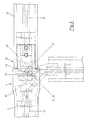
- Fig. 2 einen vergrößerten Ausschnitt mit einer gelenkigen Rahmenverbindung und
- Fig. 3 den vergrößerten Ausschnitt der Fig. 2 in Draufsicht bei ausgestreckter und abgewinkelter Lage der Rahmenverbindung.
- Ein Maschinenrahmen (1) stützt sich mit zwei Laufrädern (2) auf den Erdboden ab. Der Maschinenrahmen (1) trägt zwei Arbeitswerkzeuge (3, 3′) mit einer senkrechten Achse, die mit nicht dargestellten Getrieben angetrieben werden. Der Maschinenrahmen (1) ist mindestens an einem Ende mit einer in einer Vertikalebene liegenden Gabel (4) versehen. Ein Gabelauge (5) bildet zusammen mit einem Deckel (6) eine Hohlkugel (7). In dieser Hohlkugel (7) ist eine Gelenkkugel (8) drehbar eingelassen. Die Gelenkkugel (8) besitzt eine Mittelbohrung (9). Das andere Gabelauge (10) besitzt einen nach innen gerichteten Stift (15).
- Ein Werkzeugträger (12), der mit dem Maschinenrahmen (1) gelenkig zu verbinden ist, hat mindestens an einem Ende ebenfalls eine Gabel (13′, 13˝). Der Werkzeugträger (12) besitzt ebenfalls ein Laufrad (2) und ein Arbeitswerkzeug (3˝). Die Gabel (13′, 13˝) trägt an ihren Enden einen nach außen gerichteten Stift (14) und einen längsgerichteten Schlitz (11). Der Stift (14) am Gabelauge (13′) besitzt einen Bund (14′) und der Stift (15) am Gabelauge (10) einen Bund (15′). Der Bund (14′) kann sich gegen die Stirnseite der Gelenkkugel (8) anlegen, der Bund (15′) gegen die Innenkanten des Schlitzes (11).
- Der Maschinenrahmen (1) und der Werkzeugträger (12) werden von einer Gelenkwelle (17) durchsetzt (Fig. 1), die ein Weitwinkel- bzw. Doppelkreuzgelenk (17′) einschließen.
- Bei der Arbeit haben der Maschinenrahmen (1) und der Werkzeugträger (12) eine Stellung, wie in den Fig. 1 und 2 gezeigt. Nicht dargestellte Streben verhindern den Werkzeugträger (12) an einer Drehung um die Achse der Stifte (14, 15). Längskräfte im Werkzeugträger (12) in Richtung des Pfeiles A werden von dem Kugelgelenk (7, 8) sicher aufgenommen. Bewegungen zur Bodenanpassung im Sinne des Pfeiles B sind möglich, soweit der Schlitz (11) eine Bewegung am Stift (15) in Richtung des Pfeiles C zuläßt.
- Um den Werkzeugträger (12) in eine Transportstellung zu bringen, wird dieser nach Lösen der nicht gezeichneten Streben um die Achse der Stifte (14, 15) etwa um 90° nach hinten verschwenkt. Der Werkzeugträger (12) bleibt auch in dieser Lage in einem Maße höhenbeweglich, wie der Schlitz (11) eine Bewegung am Stift (15) zuläßt.
- Aus Fig. 3 ist eine vorteilhafte Anordnung der vertikalen Achse (Achse der Stifte 14, 15) der Gelenkverbindung des Maschinenrahmens (1) mit dem Werkzeugträger (12) gezeigt. Die Achse verläuft in etwa der Schnittlinie zweier vertikalen Ebenen (18, 18′), die rechtwinklig und mittig auf einer Verbindungslinie zwischen den Achsen der Kreuzgelenke (16′, 16˝) des Doppelkreuzgelenkes in deren ausgestreckten und deren für eine Transportstellung der Maschine abgewinkelten Lage stehen.
Claims (4)
Priority Applications (1)
| Application Number | Priority Date | Filing Date | Title |
|---|---|---|---|
| AT88116368T ATE77910T1 (de) | 1987-11-21 | 1988-10-04 | Gelenkige rahmenverbindung fuer futtererntemaschinen. |
Applications Claiming Priority (2)
| Application Number | Priority Date | Filing Date | Title |
|---|---|---|---|
| DE19873739485 DE3739485A1 (de) | 1987-11-21 | 1987-11-21 | Gelenkige rahmenverbindung fuer futtererntemaschinen |
| DE3739485 | 1987-11-21 |
Publications (3)
| Publication Number | Publication Date |
|---|---|
| EP0317746A2 true EP0317746A2 (de) | 1989-05-31 |
| EP0317746A3 EP0317746A3 (en) | 1990-06-27 |
| EP0317746B1 EP0317746B1 (de) | 1992-07-08 |
Family
ID=6340963
Family Applications (1)
| Application Number | Title | Priority Date | Filing Date |
|---|---|---|---|
| EP88116368A Expired - Lifetime EP0317746B1 (de) | 1987-11-21 | 1988-10-04 | Gelenkige Rahmenverbindung für Futtererntemaschinen |
Country Status (3)
| Country | Link |
|---|---|
| EP (1) | EP0317746B1 (de) |
| AT (1) | ATE77910T1 (de) |
| DE (2) | DE3739485A1 (de) |
Cited By (7)
| Publication number | Priority date | Publication date | Assignee | Title |
|---|---|---|---|---|
| DE4110634A1 (de) * | 1991-04-02 | 1992-10-08 | Krone Bernhard Gmbh Maschf | Gelenkige rahmenverbindung |
| US5346018A (en) * | 1992-10-26 | 1994-09-13 | Koster Rick L | Vehicle hydraulic three-point hitch and power take-off shaft |
| EP0628240A1 (de) * | 1993-06-07 | 1994-12-14 | Maasland N.V. | Heuwerbungsmaschine |
| EP0763321A1 (de) * | 1995-09-15 | 1997-03-19 | Kuhn S.A. | Heuwerbungsmaschine |
| FR2740653A1 (fr) * | 1995-11-07 | 1997-05-09 | Kuhn Sa | Machine de fenaison, notamment une faneuse, comportant un bati avec des parties laterales repliables |
| EP0779022A1 (de) * | 1995-12-15 | 1997-06-18 | Kuhn S.A. | Heuwerbungsmaschine |
| FR2894636A1 (fr) * | 2005-12-14 | 2007-06-15 | Yves Gersent | Agencement de deux arbres aptes a etre mis en rotation. |
Families Citing this family (2)
| Publication number | Priority date | Publication date | Assignee | Title |
|---|---|---|---|---|
| AT397019B (de) * | 1989-07-10 | 1994-01-25 | Stoll Maschf Gmbh Wilhelm | Heuwerbungsmaschine |
| DE19747310C1 (de) * | 1997-10-27 | 1999-08-26 | Walterscheid Gmbh Gkn | Antriebsvorrichtung für eine Landmaschine, insbesondere Kreiselheuer |
Family Cites Families (7)
| Publication number | Priority date | Publication date | Assignee | Title |
|---|---|---|---|---|
| NL274886A (de) * | 1961-02-17 | |||
| DE1266556B (de) * | 1966-06-24 | 1968-04-18 | Fahr Ag Maschf | Gelenkverbindung zwischen den Abschnitten einer mit Tragrohren versehenen Gelenkwelle |
| DE2414769C3 (de) * | 1974-03-27 | 1979-03-29 | Fella-Werke Gmbh, 8501 Feucht | Vorrichtung zum Mähen von verschiedenartigem Schnittgut |
| NL177070C (nl) * | 1979-08-24 | 1985-08-01 | Lely Nv C Van Der | Hooibouwmachine. |
| DE3151481A1 (de) * | 1981-12-24 | 1983-07-07 | Claas Saulgau GmbH, 7968 Saulgau | Landwirtschaftliche maschine |
| CA1243883A (en) * | 1984-03-23 | 1988-11-01 | Gordon L. Salley | Hitch flexing hinge |
| DE3543264A1 (de) * | 1985-12-06 | 1987-06-11 | Kloeckner Humboldt Deutz Ag | Kreiselzettwender |
-
1987
- 1987-11-21 DE DE19873739485 patent/DE3739485A1/de not_active Withdrawn
-
1988
- 1988-10-04 EP EP88116368A patent/EP0317746B1/de not_active Expired - Lifetime
- 1988-10-04 DE DE8888116368T patent/DE3872669D1/de not_active Expired - Fee Related
- 1988-10-04 AT AT88116368T patent/ATE77910T1/de not_active IP Right Cessation
Cited By (12)
| Publication number | Priority date | Publication date | Assignee | Title |
|---|---|---|---|---|
| DE4110634A1 (de) * | 1991-04-02 | 1992-10-08 | Krone Bernhard Gmbh Maschf | Gelenkige rahmenverbindung |
| US5346018A (en) * | 1992-10-26 | 1994-09-13 | Koster Rick L | Vehicle hydraulic three-point hitch and power take-off shaft |
| EP0628240A1 (de) * | 1993-06-07 | 1994-12-14 | Maasland N.V. | Heuwerbungsmaschine |
| NL9300974A (nl) * | 1993-06-07 | 1995-01-02 | Lely Nv C Van Der | Hooibouwmachine. |
| EP0763321A1 (de) * | 1995-09-15 | 1997-03-19 | Kuhn S.A. | Heuwerbungsmaschine |
| FR2738708A1 (fr) * | 1995-09-15 | 1997-03-21 | Kuhn Sa | Machine de fenaison, notamment une andaineuse de vegetaux coupes,comportant un bati portant deux rotors d'andainage |
| US5743075A (en) * | 1995-09-15 | 1998-04-28 | Kuhn, S.A. | Haymaking machine |
| FR2740653A1 (fr) * | 1995-11-07 | 1997-05-09 | Kuhn Sa | Machine de fenaison, notamment une faneuse, comportant un bati avec des parties laterales repliables |
| EP0772970A1 (de) * | 1995-11-07 | 1997-05-14 | Kuhn S.A. | Heuwerbungsmaschine, insbesondere ein Zett-Wender |
| EP0779022A1 (de) * | 1995-12-15 | 1997-06-18 | Kuhn S.A. | Heuwerbungsmaschine |
| FR2742304A1 (fr) * | 1995-12-15 | 1997-06-20 | Kuhn Sa | Machine de fenaison, notamment une andaineuse de vegetaux coupes, comportant des rotors d'andainage relies par une poutre |
| FR2894636A1 (fr) * | 2005-12-14 | 2007-06-15 | Yves Gersent | Agencement de deux arbres aptes a etre mis en rotation. |
Also Published As
| Publication number | Publication date |
|---|---|
| DE3739485A1 (de) | 1989-06-01 |
| EP0317746A3 (en) | 1990-06-27 |
| EP0317746B1 (de) | 1992-07-08 |
| ATE77910T1 (de) | 1992-07-15 |
| DE3872669D1 (de) | 1992-08-13 |
Similar Documents
| Publication | Publication Date | Title |
|---|---|---|
| DE3050792C2 (de) | ||
| DE3789755T2 (de) | Mähmaschine. | |
| EP0277343A1 (de) | Mähmaschine | |
| DE69109186T2 (de) | Landwirtschaftliche Maschine versehen mit zwei Elementen, die mittels eines geschützten Gelenkes miteinander verbunden sind. | |
| DE1248355B (de) | Heuwerbungsmaschine | |
| EP0317746B1 (de) | Gelenkige Rahmenverbindung für Futtererntemaschinen | |
| DE3022833A1 (de) | Vorrichtung zum entwurzeln von baumstuempfen | |
| DE2858680C2 (de) | ||
| DE69207478T2 (de) | Schlepperaufhängung für ein landwirtschaftliches Werkzeug, insbesondere einen Scheibenmäher oder einen Zylindermäher | |
| DE4219484B4 (de) | Heuwerbungsmaschine | |
| DE4242995C2 (de) | Kuppelvorrichtung zum Verbinden eines Traktors mit einem Gerät | |
| DE2806960A1 (de) | Landwirtschaftliche maschine | |
| DE3529771C2 (de) | ||
| DE2414769C3 (de) | Vorrichtung zum Mähen von verschiedenartigem Schnittgut | |
| EP0116662A1 (de) | Landmaschine mit einem Mähwerk und einer Konditioniereinrichtung | |
| DE2707559C2 (de) | Heuwerbungsmaschine zum Zetten/Wenden und Schwaden mit vier angetriebenen Kreiseln | |
| DE69604317T2 (de) | Heuwerbungsmaschine | |
| EP0132012A1 (de) | Mähmaschine | |
| EP0069160A1 (de) | Vorrichtung zum Mähen und Aufbereiten von Erntegut | |
| DE3038584C2 (de) | ||
| DE1137595B (de) | Geraeteanbaugestell zum Anbau an Dreipunktgestaengen von Schleppern | |
| EP0069857A1 (de) | Heuwerbungsmaschine zum Zetten und Schwaden von Erntegut | |
| DE3034213A1 (de) | Rotationsmaehwerk | |
| DE19809368C2 (de) | Schwadleger | |
| DE819596C (de) | Erntemaschine fuer Wurzelfruechte |
Legal Events
| Date | Code | Title | Description |
|---|---|---|---|
| PUAI | Public reference made under article 153(3) epc to a published international application that has entered the european phase |
Free format text: ORIGINAL CODE: 0009012 |
|
| AK | Designated contracting states |
Kind code of ref document: A2 Designated state(s): AT BE CH DE FR IT LI NL SE |
|
| 17P | Request for examination filed |
Effective date: 19891116 |
|
| PUAL | Search report despatched |
Free format text: ORIGINAL CODE: 0009013 |
|
| AK | Designated contracting states |
Kind code of ref document: A3 Designated state(s): AT BE CH DE FR IT LI NL SE |
|
| 17Q | First examination report despatched |
Effective date: 19910925 |
|
| ITF | It: translation for a ep patent filed | ||
| GRAA | (expected) grant |
Free format text: ORIGINAL CODE: 0009210 |
|
| AK | Designated contracting states |
Kind code of ref document: B1 Designated state(s): AT BE CH DE FR IT LI NL SE |
|
| REF | Corresponds to: |
Ref document number: 77910 Country of ref document: AT Date of ref document: 19920715 Kind code of ref document: T |
|
| REF | Corresponds to: |
Ref document number: 3872669 Country of ref document: DE Date of ref document: 19920813 |
|
| ET | Fr: translation filed | ||
| PLBE | No opposition filed within time limit |
Free format text: ORIGINAL CODE: 0009261 |
|
| STAA | Information on the status of an ep patent application or granted ep patent |
Free format text: STATUS: NO OPPOSITION FILED WITHIN TIME LIMIT |
|
| 26N | No opposition filed | ||
| EAL | Se: european patent in force in sweden |
Ref document number: 88116368.7 |
|
| PGFP | Annual fee paid to national office [announced via postgrant information from national office to epo] |
Ref country code: SE Payment date: 19971006 Year of fee payment: 10 |
|
| PGFP | Annual fee paid to national office [announced via postgrant information from national office to epo] |
Ref country code: DE Payment date: 19971025 Year of fee payment: 10 |
|
| PGFP | Annual fee paid to national office [announced via postgrant information from national office to epo] |
Ref country code: FR Payment date: 19971027 Year of fee payment: 10 |
|
| PGFP | Annual fee paid to national office [announced via postgrant information from national office to epo] |
Ref country code: AT Payment date: 19971028 Year of fee payment: 10 |
|
| PGFP | Annual fee paid to national office [announced via postgrant information from national office to epo] |
Ref country code: NL Payment date: 19971031 Year of fee payment: 10 |
|
| PGFP | Annual fee paid to national office [announced via postgrant information from national office to epo] |
Ref country code: BE Payment date: 19971205 Year of fee payment: 10 |
|
| PGFP | Annual fee paid to national office [announced via postgrant information from national office to epo] |
Ref country code: CH Payment date: 19971231 Year of fee payment: 10 |
|
| PG25 | Lapsed in a contracting state [announced via postgrant information from national office to epo] |
Ref country code: AT Free format text: LAPSE BECAUSE OF NON-PAYMENT OF DUE FEES Effective date: 19981004 |
|
| PG25 | Lapsed in a contracting state [announced via postgrant information from national office to epo] |
Ref country code: SE Free format text: LAPSE BECAUSE OF NON-PAYMENT OF DUE FEES Effective date: 19981005 |
|
| PG25 | Lapsed in a contracting state [announced via postgrant information from national office to epo] |
Ref country code: LI Free format text: LAPSE BECAUSE OF NON-PAYMENT OF DUE FEES Effective date: 19981031 Ref country code: CH Free format text: LAPSE BECAUSE OF NON-PAYMENT OF DUE FEES Effective date: 19981031 Ref country code: BE Free format text: LAPSE BECAUSE OF NON-PAYMENT OF DUE FEES Effective date: 19981031 |
|
| BERE | Be: lapsed |
Owner name: CLAAS SAULGAU G.M.B.H. Effective date: 19981031 |
|
| PG25 | Lapsed in a contracting state [announced via postgrant information from national office to epo] |
Ref country code: NL Free format text: LAPSE BECAUSE OF NON-PAYMENT OF DUE FEES Effective date: 19990501 |
|
| REG | Reference to a national code |
Ref country code: CH Ref legal event code: PL |
|
| EUG | Se: european patent has lapsed |
Ref document number: 88116368.7 |
|
| PG25 | Lapsed in a contracting state [announced via postgrant information from national office to epo] |
Ref country code: FR Free format text: LAPSE BECAUSE OF NON-PAYMENT OF DUE FEES Effective date: 19990630 |
|
| NLV4 | Nl: lapsed or anulled due to non-payment of the annual fee |
Effective date: 19990501 |
|
| REG | Reference to a national code |
Ref country code: FR Ref legal event code: ST |
|
| PG25 | Lapsed in a contracting state [announced via postgrant information from national office to epo] |
Ref country code: DE Free format text: LAPSE BECAUSE OF NON-PAYMENT OF DUE FEES Effective date: 19990803 |
|
| PG25 | Lapsed in a contracting state [announced via postgrant information from national office to epo] |
Ref country code: IT Free format text: LAPSE BECAUSE OF NON-PAYMENT OF DUE FEES;WARNING: LAPSES OF ITALIAN PATENTS WITH EFFECTIVE DATE BEFORE 2007 MAY HAVE OCCURRED AT ANY TIME BEFORE 2007. THE CORRECT EFFECTIVE DATE MAY BE DIFFERENT FROM THE ONE RECORDED. Effective date: 20051004 |