EP0317771B1 - Wirkungsvolle Rückwäsche des Siebs eines Diffusors/Eindickers - Google Patents
Wirkungsvolle Rückwäsche des Siebs eines Diffusors/Eindickers Download PDFInfo
- Publication number
- EP0317771B1 EP0317771B1 EP88117659A EP88117659A EP0317771B1 EP 0317771 B1 EP0317771 B1 EP 0317771B1 EP 88117659 A EP88117659 A EP 88117659A EP 88117659 A EP88117659 A EP 88117659A EP 0317771 B1 EP0317771 B1 EP 0317771B1
- Authority
- EP
- European Patent Office
- Prior art keywords
- pulp
- vessel
- screens
- liquid
- cylinder
- Prior art date
- Legal status (The legal status is an assumption and is not a legal conclusion. Google has not performed a legal analysis and makes no representation as to the accuracy of the status listed.)
- Expired - Lifetime
Links
- 239000002562 thickening agent Substances 0.000 title description 2
- 239000007788 liquid Substances 0.000 claims abstract description 59
- 230000000694 effects Effects 0.000 claims abstract description 9
- 238000004891 communication Methods 0.000 claims abstract description 6
- 239000012530 fluid Substances 0.000 claims abstract description 5
- 238000000605 extraction Methods 0.000 claims description 17
- 238000000034 method Methods 0.000 claims description 16
- 239000007921 spray Substances 0.000 claims description 4
- 238000012216 screening Methods 0.000 claims description 2
- 229920001131 Pulp (paper) Polymers 0.000 abstract description 3
- 230000032258 transport Effects 0.000 abstract 1
- 238000009792 diffusion process Methods 0.000 description 10
- 238000005406 washing Methods 0.000 description 7
- 238000004061 bleaching Methods 0.000 description 6
- 239000000463 material Substances 0.000 description 6
- 238000006073 displacement reaction Methods 0.000 description 5
- 230000008719 thickening Effects 0.000 description 4
- 238000009434 installation Methods 0.000 description 3
- RTAQQCXQSZGOHL-UHFFFAOYSA-N Titanium Chemical compound [Ti] RTAQQCXQSZGOHL-UHFFFAOYSA-N 0.000 description 2
- 238000004140 cleaning Methods 0.000 description 2
- 229910052719 titanium Inorganic materials 0.000 description 2
- 239000010936 titanium Substances 0.000 description 2
- 239000007844 bleaching agent Substances 0.000 description 1
- 230000007423 decrease Effects 0.000 description 1
- 230000001934 delay Effects 0.000 description 1
- 239000000835 fiber Substances 0.000 description 1
- 230000000977 initiatory effect Effects 0.000 description 1
- 238000007689 inspection Methods 0.000 description 1
- 238000005086 pumping Methods 0.000 description 1
- 238000005096 rolling process Methods 0.000 description 1
- 239000000725 suspension Substances 0.000 description 1
Images

Classifications
-
- D—TEXTILES; PAPER
- D21—PAPER-MAKING; PRODUCTION OF CELLULOSE
- D21F—PAPER-MAKING MACHINES; METHODS OF PRODUCING PAPER THEREON
- D21F1/00—Wet end of machines for making continuous webs of paper
- D21F1/66—Pulp catching, de-watering, or recovering; Re-use of pulp-water
-
- B—PERFORMING OPERATIONS; TRANSPORTING
- B01—PHYSICAL OR CHEMICAL PROCESSES OR APPARATUS IN GENERAL
- B01D—SEPARATION
- B01D33/00—Filters with filtering elements which move during the filtering operation
- B01D33/01—Filters with filtering elements which move during the filtering operation with translationally moving filtering elements, e.g. pistons
- B01D33/03—Filters with filtering elements which move during the filtering operation with translationally moving filtering elements, e.g. pistons with vibrating filter elements
- B01D33/0307—Filters with filtering elements which move during the filtering operation with translationally moving filtering elements, e.g. pistons with vibrating filter elements with bag, cage, hose, tube, sleeve or the like filtering elements
- B01D33/0315—Filters with filtering elements which move during the filtering operation with translationally moving filtering elements, e.g. pistons with vibrating filter elements with bag, cage, hose, tube, sleeve or the like filtering elements arranged for inward flow filtration
-
- D—TEXTILES; PAPER
- D21—PAPER-MAKING; PRODUCTION OF CELLULOSE
- D21C—PRODUCTION OF CELLULOSE BY REMOVING NON-CELLULOSE SUBSTANCES FROM CELLULOSE-CONTAINING MATERIALS; REGENERATION OF PULPING LIQUORS; APPARATUS THEREFOR
- D21C9/00—After-treatment of cellulose pulp, e.g. of wood pulp, or cotton linters ; Treatment of dilute or dewatered pulp or process improvement taking place after obtaining the raw cellulosic material and not provided for elsewhere
- D21C9/02—Washing ; Displacing cooking or pulp-treating liquors contained in the pulp by fluids, e.g. wash water or other pulp-treating agents
- D21C9/04—Washing ; Displacing cooking or pulp-treating liquors contained in the pulp by fluids, e.g. wash water or other pulp-treating agents in diffusers ; Washing of pulp of fluid consistency without substantially thickening
-
- B—PERFORMING OPERATIONS; TRANSPORTING
- B01—PHYSICAL OR CHEMICAL PROCESSES OR APPARATUS IN GENERAL
- B01D—SEPARATION
- B01D33/00—Filters with filtering elements which move during the filtering operation
- B01D33/01—Filters with filtering elements which move during the filtering operation with translationally moving filtering elements, e.g. pistons
- B01D33/03—Filters with filtering elements which move during the filtering operation with translationally moving filtering elements, e.g. pistons with vibrating filter elements
- B01D33/0307—Filters with filtering elements which move during the filtering operation with translationally moving filtering elements, e.g. pistons with vibrating filter elements with bag, cage, hose, tube, sleeve or the like filtering elements
- B01D33/033—Filters with filtering elements which move during the filtering operation with translationally moving filtering elements, e.g. pistons with vibrating filter elements with bag, cage, hose, tube, sleeve or the like filtering elements arranged for outward flow filtration
-
- B—PERFORMING OPERATIONS; TRANSPORTING
- B01—PHYSICAL OR CHEMICAL PROCESSES OR APPARATUS IN GENERAL
- B01D—SEPARATION
- B01D33/00—Filters with filtering elements which move during the filtering operation
- B01D33/35—Filters with filtering elements which move during the filtering operation with multiple filtering elements characterised by their mutual disposition
- B01D33/37—Filters with filtering elements which move during the filtering operation with multiple filtering elements characterised by their mutual disposition in parallel connection
- B01D33/39—Filters with filtering elements which move during the filtering operation with multiple filtering elements characterised by their mutual disposition in parallel connection concentrically or coaxially
-
- B—PERFORMING OPERATIONS; TRANSPORTING
- B01—PHYSICAL OR CHEMICAL PROCESSES OR APPARATUS IN GENERAL
- B01D—SEPARATION
- B01D33/00—Filters with filtering elements which move during the filtering operation
- B01D33/44—Regenerating the filter material in the filter
- B01D33/48—Regenerating the filter material in the filter by flushing, e.g. counter-current air-bumps
-
- B—PERFORMING OPERATIONS; TRANSPORTING
- B01—PHYSICAL OR CHEMICAL PROCESSES OR APPARATUS IN GENERAL
- B01D—SEPARATION
- B01D33/00—Filters with filtering elements which move during the filtering operation
- B01D33/58—Handling the filter cake in the filter for purposes other than for regenerating the filter cake remaining on the filtering element
- B01D33/60—Handling the filter cake in the filter for purposes other than for regenerating the filter cake remaining on the filtering element for washing
-
- B—PERFORMING OPERATIONS; TRANSPORTING
- B01—PHYSICAL OR CHEMICAL PROCESSES OR APPARATUS IN GENERAL
- B01D—SEPARATION
- B01D33/00—Filters with filtering elements which move during the filtering operation
- B01D33/70—Filters with filtering elements which move during the filtering operation having feed or discharge devices
- B01D33/76—Filters with filtering elements which move during the filtering operation having feed or discharge devices for discharging the filter cake, e.g. chutes
- B01D33/763—Filters with filtering elements which move during the filtering operation having feed or discharge devices for discharging the filter cake, e.g. chutes for continuously discharging concentrated liquid
Definitions
- the backflushing liquid is supplied from within the vessel itself, rather than from the exterior of the vessel.
- the backflushing liquid is provided, according to the invention, from a cylinder which is mounted to the bottom of the screen supporting conduit.
- the cylinder has a first open end in communication with the interior of the screen support conduit, and a second open end in open communication with the pulp being treated within the vessel.
- a piston is mounted within the cylinder, and relative movement between the piston and cylinder is effected.
- Utilizing the invention not only is it possible to eliminate the accumulator, piping, and its other associated components as described above, but it is also possible to more efficiently treat a larger capacity of pulp. For example, according to the invention it is possible to increase capacity of pulp being treated by as much as about 15% in the case of diffusion washing, while increasing the efficiency of the diffusion washing by as much as 20 to 30%. Since the entire volume of backflushing liquid is provided from within the vessel itself, surge is eliminated thereby expanding the number of treatment techniques that can be practiced utilizing the invention.
- a method of effecting treatment of pulp with screens while minimizing screen clogging is provided, utilizing a generally upright vessel having a pulp inlet and a pulp outlet, the screens mounted to a supporting conduit within the vessel, and the screens having screening surfaces extending generally vertically.
- the method comprises the steps of: (a) Passing pulp generally vertically in the vessel from the inlet to the outlet. (b) Effecting substantially continuous extraction of liquid from the screens through the screen support conduit at a predetermined flow rate. (c) Effecting generally vertical movement of the screens and support conduit in the direction of pulp flow at a first speed, and in the direction opposite pulp flow at a second speed much higher than the first speed.
- a significant object according to the present invention is to effectively back flush screens in a pulp treatment vessel in a simple manner.
- FIGURE 1 illustrates a conventional diffusion washer which is used for washing paper pulp, and effects backflushing of the screens to keep them unclogged.
- This conventional apparatus indicated generally by reference numeral 10, includes a generally upright vessel 11 having a pulp inlet 12 and a pulp outlet 13 which are vertically spaced from each other. The pulp is introduced into the pulp inlet 12, which typically is at the bottom, and flows vertically within the vessel 11, being discharged through the conduit 13 adjacent the top.
- the basic operative components of the device 10 comprise a plurality of concentric cylindrical screens 14, having screen faces 15 which are generally vertical and are in contact with the pulp.
- the concentric screens 14 are supported on support conduits 16, which typically are in the shape of arms extending radially outwardly from a central hub section 17.
- the conduits 16 are hollow, and the interior may be divided into chambers if desirable.
- the screen arms 16 are mounted for reciprocation in the vertical directions by a reciprocating power structure or structures, preferably three or more hydraulic cylinders 18 which are equally spaced around the periphery of the device 10.
- the cylinders 18 reciprocate the screens 14 and support arms 16 so that they move very slowly in the direction of pulp movement (arrows A in FIGURE 1) until the end of the vertical stroke is reached, and then reverse and move opposite to the direction A. While the relative speeds in direction A and opposite to direction A can be varied, in many installations the movement in direction A is much slower than the movement in the direction opposite to A (i.e. downwardly in the exemplary embodiment illustrated). This serves to assist in keeping the screens 14 relatively clog-free.
- a significant difficulty is that when back flush liquid is being supplied to the vessel 11 from the accumulator 24, a "surge" takes place in the vessel 11 since the interior volume of fluent material increases.
- Another difficulty is associated with the constant switching on and switching off of the on/off valves 21, 23, with resultant time delays, the pulp treatment is not as efficient as desirable, and which capacity is limited.
- most accumulators typically discharge the liquid initially at a high pressure, and then at a lesser pressure as the gas driving the liquid out of the accumulator increases its volume.
- the on/off valves 21, 23, pump 25, and accumulator 24 (which must be made of expensive material such as titanium for some uses, such as displacement bleaching) are very expensive.
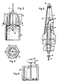
- FIGURES 2 through 5 One exemplary embodiment of the invention is illustrated in FIGURES 2 through 5, with portions of a second embodiment illustrated in FIGURE 6. According to the invention all of the above-mentioned problems associated with the prior art have been eliminated in a simple and effective manner. Utilizing the structures such as illustrated in FIGURES 2 through 5 for diffusion washing, for example, it is possible to increase capacity by as much as about 15%, and to increase washing efficiency by as much as about 20 to 30%, compared to the conventional diffusion washers illustrated in FIGURE 1.
- FIGURES 2 through 5 Component parts of the structure illustrated in FIGURES 2 through 5 that are comparable to those in FIGURE 1 are illustrated by the same reference numeral only preceded by a "1".
- the device 110 is very similar to the device 10, the major difference being the apparatus and manner for backflushing. Rather than periodically terminating extraction through conduit 120, in the device 110 extraction is essentially continuous.
- the control valve (as opposed to an off/off valve) 40 is controlled to regulate the rate at which liquid is being extracted from the pulp, which will depend upon whether or not the pulp is being thickened or diluted or retaining the same consistency, the treatment liquid, etc.
- the source of backflushing liquid is located interiorly of the vessel 111 rather than exteriorly thereof. What this means is that when backflushing occurs there is no surge within the vessel 111 since the volume of fluent material within the vessel 111 remains essentially the same.
- the backflushing apparatus in the preferred embodiment illustrated in FIGURES 2 through 5, comprises a simple cylinder 42 which is open at both ends thereof.
- the first end 43 is open into the interior of the conduit 116, and the second end 44 is open to the volume of pulp within the vessel 111.
- Mounted within the cylinder 42 for relative reciprocation with respect to the cylinder 42 is a piston 46, which is connected to a piston rod 47.
- that piston rod 47 which may be composed of several sections as illustrated by the connector 48 (see FIGURES 2 and 5), is ultimately connected to a small hydraulic cylinder 49 mounted atop the entire device 110.
- the cylinder 49 effects movement of the piston 46 with respect to the cylinder 42.
- the cylinder 42 and piston 46 need not be made of any special materials, and no particular care is necessary to see that there is a tight seal therebetween. Small amounts of leakage between the piston 46 and cylinder 42 are inconsequential. It is only important to make sure that the piston 46 and cylinder 42 are of compatible material so that they do not harm each other.
- FIGURES 3 and 4 illustrate in somewhat more detail than FIGURE 2 one way in which the cylinder 42 can be attached to the hub section of the conduits 116. These exact details of attachment are not particularly significant as far as the invention is concerned, however, it being necessary only to make sure that the connection is secure and that there is a free flow of extraction/backflushing liquid through the hole 50 in the bottom of the hub section of conduits 116, and the open first end 43 of the cylinder 42.
- FIGURE 5 illustrates the details of the top portion of the device 110 and shows how the piston rod 47 passes through stuffing box 52, and through the conventional pipes 53, 54 which supply the treatment fluid to the arms 130.
- FIGURE 6 illustrates an embodiment in which the piston remains stationary.
- structures generally comparable to those in the FIGURES 2 through 5 embodiment are illustrated by the same reference numeral only preceded by a "2".
- the piston 246 is mounted stationary with respect to the vessel 111 since the rod 247 is connected to a support structure 60 at the top of the device 110 in a relatively rigid manner.
- cooperating nuts 61, 62 are shown which engage a threaded end of the piston rod 247 and therefore hold it in place.
- the relative movement between the piston 246 and the cylinder 242 takes place solely as a result of action by the cylinders 118, and the "zero" position of the components is as illustrated in FIGURE 6, with the piston 246 adjacent the bottom, or second open end 244, of the cylinder 242.
- the pulp flows into inlet 112 and upwardly in direction A in vessel 111, ultimately being discharged through discharge 113.
- Treatment liquid such as wash liquid or bleach liquid, is continuously added to the pulp via the rotating arms 130 and the vertical spray tubes 131 depending therefrom. Liquid is withdrawn from the pulp through the screens 114, into the support conduits 116, passing out the conduit 120 through the control valve 40.
- the cylinders 118 move the support conduits 116 and the screens 114 slowly upwardly in the direction of pulp movement until the end of the stroke is reached, and then move them quickly downwardly at the end of the upward stroke, to the bottommost position.
- the cylinder 49 is actuated to quickly move the piston 46 upwardly with respect to the cylinder 42.
- the exact speed of movement is not particularly critical, typically the system would be designed so that it took about two seconds for the piston 46 to move from its lowermost position (in which the volume within the cylinder 42 was filled with a maximum amount of backflushing/extraction liquid from the conduits 116 and with a minimum amount of pulp), to a more upward position (in which the cylinder 42 was filled with a minimum amount of back flush/extraction liquid and a maximum amount of pulp).
- the system is preferably designed so that the effective volume of the cylinder 42 (that is the amount of back flush/extraction liquid that it will contain at the start of the backflushing operation) is enough to effect efficient backflushing. Extraction continues during backflushing.
- the effective volume of the cylinder 42 will be between about 10,000-12,000 liters, or roughly twice the amount of liquid extracted in a minute.
- the cylinder 49 slowly moves the piston 46 downwardly. As it does this, liquid from conduits 116 passes into the cylinder 42 above the piston rod 46. This generally displaces the pulp from behind the piston 46, as the piston 46 moves slowly downwardly in the cylinder 42, and the cylinder 42 fills with liquid from conduits 116.
- FIGURE 6 embodiment is also effective in backflushing the screens, it may be considered to be slightly less effective than the embodiment of FIGURES 2 through 5 since the backflushing action will not start until there has been downward movement of the entire conduit/screen assembly 116, 114.
- the length of the cylinder 42, 242 be designed considering the stroke of the cylinders 118, and whether or not there will be an additional, separate stroke of the piston rod (the FIGURES 2 through 5 embodiment).
- the "backflushing" components used in the method can be considered to be a liquid pumping means in general, located within the vessel and including a chamber defining element (cylinder) and liquid engaging element (piston). While a piston and cylinder are the simplest and therefore the preferred form of such components, other equivalent fluid components, such as a rolling diaphragm in a cylinder, etc., can be utilized where specific requirements call for it.
Landscapes
- Life Sciences & Earth Sciences (AREA)
- Engineering & Computer Science (AREA)
- Wood Science & Technology (AREA)
- Chemical & Material Sciences (AREA)
- Chemical Kinetics & Catalysis (AREA)
- Paper (AREA)
- Photoreceptors In Electrophotography (AREA)
- Filtration Of Liquid (AREA)
- Manipulator (AREA)
- Extrusion Moulding Of Plastics Or The Like (AREA)
- Battery Electrode And Active Subsutance (AREA)
- Pharmaceuticals Containing Other Organic And Inorganic Compounds (AREA)
- Superconductors And Manufacturing Methods Therefor (AREA)
- Networks Using Active Elements (AREA)
- Separation Of Suspended Particles By Flocculating Agents (AREA)
- Nitrogen And Oxygen Or Sulfur-Condensed Heterocyclic Ring Systems (AREA)
- Centrifugal Separators (AREA)
- Disintegrating Or Milling (AREA)
- Polysaccharides And Polysaccharide Derivatives (AREA)
- Bidet-Like Cleaning Device And Other Flush Toilet Accessories (AREA)
- Nitrogen Condensed Heterocyclic Rings (AREA)
- Cyclones (AREA)
- Aeration Devices For Treatment Of Activated Polluted Sludge (AREA)
- External Artificial Organs (AREA)
- Prostheses (AREA)
- Diaphragms For Electromechanical Transducers (AREA)
- Glass Compositions (AREA)
- Preparation Of Clay, And Manufacture Of Mixtures Containing Clay Or Cement (AREA)
Claims (8)
- Zellstoff-Behandlungsanlage mit einem ein Innenvolumen zur Aufnahme von zu behandelndem Zellstoff abgrenzenden, im allgemeinen aufrechten Behälter (111); mit einem Zellstoff-Einlaß (112) zum Behälter (111); mit einem Zellstoff-Auslaß (113) aus dem Behälter (111), wobei der Zellstoff im allgemeinen vertikal zwischen dem Einlaß (112) und dem Auslaß (113) strömt; mit mehreren in dem Behälter (111) montierten und mit tragenden Flüssigkeitsleitungen (116) verbundenen Sieben (114); mit einer Extraktionsvorrichtung zum Abführen von Flüssigkeit aus dem Zellstoff durch die Siebe (114) und durch die Leitungen (116) zu einem Punkt außerhalb des Behälters (111) und mit einer Sieb-Rückspülvorrichtung, dadurch gekennzeichnet,
daß die Sieb-Rückspülvorrichtung innerhalb des Behälters (111) montiert ist und einen Zylinder (42;242) mit offenen Enden (43,44;243,244) enthält, dessen erstes Ende (43;243) in offener Verbindung mit der Flüssigkeit in den Flüssigkeitsleitungen steht und dessen zweites offenes Ende (44;244) in offener Verbindung mit dem Zellstoff in dem Innenvolumen des Behälters (111) steht; daß im Zylinder (42;242) ein Kolben (46;246) für eine relative hin und her gehende Bewegung zwischen dem Kolben (46;246) und dem Zylinder (42;242) montiert ist; und daß eine Vorrichtung zur Bewirkung einer relativen Bewegung zwischen dem Zylinder (42;242) und dem Kolben (46;246) vorgesehen ist, um den Kolben (46;246) zu veranlassen, in einer Richtung der relativen Bewegung zwischen Zylinder (42;242) und Kolben (46;246) Flüssigkeit aus dem Zylinder (42; 242) zu drängen, um eine Rückspülung zu bewirken, und in der anderen Richtung der relativen Bewegung zwischen Zylinder (42;242) und Kolben (46;246) Flüssigkeit in den Zylinder aufzunehmen, wobei die Vorrichtung zur Bewirkung der relativen Bewegung zwischen Zylinder (42;242) und Kolben (46;246) eine Kolbenstange enthält. - Anlage nach Anspruch 1, gekennzeichnet durch eine Vorrichtung (118) zur Bewirkung einer vertikalen Bewegung der Siebe (114) und der tragenden Flüssigkeitsleitungen (116) in der Richtung der Zellstoffbewegung mit einer ersten Geschwindigkeit und in der zur Zellstoffbewegung entgegengesetzten Richtung mit einer zweiten, wesentlich schnelleren Bewegung als die erste Bewegung.
- Anlage nach Anspruch 2, dadurch gekennzeichnet
daß die Vorrichtung zur Bewirkung einer relativen Bewegung zwischen dem Kolben (246) und dem Zylinder (242) im wesentlichen aus der Vorrichtung (118) zur Bewirkung einer vertikalen Bewegung der Siebe (114) und der tragenden Leitungen (116), der Kolbenstange (247) und einer Vorrichtung (60,61 62) zur stationären Halterung der Kolbenstange (247) in Bezug auf den Behälter (111) besteht. - Anlage nach Anspruch 1, gekennzeichnet durch Sprührohre (131) zur Einführung von Behandlungsflüssigkeit zwischen die Siebe (114).
- Verfahren zur Behandlung von Zellstoff mit Sieben (114), während die Siebverstopfung auf einem Kleinstmaß gehalten wird, unter Verwendung eines allgemein aufrechten Behälters (111) mit einem Zellstoff-Einlaß (112) und einem Zellstoff-Auslaß (113), wobei die Siebe (114) auf einer tragenden Leitung (116) innerhalb des Behälters (111) montiert sind und die Siebe (114) Siebflächen besitzen, die sich allgemein in vertikaler Richtung erstrecken, wobei das Verfahren folgende Schritte umfaßt.(a) hindurchlassen von Zellstoff in allgemein vertikaler Richtung im Behälter (111) vom Einlaß (112) zum Auslaß (113);(b) durchführen einer im wesentlichen kontinuierlichen Extraktion von Flüssigkeit von den Sieben (114) durch die Sieb-Tragleitung (116) bei einer vorbestimmten Strömungsgeschwindigkeit; und(c) durchführen einer allgemein vertikalen Bewegung der Siebe (114) und der Tragleitung (116) in Richtung der Zellstoffströmung mit einer ersten Geschwindigkeit und in Richtung entgegengesetzt zur Zellstoffströmung mit einer zweiten Geschwindigkeit, die viel höher ist als die erste Geschwindigkeit, gekennzeichnet durch(d) Zusetzen einer bekannten Flüssigkeitsmenge zur Leitung (116) und zu den Sieben (114) aus dem Behälter (111) bei Bewegung der Siebe (114) in entgegengesetzter Richtung zum Zellstoffstrom, um eine Rückspülung der Siebe (114) ohne eine Druckwelle im Behältervolumen zu bewirken; und(e) Steuerung der kontinuierlichen Extraktions-Strömungsgeschwindigkeit im Hinblick auf die bekannte Menge an Rückspülflüssigkeit, so daß die bekannte Menge an Rückspülflüssigkeit ausreicht, um die Siebe (114) wirksam rückzuspülen und damit deren Verstopfung zu verhindern.
- Verfahren nach Anspruch 5, dadurch gekennzeichnet,
daß der Schritt (e) durch Steuerung der Extraktionsflüssigkeitsströmung derart durchgeführt wird, daß diese Geschwindigkeit in Litern pro Minute annähernd der Hälfte der bekannten Menge an Rückspülflüssigkeit in Litern entspricht. - Verfahren nach Anspruch 5, dadurch gekennzeichnet,
daß der Schritt der Zuführung einer bekannten Flüssigkeitsmenge zur Bewirkung einer Rückspülung der Siebe (114) eingeleitet wird, während die Siebe (114) und die Leitung (116) sich noch in Richtung der Zellstoffströmung bewegen, und zwar gerade vor deren Bewegung entgegen der Richtung der Zellstofströmung. - Verfahren nach Anspruch 5, gekennzeichnet durch
den weiteren Schritt der Einführung von Behandlungsflüssigkeit in den Behälter (111) zwischen den Sieben (114) , um so den Zellstoff mit der Behandlungsflüssigkeit zu behandeln.
Priority Applications (1)
| Application Number | Priority Date | Filing Date | Title |
|---|---|---|---|
| AT88117659T ATE91517T1 (de) | 1987-11-27 | 1988-10-24 | Wirkungsvolle rueckwaesche des siebs eines diffusors/eindickers. |
Applications Claiming Priority (2)
| Application Number | Priority Date | Filing Date | Title |
|---|---|---|---|
| US07/125,710 US4793161A (en) | 1987-11-27 | 1987-11-27 | Effective diffuser/thickener screen backflushing |
| US125710 | 1987-11-27 |
Publications (2)
| Publication Number | Publication Date |
|---|---|
| EP0317771A1 EP0317771A1 (de) | 1989-05-31 |
| EP0317771B1 true EP0317771B1 (de) | 1993-07-14 |
Family
ID=22421038
Family Applications (2)
| Application Number | Title | Priority Date | Filing Date |
|---|---|---|---|
| EP88117659A Expired - Lifetime EP0317771B1 (de) | 1987-11-27 | 1988-10-24 | Wirkungsvolle Rückwäsche des Siebs eines Diffusors/Eindickers |
| EP89107565A Expired - Lifetime EP0343393B1 (de) | 1987-11-27 | 1989-04-26 | Druckverteiler mit mehreren Sieben |
Family Applications After (1)
| Application Number | Title | Priority Date | Filing Date |
|---|---|---|---|
| EP89107565A Expired - Lifetime EP0343393B1 (de) | 1987-11-27 | 1989-04-26 | Druckverteiler mit mehreren Sieben |
Country Status (9)
| Country | Link |
|---|---|
| US (2) | US4793161A (de) |
| EP (2) | EP0317771B1 (de) |
| JP (2) | JP2683259B2 (de) |
| AT (2) | ATE91517T1 (de) |
| BR (2) | BR8806004A (de) |
| CA (2) | CA1330543C (de) |
| DE (2) | DE3882338T2 (de) |
| FI (2) | FI91544C (de) |
| NO (2) | NO174592C (de) |
Families Citing this family (23)
| Publication number | Priority date | Publication date | Assignee | Title |
|---|---|---|---|---|
| US4944167A (en) * | 1987-11-27 | 1990-07-31 | Kamyr Ab | Backflushing pressure diffuser screens |
| US4793161A (en) * | 1987-11-27 | 1988-12-27 | Kamyr Ab | Effective diffuser/thickener screen backflushing |
| US4908896A (en) * | 1987-11-27 | 1990-03-20 | Kamyr Ab | Backflushing pressure diffuser screens |
| SE462435B (sv) * | 1988-11-11 | 1990-06-25 | Kamyr Ab | Saett att stabilisera tryck- och floedesfoerhaallandena i en silapparat och silapparat haerfoer |
| US4975148A (en) * | 1988-12-06 | 1990-12-04 | Ahlstromforetagen Svenska Ab | Cold blow system for batch production of pulp |
| US4971694A (en) * | 1989-01-05 | 1990-11-20 | Kamyr Ab | Double diffuser with backflush pistons |
| US5114536A (en) * | 1989-05-15 | 1992-05-19 | Kangas Martti Y O | Method for cleaning fibers |
| US5027620A (en) * | 1990-02-26 | 1991-07-02 | Kamyr Ab | Diffuser with flexible bellows and internal actuator |
| US5203045A (en) * | 1991-10-15 | 1993-04-20 | Kamyr, Inc. | Nozzle mounting in atmospheric diffusers |
| SE469079B (sv) * | 1992-03-17 | 1993-05-10 | Kamyr Ab | Silanordning med backspolningsorgan |
| SE469387B (sv) * | 1992-05-11 | 1993-06-28 | Kamyr Ab | Saett vid blekning av massa utan anvaendning av klorkemikalier |
| US5312544A (en) * | 1992-10-23 | 1994-05-17 | S. P. Kinney Engineers, Inc. | Continuous strainer |
| EP0615952B1 (de) * | 1993-03-16 | 1999-07-28 | Ykk Corporation | Verfahren zur Herstellung von ultrafeinen Kompositpartikeln aus Aluminiumnitrid und Seltenerdnitrid |
| SE502064C2 (sv) * | 1993-11-29 | 1995-07-31 | Kvaerner Pulping Tech | Sätt och anordning för utmatning av fibermassa |
| EP0796368A1 (de) * | 1994-03-07 | 1997-09-24 | Toivo Aremaa | Verfahren und vorrichtung zur behandlung von einem festen, fliessfähigen oder gasförmigen material, oder dessen kombinationen, insbesondere zellstoff auf einer sieb- oder filterfläche |
| US6272710B1 (en) | 1998-05-07 | 2001-08-14 | James R. Prough | Plate diffuser for treating comminuted cellulosic fibrous material |
| US6706189B2 (en) * | 1998-10-09 | 2004-03-16 | Zenon Environmental Inc. | Cyclic aeration system for submerged membrane modules |
| SE520622C2 (sv) * | 2002-01-25 | 2003-08-05 | Btg Kaelle Inventing Ab | Förfarande och anordning för mätning av koncentrationer |
| US8888958B2 (en) * | 2012-12-31 | 2014-11-18 | Andritz Inc. | Pressure diffuser with an annular baffle screen plate over water inlet |
| WO2017058711A1 (en) * | 2015-09-28 | 2017-04-06 | Converter Manufacturing, Inc. | Apparatus for facilitating peeling of lined containers |
| CN107254837B (zh) * | 2017-01-11 | 2019-03-01 | 宿州市鑫尧健康科技有限公司 | 一种桥梁过滤装置 |
| WO2018153301A1 (zh) * | 2017-02-21 | 2018-08-30 | 中国石油化工股份有限公司 | 改性y型分子筛、其制备方法及包含它的催化剂 |
| JP7163298B2 (ja) * | 2017-02-21 | 2022-10-31 | 中国石油化工股▲ふん▼有限公司 | マグネシウム改質y型分子篩、その生成方法、およびそれを含む触媒 |
Family Cites Families (17)
| Publication number | Priority date | Publication date | Assignee | Title |
|---|---|---|---|---|
| US1601091A (en) * | 1925-10-12 | 1926-09-28 | Wayland Benjamin Bryan | Washing machine |
| US1605412A (en) * | 1926-02-16 | 1926-11-02 | Brodie M Williams | Washing machine |
| US1857026A (en) * | 1929-05-02 | 1932-05-03 | Robert A Ligon | Booster pump for windmills |
| SE306876B (de) * | 1967-05-05 | 1968-12-09 | Kamyr Ab | |
| FR1501962A (fr) * | 1966-09-30 | 1967-11-18 | Filtre à décolmatage automatique et son dispositif de récupération et d'évacuation des boues | |
| NO125495B (de) * | 1966-10-27 | 1972-09-18 | Kamyr Ab | |
| SE324950C (sv) * | 1967-04-13 | 1977-02-28 | Sunds Ab | Forfarande och anordning for vetskebehandling foretredesvis tvettning av fibersuspensioner av cellulosamassa |
| SE342270B (de) * | 1971-02-02 | 1972-01-31 | Kamyr Ab | |
| SE394821B (sv) * | 1975-04-15 | 1977-07-11 | Kamyr Ab | Sett och anordning for avvattning av suspensioner i rorelse |
| US4172037A (en) * | 1975-10-10 | 1979-10-23 | Kamyr Inc. | Continuous process diffuser |
| US4529482A (en) * | 1979-04-25 | 1985-07-16 | Kamyr Aktiebolag | Apparatus for the treatment of pulp having oscillating distributing wiper blades |
| SE435400B (sv) * | 1980-01-10 | 1984-09-24 | Kamyr Ab | Silanordning for avdrag av vetska fran suspensioner i rorelse |
| US4556494A (en) * | 1980-12-04 | 1985-12-03 | Kamyr Aktiebolag | Method of diffusion washing or thickening of pulp |
| DE3173030D1 (en) * | 1980-12-31 | 1986-01-02 | Kamyr, Ab | A method of controlling a pressure-tight vessel for treating cellulosic pulp |
| US4468319A (en) * | 1982-05-04 | 1984-08-28 | Laakso Oliver A | Stationary diffuser |
| GB2159725B (en) * | 1984-06-09 | 1988-06-02 | Klimatank Holdings Limited | Filter apparatus |
| US4793161A (en) * | 1987-11-27 | 1988-12-27 | Kamyr Ab | Effective diffuser/thickener screen backflushing |
-
1987
- 1987-11-27 US US07/125,710 patent/US4793161A/en not_active Expired - Fee Related
-
1988
- 1988-05-18 US US07/195,670 patent/US4840047A/en not_active Expired - Fee Related
- 1988-08-10 CA CA000574302A patent/CA1330543C/en not_active Expired - Fee Related
- 1988-08-10 CA CA000574303A patent/CA1317552C/en not_active Expired - Fee Related
- 1988-09-27 NO NO884268A patent/NO174592C/no unknown
- 1988-10-24 EP EP88117659A patent/EP0317771B1/de not_active Expired - Lifetime
- 1988-10-24 DE DE88117659T patent/DE3882338T2/de not_active Expired - Fee Related
- 1988-10-24 AT AT88117659T patent/ATE91517T1/de not_active IP Right Cessation
- 1988-11-01 FI FI885015A patent/FI91544C/fi not_active IP Right Cessation
- 1988-11-17 BR BR888806004A patent/BR8806004A/pt not_active Application Discontinuation
- 1988-11-22 JP JP63295859A patent/JP2683259B2/ja not_active Expired - Lifetime
-
1989
- 1989-04-12 NO NO89891506A patent/NO891506L/no unknown
- 1989-04-24 FI FI891938A patent/FI891938A7/fi not_active Application Discontinuation
- 1989-04-26 AT AT89107565T patent/ATE93911T1/de not_active IP Right Cessation
- 1989-04-26 DE DE89107565T patent/DE68908771T2/de not_active Expired - Fee Related
- 1989-04-26 EP EP89107565A patent/EP0343393B1/de not_active Expired - Lifetime
- 1989-05-02 JP JP1113517A patent/JPH0217910A/ja active Pending
- 1989-05-15 BR BR898902249A patent/BR8902249A/pt not_active Application Discontinuation
Also Published As
| Publication number | Publication date |
|---|---|
| NO891506D0 (no) | 1989-04-12 |
| ATE93911T1 (de) | 1993-09-15 |
| FI891938A0 (fi) | 1989-04-24 |
| BR8806004A (pt) | 1989-08-08 |
| EP0343393B1 (de) | 1993-09-01 |
| EP0343393A2 (de) | 1989-11-29 |
| US4840047A (en) | 1989-06-20 |
| DE68908771D1 (de) | 1993-10-07 |
| CA1317552C (en) | 1993-05-11 |
| NO884268D0 (no) | 1988-09-27 |
| JP2683259B2 (ja) | 1997-11-26 |
| EP0343393A3 (de) | 1991-07-10 |
| FI91544B (fi) | 1994-03-31 |
| JPH01162886A (ja) | 1989-06-27 |
| JPH0217910A (ja) | 1990-01-22 |
| NO884268L (no) | 1989-05-29 |
| NO174592B (no) | 1994-02-21 |
| FI885015A0 (fi) | 1988-11-01 |
| DE68908771T2 (de) | 1994-03-17 |
| DE3882338D1 (de) | 1993-08-19 |
| CA1330543C (en) | 1994-07-05 |
| FI885015L (fi) | 1989-05-28 |
| EP0317771A1 (de) | 1989-05-31 |
| BR8902249A (pt) | 1990-01-09 |
| US4793161A (en) | 1988-12-27 |
| FI91544C (fi) | 1994-07-11 |
| NO174592C (no) | 1994-06-01 |
| ATE91517T1 (de) | 1993-07-15 |
| DE3882338T2 (de) | 1993-12-16 |
| NO891506L (no) | 1989-11-20 |
| FI891938A7 (fi) | 1989-11-19 |
Similar Documents
| Publication | Publication Date | Title |
|---|---|---|
| EP0317771B1 (de) | Wirkungsvolle Rückwäsche des Siebs eines Diffusors/Eindickers | |
| US4881286A (en) | Effective diffuser/thickener screen backflushing | |
| FI76130B (fi) | Anordning foer behandling av en suspension med en behandlingsvaetska. | |
| US4971694A (en) | Double diffuser with backflush pistons | |
| EP0356415B1 (de) | Drucksiebdiffusionsanlage mit Zurückströmung | |
| FI94366C (fi) | Menettely paine- ja virtausolosuhteiden tasapainottamiseksi sihtilaitteessa ja sihtilaite tätä varten | |
| US4944167A (en) | Backflushing pressure diffuser screens | |
| US4529482A (en) | Apparatus for the treatment of pulp having oscillating distributing wiper blades | |
| EP0300251B1 (de) | Verfahren und Vorrichtung zum Pumpen hochviskoser Pulpe | |
| EP0444985B1 (de) | Zweifacher Diffusor mit elastischem Balg und innerer pneumatischer Steuerung | |
| US4375410A (en) | Reciprocating diffuser arrangements in an elongated vessel | |
| EP0056859B1 (de) | Anordnungen eines Diffusors | |
| JP4707293B2 (ja) | リグノセルロース含有材料から成るパルプの酸素脱リグニン用システム | |
| US5187956A (en) | Preventing clogging in pressure diffusers | |
| US5250198A (en) | Method for separating solid particles from a liquid | |
| CA1308290C (en) | Backflushing pressure diffuser screens | |
| SU1594235A1 (ru) | Установка дл непрерывного экстрагировани жидкости из волокнистой суспензии | |
| US4564144A (en) | Stationary diffuser | |
| SE444469B (sv) | Anordning for synkroniserad hydraulfluidumforsorjning av tva eller flera hydraulmotorer |
Legal Events
| Date | Code | Title | Description |
|---|---|---|---|
| PUAI | Public reference made under article 153(3) epc to a published international application that has entered the european phase |
Free format text: ORIGINAL CODE: 0009012 |
|
| AK | Designated contracting states |
Kind code of ref document: A1 Designated state(s): AT DE FR SE |
|
| 17P | Request for examination filed |
Effective date: 19891107 |
|
| 17Q | First examination report despatched |
Effective date: 19920121 |
|
| GRAA | (expected) grant |
Free format text: ORIGINAL CODE: 0009210 |
|
| AK | Designated contracting states |
Kind code of ref document: B1 Designated state(s): AT DE FR SE |
|
| REF | Corresponds to: |
Ref document number: 91517 Country of ref document: AT Date of ref document: 19930715 Kind code of ref document: T |
|
| REF | Corresponds to: |
Ref document number: 3882338 Country of ref document: DE Date of ref document: 19930819 |
|
| ET | Fr: translation filed | ||
| PLBE | No opposition filed within time limit |
Free format text: ORIGINAL CODE: 0009261 |
|
| STAA | Information on the status of an ep patent application or granted ep patent |
Free format text: STATUS: NO OPPOSITION FILED WITHIN TIME LIMIT |
|
| 26N | No opposition filed | ||
| EAL | Se: european patent in force in sweden |
Ref document number: 88117659.8 |
|
| PGFP | Annual fee paid to national office [announced via postgrant information from national office to epo] |
Ref country code: FR Payment date: 19950927 Year of fee payment: 8 |
|
| PGFP | Annual fee paid to national office [announced via postgrant information from national office to epo] |
Ref country code: DE Payment date: 19951002 Year of fee payment: 8 |
|
| PGFP | Annual fee paid to national office [announced via postgrant information from national office to epo] |
Ref country code: AT Payment date: 19951023 Year of fee payment: 8 |
|
| PGFP | Annual fee paid to national office [announced via postgrant information from national office to epo] |
Ref country code: SE Payment date: 19961021 Year of fee payment: 9 |
|
| PG25 | Lapsed in a contracting state [announced via postgrant information from national office to epo] |
Ref country code: AT Effective date: 19961024 |
|
| PG25 | Lapsed in a contracting state [announced via postgrant information from national office to epo] |
Ref country code: FR Effective date: 19970630 |
|
| PG25 | Lapsed in a contracting state [announced via postgrant information from national office to epo] |
Ref country code: DE Effective date: 19970701 |
|
| REG | Reference to a national code |
Ref country code: FR Ref legal event code: ST |
|
| PG25 | Lapsed in a contracting state [announced via postgrant information from national office to epo] |
Ref country code: SE Free format text: LAPSE BECAUSE OF NON-PAYMENT OF DUE FEES Effective date: 19971025 |
|
| EUG | Se: european patent has lapsed |
Ref document number: 88117659.8 |