EP0317902A2 - Haarbehandlungsgerät - Google Patents
Haarbehandlungsgerät Download PDFInfo
- Publication number
- EP0317902A2 EP0317902A2 EP88119159A EP88119159A EP0317902A2 EP 0317902 A2 EP0317902 A2 EP 0317902A2 EP 88119159 A EP88119159 A EP 88119159A EP 88119159 A EP88119159 A EP 88119159A EP 0317902 A2 EP0317902 A2 EP 0317902A2
- Authority
- EP
- European Patent Office
- Prior art keywords
- heater
- hair
- reflector
- promoting apparatus
- hair promoting
- Prior art date
- Legal status (The legal status is an assumption and is not a legal conclusion. Google has not performed a legal analysis and makes no representation as to the accuracy of the status listed.)
- Granted
Links
Images


Classifications
-
- A—HUMAN NECESSITIES
- A45—HAND OR TRAVELLING ARTICLES
- A45D—HAIRDRESSING OR SHAVING EQUIPMENT; EQUIPMENT FOR COSMETICS OR COSMETIC TREATMENTS, e.g. FOR MANICURING OR PEDICURING
- A45D7/00—Processes of waving, straightening or curling hair
-
- A—HUMAN NECESSITIES
- A45—HAND OR TRAVELLING ARTICLES
- A45D—HAIRDRESSING OR SHAVING EQUIPMENT; EQUIPMENT FOR COSMETICS OR COSMETIC TREATMENTS, e.g. FOR MANICURING OR PEDICURING
- A45D20/00—Hair drying devices; Accessories therefor
- A45D20/20—Helmets without hot air supply or other ventilation, e.g. electrically heated
-
- A—HUMAN NECESSITIES
- A45—HAND OR TRAVELLING ARTICLES
- A45D—HAIRDRESSING OR SHAVING EQUIPMENT; EQUIPMENT FOR COSMETICS OR COSMETIC TREATMENTS, e.g. FOR MANICURING OR PEDICURING
- A45D20/00—Hair drying devices; Accessories therefor
- A45D20/04—Hot-air producers
- A45D20/08—Hot-air producers heated electrically
- A45D20/14—Portable drying stands
-
- A—HUMAN NECESSITIES
- A45—HAND OR TRAVELLING ARTICLES
- A45D—HAIRDRESSING OR SHAVING EQUIPMENT; EQUIPMENT FOR COSMETICS OR COSMETIC TREATMENTS, e.g. FOR MANICURING OR PEDICURING
- A45D20/00—Hair drying devices; Accessories therefor
- A45D20/22—Helmets with hot air supply or ventilating means, e.g. electrically heated air current
-
- A—HUMAN NECESSITIES
- A45—HAND OR TRAVELLING ARTICLES
- A45D—HAIRDRESSING OR SHAVING EQUIPMENT; EQUIPMENT FOR COSMETICS OR COSMETIC TREATMENTS, e.g. FOR MANICURING OR PEDICURING
- A45D20/00—Hair drying devices; Accessories therefor
- A45D20/22—Helmets with hot air supply or ventilating means, e.g. electrically heated air current
- A45D20/24—Shape or structure of the helmet body
- A45D2020/245—Shape or structure of the helmet body of open configuration, e.g. with several movable heat sources
Definitions
- the present invention relates to a hair promoting apparatus, and more particularly to a hair promoting apparatus of the infrared-ray type for radiating infrared rays towards the human hair to be treated, so as to heat and dry it for the hair promoting processes such as drying after washing the hair, promotion of dyeing, perming, waving the hair and so on.
- Hither-to-known hair promoting apparatuses of the above infrared-ray radiating type comprise an infrared radiator made of a heating wire such as a nichrome wire heated by an electric current flow being arranged in a tube composed of a silica glass, ceramic or the like, so that when it is heated the above tube radiates infrared rays to the human hair for hair processing treatment.
- a heating wire such as a nichrome wire heated by an electric current flow
- the elongated tube for radiating infrared rays (of all kinds) is of a linear configuration (hereinafter referred to as a heater), and a reflector having an arcuate cross section is arranged on the inner rear surface of the above heater so as to raise effectiveness of the radiation of infrared rays.
- a plurality of infrared-ray radiating tubes are disposed at the top, rear and side portions of the human head, so that the infrared rays may be radiated uniformly on each portion thereof.
- the hair promoting apparatus according to the above conventional type also occupies a vast area in a beauty salon or the like due to the fact that it requires a plurality of infrared-ray radiating tubes for surrounding the whole area of the human hair, which occasionally makes its installation impossible.
- a human head as a whole has nearly a circular configuration
- the uniform distance from the heater to each position of the human head cannot be possibly realized, whereby the radiation of infrared rays towards each position thereof is not uniform in quantity, resulting in that the temperature thereof is not uniform either.
- the present invention has been introduced in order to solve the aforementioned problems involved in the infrared rays radiating hair promoting apparatus according to the prior art.
- the first object of the present invention to equalize the distance between the heater and the human hair so as to provide the uniform radiation of infrared rays towards the whole area thereof by making the heater in a circular configuration, and also to enable the heater to radiate infrared rays on a wide area by making the heater rotate about a rotative member, realizing a compact hair promoting apparatus thereby.
- the present invention relates to a hair promoting apparatus to achieve the above-mentioned objects, and its main purpose is to provide a ring-shaped or semicircular shaped heater for radiating infrared rays, a reflector for supporting the heater and also for reflecting the infrared rays radiated from the heater, a rotating member on which the reflector is arranged and rotatably supported for the pivotal motion thereof, and a drive means for activating the rotating member.
- the reflector with an inner cavity for forming a plurality of air blasting holes therein towards a human hair and at the same time to provide an air blower to blast air thereto
- an air blower may be provided in the main body to blast air towards the reflector.
- the hair promoting apparatus is activated by rotating the rotating member by utilization of the drive means and, then rotating the heater and the reflector about the center of the rotating member as the rotation center thereof, enlarging the infrared-ray radiating area thereby.
- the distance between the heater and a human head is equalized, so that the human head may then be settled in a position where the infrared rays may be radiated uniformly over the entire portion thereof.
- the hair promotion is much more effectively performed if air is blasted toward the hair from the air blasting holes in the reflector while or after infrared rays are radiated.
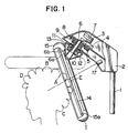
- Fig.1 to Fig.3 show the first embodiment of the present invention.
- 1 denotes a lever for raising or lowering the apparatus in accordance with the height of a human head
- a main body case 2 is fixed at the upper end thereof.
- a motor 3 Inside the main body case 2, a motor 3, a speed reduction gear 4 activated by the motor 3, a transmission main gear 5 engaged with the reduction gear 4, and a gear 7 engaged with the transmission gear 5 and also being loosely fitted to a hollow shaft 6 which is fixed to the main body case 2 are accomodated therein.
- a magnet 8 is fixed, to which a magnet 9 that is loosely fitted to the hollow shaft 6 is also fixed.
- the speed reduction means is not limited to the gear means and it may be a warm-gear reduction or a velt reduction.
- the rotating direction is not limited to only one way either, but can be bidirectional as well.
- the above embodiment shows the case in which a slip clutch is adopted taking advantage of the absorbent force between the magnet 8 and 9, but it may be of a spring tension or of a slip velt
- a rotating tube 6a one end of which is fixed to the magnet 9, is loosely fitted to the hollow shaft 6, and outside the above rotating tube 6a a fixed tube 6b, one end of which is fixed to the main body case 2, is loosely fitted. Furthermore, to the fixed tube 6b the fixed side power feeder 10 is attached, and a rotatable side power feeder 11 is attached to the rotating tube 6a.
- the fixed side power feeder 10 is connected to the main power supply, whereas the rotatable side power feeder 11 is connected to a heater 14 which is explained afterwards, and consequently the heater 14 is connected to the main power supply through both sides of the power feeders 10 and 11.
- a rotating bracket 12 for covering the above both power feeders 10 and 11 is fixed, and to the arm thereof, a reflector 15 for supporting a ring-shaped heater 14 is arranged in such a way that its mounting angle is adjustable.
- the rotatable side power feeder 11 rotates in accordance with the movement of the hollow shaft 6, receiving the electric power supplied to the fixed side power feeder 10 which is connected to the main power supply.
- the heater 14 accomodates an elongated tube made of a silica glass, ceramic or the like with a heating wire 16 stored therein, which is connected to the rotatable side power feeder 11.
- the elongated tube made of a silica glass, ceramic or the like is red heated by conducting the heating wire 16 so as to radiate infrared rays or far infrared rays, and these radiated infrared rays are further reflected by the reflector 15, so that they are concentratedly radiated on the opposite direction thereof.
- the reflecting surface 15a of the reflector 15 is thus arcuatedly formed as shown in Fig. 1 and the heating wire 16 accomodated in the heater 14 comprises a finely wound portion and a roughly wound portion, both of which being supported in such a way that the roughly wound portion is located near the rotating bracket 12, whereas the finely wound portion is located remote therefrom.
- the above-mentioned embodiment regulates that the heater is made of a heating wire with a finely wound portion and a roughly wound portion formed therein so as to differentiate the temperature therebetween, but the heater may be divided into many of small portions thereof so that the hair promotion (drying, perming, etc.) may also be performed by controlling on/off operation of each thereof.
- thermometer 17 is arranged in the surface of the main body case 2 of the heater 14 side for detecting the temperature of the heated object according to the quantity of the infrared rays reflected from the surface thereof
- the heater 14 is conducted to radiate the infrared rays to the hair.
- the range between B and C of the hair is heated when the heater is located in the position illustrated in full lines in Fig. 1, while when located in the position illustrated in dot-dash lines, the range between D and E is heated.
- the range between B and E is constantly heated, whereas the range between D and B, and E and C are irregularly heated depending on the rotation of the heater 14, that is, the temperature in these ranges is always lower than that in the range between B and E.
- the radiation of infrared rays in the range between B and E should be rather weak, while it should become stronger according as the heater comes round to E or to D, and thus the heating wire 16 must be wound partly fine and partly rough as illustrated in Fig.3, so that the uniform rise of temperature can be attained virtually in the whole area of the hair.
- the heater 14 rotatingly radiates the infrared rays, even to the part of the hair where the radiation from the heater 14 does not reach the infrared rays are radiated in accordance with the shifting movement thereof, whereby the radiation of the infrared rays is uniformly applied to the whole area thereof.
- thermometer 17 since the temperature of the hair is detected by a non-contact type thermometer 17, the person whose hair is being treated does not suffer from a possible uncomfortable feeling caused by the fixation of the head, and consequently there will be no local over-heating that may cause a damage to the hair.
- the location shifting movement of a person's head can be sensed by a rise or fall of the temperature, in which state an electric bulbe, buzzer and so on may be provided to notify the person of the movement of the head, whrerby the location thereof may be adjusted.
- the magnets 8 and 9 are slipped off from each other, so that the rotating tube 6a fixed to the magnet 9 stops rotating and consequently the reflector 15 also stops, whereby the accidents such as mulfunction, damage to the wall and so on can be prevented.
- infrared rays can be radiated to a wider range than the widths thereof, whereby the size of the apparatus can be minimized to be more compact than the conventional apparatus.
- the heater 14 may be arranged to stop automatically at the position indicated by the full line (rear part of the human head) as shown in Fig. 1 in the case that the infrared radiation is over or an instruction to stop the rotation thereof is issued.
- the heater 14 and the reflector 15 formed in a ring-shape in the first embodiment are transformed into a semicircular shape, the same function and effects thus can be expected.
- the heater 14 and the reflector 15 may be divided into a plurality of heating apparatuses to form a ring shape by connecting those divided apparatuses.
- the hollow shaft 6 is rotatably supported by the main body case 2, and a fixed air blasting tube 22 connected to an air blower 20 whose one end is arranged inside the main body case 2 is connected to the upper end of the hollow shaft 6 through a rotating seal 21. Accordingly, the fixed air blasting tube 22 cannot possibly be twisted when the hollow shaft rotates.
- the gear 7 and the magnet 8 are loosely attached to the hollow shaft 6, and the magnet 9 is also fixed thereto.
- the gear 7 rotates, the hollow shaft 6 is activated to rotate through the magnet 9 which absorbed by the magnet 8.
- the fixed side power feeder 10 is fixed to the main body case 2, while the rotatable side power feeder 11 is fixed to the hollow shaft 6.
- electric power from the main power supply is transmitted to the heater 14 by way of the fixed side power feeder 10 and the rotatable side power feeder 11.
- a reflector 15 having a reflecting surface 15a forms an inner cavity therebetween, and a plurality of air blasting holes 23 are formed towards the same direction as that of the radiation therefrom.
- the inner cavity of the reflector 15 and the lower end of the hollow shaft 6 are connected to each other by the rotating air blower 24 which passes inside the arm 13.
- a head fixing bar 25 is installed for fixing the position of the human head by contacting the rear portion thereof to the main body case 2, apart from which arrangement nothing is different from the first embodiment.
- the air blower 20 While promoting the human hair by directly and indirectly radiating infrared rays by utilization of the heater 14 and the reflecting surface 15a, it also activates the air blower 20 to rotate simultaneously, so as to send hot or cool air to the inner cavity of the reflector 15 through the rotatably fixed air blasting tube 22, the hollow shaft 6 and the rotatable air blasting tube 24.
- the above blasted air is blown out of the air blasting holes 23, in which case air regardless of cool or hot is blown into the human hair according to the heated level of the infrared rays so as to heat the whole area thereof for the hair promotion.
- the above air blast may be performed when the hair heating is over.
- an air blower 30 directed to the rear portion of the human head is arranged near the lower end of the main body case 2, otherwise, there is no difference between those embodiments shown in Fig.6 and Fig. 7.
- the air from the air blower 30 is blown into the human head when the heater 14 and the reflector 15 rotate about the axis of the hollow shaft 16, and the location thereof is shifted from the front face of the blower 30, accordingly the same effect as the third embodiment is performed in promoting the hair treatment.
- the present invention can also provide a function of a steamer by blowing a spray composed of supersonic waves from the hollow part of the shaft 6 together with the heated infrared radiation from the heater 14.
- infrared rays are radiated simultaneously with eccentrical or reciprocative rotational movement of a heater and a reflector, whereby infrared-ray radiation can be applied to the wider area than the widths of the heater and the reflector themselves.
- the hair promoting apparatus can be compacted so as to be installed in a narrow beauty salon or the like.
- the heater and the reflector are formed in arcuatedly curved shape, so that the distance between the hair promoting apparatus and a human head which is nearly spherical can be uniformly accessed, so that a uniform rise of temperature due to the radiation of infrared rays in the whole area of the hair is made possible and consequently a possible uncomfortable feeling or pain caused by too much partial radiation can be prevented so as to enable a short-time hair promotion.
- the radiation angle varies according to the rotation of a heater, whereby the area where the infrared radiation does not reach by the prior art can be radiated by utilization of the present invention, so that an uniform radiation of infrared rays to the entire area of the hair is enabled.
- the surface portions of the human hair are constantly changed or raised higher than other portions by activating the blower to blast hot or cool air to the hair, whereby the hair promotion can be performed in a better method.
- the hair promotion can be improved regardless of the above heater's radiating direction.
Landscapes
- Cleaning And Drying Hair (AREA)
- Radiation-Therapy Devices (AREA)
Applications Claiming Priority (4)
| Application Number | Priority Date | Filing Date | Title |
|---|---|---|---|
| JP293910/87 | 1987-11-24 | ||
| JP29391087 | 1987-11-24 | ||
| JP63140632A JPH0728770B2 (ja) | 1987-11-24 | 1988-06-09 | 毛髪処理促進装置 |
| JP140632/88 | 1988-06-09 |
Publications (3)
| Publication Number | Publication Date |
|---|---|
| EP0317902A2 true EP0317902A2 (de) | 1989-05-31 |
| EP0317902A3 EP0317902A3 (en) | 1990-06-13 |
| EP0317902B1 EP0317902B1 (de) | 1994-02-02 |
Family
ID=26473088
Family Applications (1)
| Application Number | Title | Priority Date | Filing Date |
|---|---|---|---|
| EP88119159A Expired - Lifetime EP0317902B1 (de) | 1987-11-24 | 1988-11-18 | Haarbehandlungsgerät |
Country Status (5)
| Country | Link |
|---|---|
| US (1) | US4910382A (de) |
| EP (1) | EP0317902B1 (de) |
| JP (1) | JPH0728770B2 (de) |
| KR (1) | KR910008991B1 (de) |
| DE (1) | DE3887646T2 (de) |
Cited By (6)
| Publication number | Priority date | Publication date | Assignee | Title |
|---|---|---|---|---|
| WO1991018534A1 (de) * | 1990-06-07 | 1991-12-12 | Wella Aktiengesellschaft | Behandlungsgerät in offener bauweise für menschliche kopfhaare |
| EP0372443A3 (de) * | 1988-12-06 | 1992-01-22 | OLYMP KARL HERZOG GmbH & Co. | Kopftrockenhaube |
| WO2000064299A1 (en) | 1999-04-22 | 2000-11-02 | Fre.Gis S.R.L. | Hair dryer with swinging arms heat sources |
| EP2020190A1 (de) * | 2007-07-31 | 2009-02-04 | Wella Aktiengesellschaft | Infrarotstrahlungsvorrichtung |
| KR20230007225A (ko) * | 2021-07-05 | 2023-01-12 | 주식회사 맥소드 | 관리 효율성의 향상을 위한 모듈형 모발 처리 장치 |
| US11589661B2 (en) | 2017-01-12 | 2023-02-28 | Dyson Technology Limited | Hand held appliance |
Families Citing this family (34)
| Publication number | Priority date | Publication date | Assignee | Title |
|---|---|---|---|---|
| JPH0618526B2 (ja) * | 1988-09-05 | 1994-03-16 | 株式会社山田電機製作所 | 乾燥アーム群の回転式頭髪乾燥機 |
| JPH07112447B2 (ja) * | 1990-01-24 | 1995-12-06 | タカラベルモント株式会社 | 毛髪処理促進装置 |
| JP2528826Y2 (ja) * | 1991-10-09 | 1997-03-12 | タカラベルモント株式会社 | 毛髪処理促進装置 |
| DE69527671T9 (de) * | 1994-04-27 | 2004-09-09 | Koninklijke Philips Electronics N.V. | Haartrockner mit geregeltem Luftstrom |
| JP3005195U (ja) * | 1994-06-13 | 1994-12-13 | タカラベルモント株式会社 | 毛髪処理促進装置に使用するモータ構造 |
| USD409331S (en) * | 1996-09-25 | 1999-05-04 | Oohiro Works Ltd. | Hair treatment promoting device |
| USD408100S (en) * | 1996-09-25 | 1999-04-13 | Oohiro Works Ltd. | Hair treatment promoting device |
| KR200195568Y1 (ko) * | 1998-06-26 | 2000-09-01 | 김대성 | 할로겐 헤어드라이기 |
| TW355947U (en) * | 1998-09-24 | 1999-04-11 | Yun Yen Co Ltd | Improved structure for hair drier with far infrared ray |
| USD477111S1 (en) | 1999-08-07 | 2003-07-08 | Wella Ag | Hair dryer |
| US6285828B1 (en) | 2000-05-23 | 2001-09-04 | Helen Of Troy | Infrared hair dryer heater |
| USD468483S1 (en) | 2000-08-08 | 2003-01-07 | Oohiro Works, Ltd. | Hair processing accelerator |
| KR100783442B1 (ko) * | 2000-09-08 | 2007-12-07 | 다카라 벨몬트 가부시키가이샤 | 모발처리촉진장치 |
| USD474562S1 (en) | 2000-10-20 | 2003-05-13 | Oohiro Works, Ltd. | Hair processing accelerator |
| JP4456254B2 (ja) * | 2000-10-20 | 2010-04-28 | 株式会社大廣製作所 | 頭髪処理促進機 |
| JP4435398B2 (ja) * | 2000-10-25 | 2010-03-17 | 株式会社大廣製作所 | 頭髪処理促進機 |
| JP4295440B2 (ja) * | 2001-01-09 | 2009-07-15 | 株式会社三龍社 | 同心逆回転減速機を有する頭髪加熱機 |
| US6724984B2 (en) * | 2001-12-05 | 2004-04-20 | Takara Belmont Corporation | Hair treatment promoting apparatus with rotatable reflector |
| US7089718B2 (en) * | 2002-06-10 | 2006-08-15 | Green-Line Products, Inc. | Apparatus for heat-shrinking film onto an open-topped container and method of using same |
| USD527490S1 (en) * | 2003-04-11 | 2006-08-29 | Wella Aktiengesellschaft | Hair dryer |
| WO2005032299A2 (en) * | 2003-09-25 | 2005-04-14 | Rovcal, Inc. | Hair dryers |
| CN100520217C (zh) * | 2004-02-05 | 2009-07-29 | 环球拔萃有限公司 | 放射仪器 |
| EP1863367B1 (de) * | 2005-02-28 | 2008-08-06 | Wella Aktiengesellschaft | Wärmebehandlungsgerät |
| USD622444S1 (en) | 2006-12-05 | 2010-08-24 | Wella Aktiengesellschaft | Hair drying hood |
| USD601750S1 (en) | 2007-10-19 | 2009-10-06 | Wella Aktiengesellschaft | Hair dryer |
| USD628343S1 (en) | 2008-04-17 | 2010-11-30 | Wella Aktiengesellschaft | Infrared radiation dryer |
| US8286645B2 (en) * | 2008-11-26 | 2012-10-16 | Lisa Parberry | Hair iron |
| KR100941869B1 (ko) * | 2009-09-29 | 2010-02-11 | 박향숙 | 헤어 처리장치 |
| KR100979136B1 (ko) * | 2009-11-26 | 2010-09-02 | (주) 에스엠세라믹 | 머리 미용기구 |
| CA141610S (en) * | 2011-05-31 | 2012-02-27 | Takara Belmont Corp | Hair treatment apparatus |
| KR101895613B1 (ko) * | 2011-11-01 | 2018-09-05 | 이승수 | 웨이브퍼머장치 |
| USD671269S1 (en) * | 2012-02-09 | 2012-11-20 | Insynergy Products, Inc. | Hair dryer holder |
| US9408452B1 (en) * | 2015-11-19 | 2016-08-09 | Khaled A. M. A. A. Al-Khulaifi | Robotic hair dryer holder system with tracking |
| US11896104B2 (en) | 2020-08-14 | 2024-02-13 | Conair Llc | Sanitizing hair dryer |
Family Cites Families (17)
| Publication number | Priority date | Publication date | Assignee | Title |
|---|---|---|---|---|
| US1639753A (en) * | 1925-11-28 | 1927-08-23 | William G Shelton | Hair drier and therapeutic lamp |
| FR922103A (fr) * | 1945-12-14 | 1947-05-30 | Séchoir à cheveux | |
| DE867737C (de) * | 1951-10-27 | 1953-02-19 | Kadus Werk Ludwig Kegel K G | Haube zum Trocknen der Haare bzw. zur Haardauerwellung |
| CH466897A (de) * | 1968-06-20 | 1968-12-31 | Roesli Jacques | Gerät zum Trocknen der Haare mittels Warmluft |
| US3646319A (en) * | 1968-12-09 | 1972-02-29 | Merco Products Inc | Infant warmer having electric (infrared) heating means |
| US4191879A (en) * | 1975-09-05 | 1980-03-04 | Kerchner Charles F Jr | Heating apparatus and controls therefor |
| GB1522777A (en) * | 1977-04-27 | 1978-08-31 | Ho Nu Go International Ltd | Hairdryer |
| US4263500A (en) * | 1978-06-19 | 1981-04-21 | Clairol Incorporated | Infrared heating hair dryer |
| US4323761A (en) * | 1979-11-26 | 1982-04-06 | Huebner Otto | Radiant heat hair dryer |
| US4382174A (en) * | 1981-01-09 | 1983-05-03 | Clairol Incorporated | Infra-red hair dryer |
| DE3133851A1 (de) * | 1981-08-27 | 1983-03-24 | Wella Ag | Waermebehandlungsgeraet fuer kopfhaare |
| IT1147960B (it) * | 1982-05-07 | 1986-11-26 | Roberto Giorgis | Dispositivo per asciugare i capelli a sorgenti termiche rotanti |
| US4531047A (en) * | 1982-07-28 | 1985-07-23 | Casso-Solar Corporation | Clip-mounted quartz tube electric heater |
| EP0156984B1 (de) * | 1983-12-16 | 1990-04-25 | TAKARA COMPANY, Inc. | Haarbehandlungsapparat |
| GB8418062D0 (en) * | 1984-07-16 | 1984-08-22 | Atomic Energy Authority Uk | Temperature control |
| IT1208699B (it) * | 1984-10-02 | 1989-07-10 | Giorgis Roberto | Apparecchio asciuga-capelli a lampade ruotanti |
| JPS62181008A (ja) * | 1986-02-04 | 1987-08-08 | 株式会社大廣製作所 | ヘアドライヤ |
-
1988
- 1988-06-09 JP JP63140632A patent/JPH0728770B2/ja not_active Expired - Fee Related
- 1988-11-08 US US07/268,557 patent/US4910382A/en not_active Expired - Lifetime
- 1988-11-18 DE DE3887646T patent/DE3887646T2/de not_active Expired - Lifetime
- 1988-11-18 EP EP88119159A patent/EP0317902B1/de not_active Expired - Lifetime
- 1988-11-24 KR KR1019880015508A patent/KR910008991B1/ko not_active Expired
Cited By (9)
| Publication number | Priority date | Publication date | Assignee | Title |
|---|---|---|---|---|
| EP0372443A3 (de) * | 1988-12-06 | 1992-01-22 | OLYMP KARL HERZOG GmbH & Co. | Kopftrockenhaube |
| WO1991018534A1 (de) * | 1990-06-07 | 1991-12-12 | Wella Aktiengesellschaft | Behandlungsgerät in offener bauweise für menschliche kopfhaare |
| WO2000064299A1 (en) | 1999-04-22 | 2000-11-02 | Fre.Gis S.R.L. | Hair dryer with swinging arms heat sources |
| EP2020190A1 (de) * | 2007-07-31 | 2009-02-04 | Wella Aktiengesellschaft | Infrarotstrahlungsvorrichtung |
| WO2009016598A3 (en) * | 2007-07-31 | 2009-03-26 | Procter & Gamble | Device for the infrared radiation of scalp hair |
| US11589661B2 (en) | 2017-01-12 | 2023-02-28 | Dyson Technology Limited | Hand held appliance |
| US11712098B2 (en) | 2017-01-12 | 2023-08-01 | Dyson Technology Limited | Hand held appliance |
| EP3568038B1 (de) * | 2017-01-12 | 2023-09-06 | Dyson Technology Limited | Tragbare vorrichtung |
| KR20230007225A (ko) * | 2021-07-05 | 2023-01-12 | 주식회사 맥소드 | 관리 효율성의 향상을 위한 모듈형 모발 처리 장치 |
Also Published As
| Publication number | Publication date |
|---|---|
| EP0317902B1 (de) | 1994-02-02 |
| KR910008991B1 (ko) | 1991-10-26 |
| JPH01221104A (ja) | 1989-09-04 |
| DE3887646D1 (de) | 1994-03-17 |
| EP0317902A3 (en) | 1990-06-13 |
| US4910382A (en) | 1990-03-20 |
| DE3887646T2 (de) | 1994-09-15 |
| KR890007695A (ko) | 1989-07-05 |
| JPH0728770B2 (ja) | 1995-04-05 |
Similar Documents
| Publication | Publication Date | Title |
|---|---|---|
| EP0317902A2 (de) | Haarbehandlungsgerät | |
| EP0536443B1 (de) | Ein Haarbehandlungsgerät | |
| EP0156984B1 (de) | Haarbehandlungsapparat | |
| US4259566A (en) | Hair waving applicance having plural independently temperature controllable electric heaters | |
| JPS58501361A (ja) | 人の頭髪を加熱するための熱処理装置 | |
| CA2300594C (en) | Radiant heater for infant warmers | |
| JPH0233684Y2 (de) | ||
| JP2000296017A (ja) | 毛髪処理促進装置 | |
| JPH04129503A (ja) | 毛髪処理促進装置 | |
| JPH04644B2 (de) | ||
| JPH0563404U (ja) | 回転式ヘア・ドライヤ | |
| JP2001345171A (ja) | 高周波加熱装置 | |
| JPH07139744A (ja) | 電気こたつの発熱装置 | |
| JPH0233683Y2 (de) | ||
| JPH02118329A (ja) | 輻射暖房器 | |
| JPH04646B2 (de) | ||
| JPH11128373A (ja) | 赤外線治療器 | |
| JPS62129009A (ja) | 毛髪処理促進制御装置 | |
| JPH04645B2 (de) | ||
| JP3795571B2 (ja) | 赤外線治療器 | |
| KR200256902Y1 (ko) | 헤어 드라이장치 | |
| JPH0667326B2 (ja) | 毛髪処理促進装置 | |
| KR200230123Y1 (ko) | 퍼머기의 헤드 회전장치 | |
| JP2001061977A (ja) | 赤外線治療器 | |
| JP3865286B2 (ja) | 毛髪処理促進装置におけるヒーター取付構造 |
Legal Events
| Date | Code | Title | Description |
|---|---|---|---|
| PUAI | Public reference made under article 153(3) epc to a published international application that has entered the european phase |
Free format text: ORIGINAL CODE: 0009012 |
|
| AK | Designated contracting states |
Kind code of ref document: A2 Designated state(s): DE ES FR GB IT |
|
| PUAL | Search report despatched |
Free format text: ORIGINAL CODE: 0009013 |
|
| AK | Designated contracting states |
Kind code of ref document: A3 Designated state(s): DE ES FR GB IT |
|
| 17P | Request for examination filed |
Effective date: 19900828 |
|
| 17Q | First examination report despatched |
Effective date: 19920305 |
|
| GRAA | (expected) grant |
Free format text: ORIGINAL CODE: 0009210 |
|
| AK | Designated contracting states |
Kind code of ref document: B1 Designated state(s): DE ES FR GB IT |
|
| PG25 | Lapsed in a contracting state [announced via postgrant information from national office to epo] |
Ref country code: FR Effective date: 19940202 Ref country code: ES Free format text: THE PATENT HAS BEEN ANNULLED BY A DECISION OF A NATIONAL AUTHORITY Effective date: 19940202 |
|
| REF | Corresponds to: |
Ref document number: 3887646 Country of ref document: DE Date of ref document: 19940317 |
|
| ITF | It: translation for a ep patent filed | ||
| EN | Fr: translation not filed | ||
| PG25 | Lapsed in a contracting state [announced via postgrant information from national office to epo] |
Ref country code: GB Effective date: 19941118 |
|
| PLBE | No opposition filed within time limit |
Free format text: ORIGINAL CODE: 0009261 |
|
| STAA | Information on the status of an ep patent application or granted ep patent |
Free format text: STATUS: NO OPPOSITION FILED WITHIN TIME LIMIT |
|
| 26N | No opposition filed | ||
| GBPC | Gb: european patent ceased through non-payment of renewal fee |
Effective date: 19941118 |
|
| PGFP | Annual fee paid to national office [announced via postgrant information from national office to epo] |
Ref country code: DE Payment date: 20071130 Year of fee payment: 20 |
|
| PGFP | Annual fee paid to national office [announced via postgrant information from national office to epo] |
Ref country code: IT Payment date: 20071126 Year of fee payment: 20 |