EP0317962A2 - Capteur d'accélération pour système de sécurité des véhicules automobiles - Google Patents
Capteur d'accélération pour système de sécurité des véhicules automobiles Download PDFInfo
- Publication number
- EP0317962A2 EP0317962A2 EP88119431A EP88119431A EP0317962A2 EP 0317962 A2 EP0317962 A2 EP 0317962A2 EP 88119431 A EP88119431 A EP 88119431A EP 88119431 A EP88119431 A EP 88119431A EP 0317962 A2 EP0317962 A2 EP 0317962A2
- Authority
- EP
- European Patent Office
- Prior art keywords
- mass
- acceleration
- acceleration sensor
- sensor according
- accelerations
- Prior art date
- Legal status (The legal status is an assumption and is not a legal conclusion. Google has not performed a legal analysis and makes no representation as to the accuracy of the status listed.)
- Withdrawn
Links
Images

Classifications
-
- G—PHYSICS
- G01—MEASURING; TESTING
- G01P—MEASURING LINEAR OR ANGULAR SPEED, ACCELERATION, DECELERATION, OR SHOCK; INDICATING PRESENCE, ABSENCE, OR DIRECTION, OF MOVEMENT
- G01P15/00—Measuring acceleration; Measuring deceleration; Measuring shock, i.e. sudden change of acceleration
- G01P15/02—Measuring acceleration; Measuring deceleration; Measuring shock, i.e. sudden change of acceleration by making use of inertia forces using solid seismic masses
- G01P15/03—Measuring acceleration; Measuring deceleration; Measuring shock, i.e. sudden change of acceleration by making use of inertia forces using solid seismic masses by using non-electrical means
- G01P15/032—Measuring acceleration; Measuring deceleration; Measuring shock, i.e. sudden change of acceleration by making use of inertia forces using solid seismic masses by using non-electrical means by measuring the displacement of a movable inertial mass
- G01P15/036—Measuring acceleration; Measuring deceleration; Measuring shock, i.e. sudden change of acceleration by making use of inertia forces using solid seismic masses by using non-electrical means by measuring the displacement of a movable inertial mass for indicating predetermined acceleration values
-
- B—PERFORMING OPERATIONS; TRANSPORTING
- B60—VEHICLES IN GENERAL
- B60R—VEHICLES, VEHICLE FITTINGS, OR VEHICLE PARTS, NOT OTHERWISE PROVIDED FOR
- B60R22/00—Safety belts or body harnesses in vehicles
- B60R22/18—Anchoring devices
- B60R22/195—Anchoring devices with means to tension the belt in an emergency, e.g. means of the through-anchor or splitted reel type
- B60R22/1954—Anchoring devices with means to tension the belt in an emergency, e.g. means of the through-anchor or splitted reel type characterised by fluid actuators, e.g. pyrotechnic gas generators
- B60R22/1956—Mechanical triggering means therefor
-
- G—PHYSICS
- G01—MEASURING; TESTING
- G01P—MEASURING LINEAR OR ANGULAR SPEED, ACCELERATION, DECELERATION, OR SHOCK; INDICATING PRESENCE, ABSENCE, OR DIRECTION, OF MOVEMENT
- G01P15/00—Measuring acceleration; Measuring deceleration; Measuring shock, i.e. sudden change of acceleration
- G01P15/02—Measuring acceleration; Measuring deceleration; Measuring shock, i.e. sudden change of acceleration by making use of inertia forces using solid seismic masses
- G01P15/08—Measuring acceleration; Measuring deceleration; Measuring shock, i.e. sudden change of acceleration by making use of inertia forces using solid seismic masses with conversion into electric or magnetic values
- G01P15/0891—Measuring acceleration; Measuring deceleration; Measuring shock, i.e. sudden change of acceleration by making use of inertia forces using solid seismic masses with conversion into electric or magnetic values with indication of predetermined acceleration values
Definitions
- the invention relates to an acceleration sensor for safety systems of motor vehicles, preferably for seat belt systems and so-called buckle, consisting of a displaceably guided sensor mass, which is held in its rest position by holding means and releases a locking device via an actuating device when deflected from its rest position due to the occurrence of predetermined critical acceleration values .
- An acceleration sensor of this type is known, for example, from the applicant's patent application P 37 31 289.8, filed on September 17, 1987.
- Acceleration sensors of this type now act not only on accelerations that are typical of a hazard, such as occur in the event of a crash or accelerations or decelerations caused by an accident, and which are intended to trigger or respond and activate the safety systems, but also accelerations that result from normal driving. For example, driving through potholes causes accelerations of considerable magnitude, but only for a short time. If the acceleration sensor is arranged in a vehicle seat, adjusting the seat and driving it against a stop can also cause accelerations which in themselves are of a magnitude leading to triggering. However, such accelerations occurring during normal vehicle operation are not intended to trigger or activate the Guide safety systems through the acceleration sensors.
- the object of the invention is therefore to provide an acceleration sensor of the type specified at the outset which responds only to accelerations caused by dangers or accidents and not to accelerations which have their cause in normal driving operation.
- this object is achieved in the case of an acceleration sensor of the type specified at the outset in that a device is provided which, in the case of accelerations the size of which reaches or exceeds the critical acceleration values which in themselves lead to triggering, prevents triggering and only causes it when the accelerations have lasted for a minimum time that is typical of accelerations due to danger.
- the invention is based on the knowledge that the response time of conventional sensors becomes shorter as accelerations become larger and is immeasurably short at larger acceleration values.
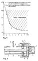
- 1 shows the response range of a conventional sensor in a diagram, the acceleration values being plotted on the ordinate and the response times being plotted on the abscissa.
- the values entered in the diagram have been measured in a test arrangement in which a slide with a sensor arranged on it has been exposed to different delays and the delay values have been determined at which the sensor responds and thereby releases the spring of a lock tensioner. It can be seen from the diagram that the response time at 4.7 g is about 5 ms, but at 5 g it is only about 2 ms. Even at 6.5 g, the response time is immeasurably short.
- driving through potholes can be very high Acceleration values occur which, although they only work for a very short time, trigger the sensor and trigger a hazard.
- accelerations due to their size in the danger zone result in tripping that have lasted for a minimum time, which is typical for accelerations due to danger.
- accelerations caused by normal driving are therefore eliminated as harmless accelerations, which should not lead to tripping, in that they are recognized as harmless due to their short action time.
- the acceleration sensor according to the invention can be designed or set so that it only responds when dangerous accelerations have lasted for at least 2 to 5 ms.
- the device according to the invention can be realized by a mechanical system in that it consists of a displaceably guided first sensor mass, which is coupled on the one hand to a second sensor mass which interacts with the actuating device and on the other hand to a vehicle-fixed part by at least one spring each.
- the first sensor mass is coupled to the vehicle by a spring and the second sensor mass is coupled to the first sensor mass by a spring.
- the acceleration acting on the vehicle is thus transmitted to the first sensor mass via the first spring. Only when the first sensor mass is moved due to the force effect is the second spring tensioned so that it also gives the second sensor mass a movement. This causes a delay in the movement of the second sensor mass, which is provided with the trigger actuation device.
- the second sensor mass is then not moved over the distance required for triggering, if only for a short time accelerations acting at an early stage, the movement of the first sensor mass has ended before it has given the acceleration required for triggering via the second spring to the second sensor mass.
- the spring mass system consisting of two springs and two masses can be designed in such a way that it responds to predetermined accelerations only with a predetermined delay time which corresponds to the desired response time.
- the system according to the invention can thus be matched to the individual vehicle types in accordance with the desired tripping characteristic.
- a constructive solution of a mechanical acceleration sensor according to the invention is the subject of claim 3.
- the acceleration sensor according to the invention can also be implemented by electronic devices.
- an electronic measuring device measuring the path of the mass with a measuring head and an electronic computing device are provided which, in a time below the usual response time, measure the acceleration and the acceleration measurements from the displacement measurements of the accelerated mass and from the time measurements assigned to them from this the path of the mass still belonging to the triggering of the danger is determined and the triggering is initiated when the measuring head has measured this path.
- the acceleration acting in each case is measured and from this measurement the path for the movement of the mass is determined, which indicates that, due to the duration of the action, it is a dangerous acceleration which should lead to a triggering. If the calculated path is reached, it is triggered. If the path is not reached, the signals are deleted and there is no triggering.
- the acceleration is expediently determined from two path measurements and the time between them.
- the measurement is only started when the mass has covered a distance that indicates a dangerous acceleration quantity. In this way, harmless, irrelevant accelerations are eliminated.
- the magnitude of the acceleration is then determined on the basis of the two displacement measurements and is only triggered if this acceleration has lasted for a minimum response time, which results from the calculated displacement length.
- an electronic measuring device measuring the path of the mass with a measuring head and an electronic computing device are provided which, in a time which is below the usual response time, the acceleration from the path measurements of the moving mass and the time measurements assigned to them determined and that acceleration-proportional voltage signals are formed which, depending on the voltage level reached, charge capacitors assigned to these stages, which each initiate tripping if the acceleration continues after a typical charge state of the capacitors.
- a transducer measures the forces exerted on it by the sensor mass and the forces are integrated over time, and that the time integral of the force is compared with a triggering threshold value, when the triggering occurs.
- the time integral can be continuously reduced to zero in accordance with a set time constant of the integration element. This embodiment then does not require a limit determined by a lower acceleration value at which the integration is started.
- a capacitor can be used as an integration element, which is constantly discharged, so that the threshold value is only reached if the capacitor is charged with signals proportional to acceleration over such a long time that the critical triggering threshold value is reached.
- the integration is only started when a force indicating a dangerous acceleration is measured, and that the integration is reduced to zero if the triggering threshold value is not reached.
- the evaluation circuit is therefore only activated when a lower threshold is exceeded. If the triggering threshold value is not reached by the integration, the integration result is deleted so that the described measuring process can be initiated again when accelerations occur again.
- the accelerated sensor mass is decelerated by electromagnetic forces in such a way that acceleration values that are atypical for hazards are eliminated.
- a sensor mass is connected to magnets, preferably permanent magnets, whose magnetic force is applied to a closed pipe or pipe system in a vehicle Circulatory magnetizable liquid acts, which is throttled in this circuit according to the desired damping.
- magnets preferably permanent magnets
- Such magnetic or magnetizable liquids are commercially available and consist of suspensions of very small magnetite or ferrite particles in viscous liquids.
- the magnetizable liquid is magnetically coupled to the magnet or magnets moving with the sensor mass, the desired damping being achieved by correspondingly throttling the magnetizable liquid in the circuit.
- the magnetizable liquid need only be arranged in the area of the magnets, the remaining part of the pipe or the pipe system being filled with a preferably highly viscous separating liquid which does not mix with the magnetizable liquid, so that this separating liquid in the pipe or pipe system from the magnetizable liquid as if displaced by a piston.
- the pipe or the pipe system can also be connected to the sensor mass and the magnet can be arranged fixed to the vehicle.
- a longitudinally displaceably guided sensor mass is expediently connected in the region of its end faces with magnets with flat pole faces that hold armatures that only move in the direction of are displaceable away from the sensor mass, the magnets being enclosed by the pipe system with a closed circuit for the magnetizable liquid which is held in place on the frame.
- the sensor mass consists of a slotted tube with a box profile, on the continuous opposite walls on each end face 3 rectangular permanent magnets are attached at a distance from each other, that the legs of a cross-sectionally H-shaped plastic body engage between the magnets , which is connected to a vehicle-fixed part by a web part which extends the central web and extends through the slot of the tube, that the legs are provided with bores between their end faces and the central web has a bore parallel to these and that the end faces of the plastic body are attached by H -shaped lids are closed, which are provided with connecting channels for connecting respectively opposite bores of the legs and with connecting channels connecting the connecting channels with the bore of the central web, which form throttle sections.
- This configuration achieves particularly effective damping of the sensor mass.
- the hole in the central web is expediently filled with separating liquid.
- the sensor mass can be acted upon by two leaf springs, which are fixed to the end faces of the frame, in the direction of their central position.
- FIG. 1 shows an acceleration time diagram recorded on the basis of a test arrangement with a sensor mounted on a slide, which has already been discussed in the introduction to the description.
- a rod-shaped sensor mass 1 is provided with end-aligned axles 2 which pass through aligned bores 3 of the housing 4.
- Hat-shaped caps 4 which hold the sensor mass 1 in its rest position, are placed on the journal 2 passing through the housing bores 3.
- the journal 2 are guided in the hat-shaped caps 4 with radial play.
- the end faces of the axle journals 2 are against the walls closing the hat-shaped caps.
- Compression springs 8 are clamped between the flange-like edges 6 of the hat-shaped caps 4 and a wall 7 fixed to the housing and hold the flange-shaped edges 9 in contact with the end walls of the housing 4.
- the rod-shaped sensor mass 1 is provided with annular chambers 10 at both ends. These annular chambers 10 have on their inner mutually facing end walls 11 to the sensor mass 1 concentric annular slots 12, in which the ends of a tube piece 13 are guided, which forms a second sensor mass. The ends of the pipe section 13 pass through the annular slots. Rings 14 with a U-shaped cross section are placed on these ends. These rings are supported by springs 15 against the outer walls 16 of the chambers 10. The grooved rings 14 hold the tubular sensor mass 13 in the same way as the hat-shaped caps 4 hold the first sensor mass 1.
- Fig. 2 only the right side of the acceleration sensor is shown, the left side is formed in the same way.
- the tubular second sensor mass 13 is provided in its jacket with a slot 18 into which a sensor 19 engages, which contains a trigger signal when the ends of the slot abut against it.
- the acceleration sensor shown in FIG. 2 consists of a system of two masses 1, 13 coupled together by the spring 15, of which the mass 1 is coupled by the spring 8 to a part 4, 7 fixed to the vehicle.
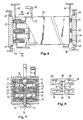
- 3 - 5 are made of spring-mass systems Acceleration sensors are described in which the movements and speeds of the masses caused by accelerations are detected and evaluated by electronic measuring devices.
- a mass 28 is guided in guides 25, 26 of a guide rail 27 and is coupled to a transverse yoke of the rail by a spring 29.
- the rest position of the mass 28 can be secured by a stop.
- a coding 30 consisting of lines is provided, which is detected by the electronic sensor 31. If the mass 28 is moved due to accelerations occurring, the sensor 31 detects the movements of the mass, so that the path length and times and the speeds and accelerations occurring can be determined from the coding.
- the measuring head 31 detects a coding 30 which is arranged on a rod-shaped mass 33 which is sprung at both ends.
- a sector-shaped mass 35 is pivotally mounted about the axis 34 and is coupled to parts fixed to the vehicle by means of two springs 36, 37.
- the mass is provided on an upper peripheral edge with a code 30 which is detected by the measuring head 31. In accordance with accelerations that occur, the mass executes 35 oscillating deflections of various sizes.
- a sensor mass 40 which consists of a tube with a rectangular cross section, which is provided in its lower wall with a longitudinal slot 41.
- the pipe section 40 has in its end regions 3 magnets 42 arranged in pairs, which are fastened opposite one another on the side walls 43, 44 of the pipe section 40.
- the magnets 42 consist of cuboid flat magnets, the opposite broad sides of which form the north and south poles.
- ferromagnetic plates 46, 47 are supported by flange-shaped edges or steps forming part 48, 49 on frame-fixed abutment strips 50, 51 in such a way that the sensor mass the ferromagnetic plates 46, 47 can only move outwards. Due to the magnetic forces, the ferromagnetic plates 46, 47 lead the sensor mass 40 back into their central position via the magnets connected to them if there should be a movement of the sensor mass that did not lead to tripping.
- the legs 53 of a plastic body with an H-shaped cross-section engage, the central web 55 of which is extended in the manner shown in FIG. 7 by a web part 56 which engages through the slot 41 and with a vehicle-fixed one Part is connected.
- the legs of the plastic body 55 are provided with longitudinal rectangular bores or recesses 57 from end to end.
- H-shaped covers 58 are placed on both sides, which close the openings 57.
- the cover 58 is provided with troughs 59 which extend through the openings and are connected to one another by connecting channels 60.
- the connecting channels 60 are connected by throttle channels 61 to a cup-shaped recess 62 which forms the end of a bore 63 which is provided in the central web 55 parallel to the openings 57. While the openings 57 are filled with magnetizable liquid, the bore 63 is with a Release liquid filled.
- the damping mass 40 is acted upon by two leaf springs 65, 66, which are arranged fixed to the vehicle, in the direction of their central position shown in FIG. 6. Furthermore, the sensor mass is provided with a short groove 67 closed at the end, in the central region of which the release lever 68 projects, which is pivotably mounted about an axis 69 fixed to the vehicle.
Landscapes
- Physics & Mathematics (AREA)
- General Physics & Mathematics (AREA)
- Engineering & Computer Science (AREA)
- Mechanical Engineering (AREA)
- Switches Operated By Changes In Physical Conditions (AREA)
- Automotive Seat Belt Assembly (AREA)
- Air Bags (AREA)
Applications Claiming Priority (2)
| Application Number | Priority Date | Filing Date | Title |
|---|---|---|---|
| DE3740353 | 1987-11-27 | ||
| DE3740353 | 1987-11-27 |
Publications (2)
| Publication Number | Publication Date |
|---|---|
| EP0317962A2 true EP0317962A2 (fr) | 1989-05-31 |
| EP0317962A3 EP0317962A3 (fr) | 1990-07-11 |
Family
ID=6341462
Family Applications (1)
| Application Number | Title | Priority Date | Filing Date |
|---|---|---|---|
| EP88119431A Withdrawn EP0317962A3 (fr) | 1987-11-27 | 1988-11-22 | Capteur d'accélération pour système de sécurité des véhicules automobiles |
Country Status (2)
| Country | Link |
|---|---|
| EP (1) | EP0317962A3 (fr) |
| JP (1) | JPH01287469A (fr) |
Cited By (3)
| Publication number | Priority date | Publication date | Assignee | Title |
|---|---|---|---|---|
| DE10324226A1 (de) * | 2002-09-23 | 2004-04-01 | Volkswagen Ag | Betätigungseinrichtung für einen Sperrmechanismus |
| DE19604365B4 (de) * | 1995-02-17 | 2006-04-27 | Volkswagen Ag | Unfalldetektor |
| WO2015032613A3 (fr) * | 2013-09-03 | 2015-04-30 | Bert Grundmann | Capteur d'accélération, en particulier capteur d'accélération duplex, et agencement et procédé de détection d'une perte d'adhérence d'une roue de véhicule |
Family Cites Families (10)
| Publication number | Priority date | Publication date | Assignee | Title |
|---|---|---|---|---|
| US3117196A (en) * | 1960-08-29 | 1964-01-07 | Douglas Aircraft Co Inc | Acceleration operated switch |
| FR1365024A (fr) * | 1963-07-31 | 1964-06-26 | Bendix Corp | Perfectionnements aux accéléromètres |
| US3485973A (en) * | 1967-08-15 | 1969-12-23 | Eaton Yale & Towne | Switch mechanism |
| DE2207831A1 (de) * | 1972-02-19 | 1973-08-23 | Dynamit Nobel Ag | Elektronischer sensor zum ausloesen von sicherheitseinrichtungen beim aufprall von fahrzeugen |
| GB1360661A (en) * | 1972-11-15 | 1974-07-17 | Ferranti Ltd | Accelaration-responsive switching arrangements |
| SE396041B (sv) * | 1976-04-26 | 1977-09-05 | Foerenade Fabriksverken | Fordonsburen anordning for avkenning av huruvida varaktigheten och styrkan av hos fordonet upptredande retardation overstiger forutbestemda verden |
| DE3231800A1 (de) * | 1982-08-26 | 1984-03-01 | Robert Bosch Gmbh, 7000 Stuttgart | Sensor |
| US4679775A (en) * | 1983-09-24 | 1987-07-14 | Yakumo Industrial Corporation | Vibration damping equipment |
| SE460037B (sv) * | 1984-04-13 | 1989-09-04 | Autoliv Dev | Anordning foer styrning av ett laasorgan i en foer fordon avsedd saekerhetssele som har ett utdragbart band, i beroende av utdragningshastighet |
| DE3507738C1 (de) * | 1985-03-05 | 1986-09-04 | Messerschmitt-Bölkow-Blohm GmbH, 8012 Ottobrunn | Linearer Beschleunigungsmesser |
-
1988
- 1988-11-22 EP EP88119431A patent/EP0317962A3/fr not_active Withdrawn
- 1988-11-28 JP JP29844388A patent/JPH01287469A/ja active Pending
Cited By (5)
| Publication number | Priority date | Publication date | Assignee | Title |
|---|---|---|---|---|
| DE19604365B4 (de) * | 1995-02-17 | 2006-04-27 | Volkswagen Ag | Unfalldetektor |
| DE10324226A1 (de) * | 2002-09-23 | 2004-04-01 | Volkswagen Ag | Betätigungseinrichtung für einen Sperrmechanismus |
| WO2015032613A3 (fr) * | 2013-09-03 | 2015-04-30 | Bert Grundmann | Capteur d'accélération, en particulier capteur d'accélération duplex, et agencement et procédé de détection d'une perte d'adhérence d'une roue de véhicule |
| US9989554B2 (en) | 2013-09-03 | 2018-06-05 | Bert Grundmann | Acceleration sensor, especially duplex acceleration sensor, arrangement and method for detecting a loss of adhesion of a vehicle tire |
| US10882499B2 (en) | 2013-09-03 | 2021-01-05 | Bert Grundmann | Acceleration sensor, especially duplex acceleration sensor, arrangement and method for detecting a loss of adhesion of a vehicle tire |
Also Published As
| Publication number | Publication date |
|---|---|
| EP0317962A3 (fr) | 1990-07-11 |
| JPH01287469A (ja) | 1989-11-20 |
Similar Documents
| Publication | Publication Date | Title |
|---|---|---|
| DE2228683C2 (de) | Beschleunigungs- und verzögerungsabhängige, elektrische Schaltvorrichtung zum Einbau in Fahrzeuge | |
| EP0261152B1 (fr) | Dispositif de liberation automatique de dispositifs de protection de passagers dans le cas d'un accident | |
| EP0305765A2 (fr) | Détecteur d'accélération pour systèmes de sécurité et/ou systèmes de ceintures de sécurité de voiture | |
| DE2920147A1 (de) | Anordnung mit einem elektrodynamischen beschleunigungssensor und einer auswerteschaltung | |
| DE3728382A1 (de) | Vorrichtung zum selbsttaetigen ausloesen von insassenschutzvorrichtungen bei einem unfall | |
| DE69218124T2 (de) | Aufprallsensor | |
| EP0689219B1 (fr) | Contacteur mécanique sensible aux mouvements d'un véhicule | |
| DE3049564C2 (fr) | ||
| DE3631651A1 (de) | Aufnahmevorrichtung fuer beschleunigung oder vibration | |
| DE2311014A1 (de) | Sicherheitseinrichtung fuer fahrzeuge | |
| DE3930077A1 (de) | Impulssensor | |
| DE4022388C2 (fr) | ||
| EP0356444A1 (fr) | Commutateur declenche par acceleration | |
| DE3828307A1 (de) | Beschleunigungssensor | |
| DE4443419C1 (de) | Beschleunigungssensor | |
| DE2850836C2 (de) | Elektromagnetischer Geber | |
| DE2803781A1 (de) | Verzoegerungsaufnehmer, insbesondere zur ausloesung von insassen-schutzvorrichtungen im kraftfahrzeug | |
| DE4243101A1 (fr) | ||
| DE3021317A1 (de) | Messeinrichtung fuer ein fahrzeug | |
| DE3804032A1 (de) | Verfahren und vorrichtung zur beschleunigungsmessung | |
| DE4101060A1 (de) | Neigungssensor | |
| DE19731870C1 (de) | Vorrichtung zum Schmieren der Räder von Fahrzeugen, insbesondere zum Schmieren der Spurkränze von Schienenfahrzeugen | |
| DE69102888T2 (de) | Beschleunigungssensor. | |
| DE2926247A1 (de) | Bremswarneinrichtung fuer kraftfahrzeuge | |
| DE10118491C2 (de) | Stoßimpulssensor |
Legal Events
| Date | Code | Title | Description |
|---|---|---|---|
| PUAI | Public reference made under article 153(3) epc to a published international application that has entered the european phase |
Free format text: ORIGINAL CODE: 0009012 |
|
| AK | Designated contracting states |
Kind code of ref document: A2 Designated state(s): DE ES FR GB IT SE |
|
| PUAL | Search report despatched |
Free format text: ORIGINAL CODE: 0009013 |
|
| AK | Designated contracting states |
Kind code of ref document: A3 Designated state(s): DE ES FR GB IT SE |
|
| 17P | Request for examination filed |
Effective date: 19901115 |
|
| 17Q | First examination report despatched |
Effective date: 19910903 |
|
| STAA | Information on the status of an ep patent application or granted ep patent |
Free format text: STATUS: THE APPLICATION IS DEEMED TO BE WITHDRAWN |
|
| 18D | Application deemed to be withdrawn |
Effective date: 19920314 |