EP0318114A2 - Frequenzsynthesierer - Google Patents
Frequenzsynthesierer Download PDFInfo
- Publication number
- EP0318114A2 EP0318114A2 EP19880202656 EP88202656A EP0318114A2 EP 0318114 A2 EP0318114 A2 EP 0318114A2 EP 19880202656 EP19880202656 EP 19880202656 EP 88202656 A EP88202656 A EP 88202656A EP 0318114 A2 EP0318114 A2 EP 0318114A2
- Authority
- EP
- European Patent Office
- Prior art keywords
- output
- frequency
- divider
- vco
- count
- Prior art date
- Legal status (The legal status is an assumption and is not a legal conclusion. Google has not performed a legal analysis and makes no representation as to the accuracy of the status listed.)
- Withdrawn
Links
Images
Classifications
-
- H—ELECTRICITY
- H03—ELECTRONIC CIRCUITRY
- H03L—AUTOMATIC CONTROL, STARTING, SYNCHRONISATION OR STABILISATION OF GENERATORS OF ELECTRONIC OSCILLATIONS OR PULSES
- H03L7/00—Automatic control of frequency or phase; Synchronisation
- H03L7/06—Automatic control of frequency or phase; Synchronisation using a reference signal applied to a frequency- or phase-locked loop
- H03L7/16—Indirect frequency synthesis, i.e. generating a desired one of a number of predetermined frequencies using a frequency- or phase-locked loop
- H03L7/18—Indirect frequency synthesis, i.e. generating a desired one of a number of predetermined frequencies using a frequency- or phase-locked loop using a frequency divider or counter in the loop
- H03L7/197—Indirect frequency synthesis, i.e. generating a desired one of a number of predetermined frequencies using a frequency- or phase-locked loop using a frequency divider or counter in the loop a time difference being used for locking the loop, the counter counting between numbers which are variable in time or the frequency divider dividing by a factor variable in time, e.g. for obtaining fractional frequency division
-
- H—ELECTRICITY
- H03—ELECTRONIC CIRCUITRY
- H03B—GENERATION OF OSCILLATIONS, DIRECTLY OR BY FREQUENCY-CHANGING, BY CIRCUITS EMPLOYING ACTIVE ELEMENTS WHICH OPERATE IN A NON-SWITCHING MANNER; GENERATION OF NOISE BY SUCH CIRCUITS
- H03B23/00—Generation of oscillations periodically swept over a predetermined frequency range
-
- H—ELECTRICITY
- H03—ELECTRONIC CIRCUITRY
- H03B—GENERATION OF OSCILLATIONS, DIRECTLY OR BY FREQUENCY-CHANGING, BY CIRCUITS EMPLOYING ACTIVE ELEMENTS WHICH OPERATE IN A NON-SWITCHING MANNER; GENERATION OF NOISE BY SUCH CIRCUITS
- H03B2200/00—Indexing scheme relating to details of oscillators covered by H03B
- H03B2200/006—Functional aspects of oscillators
- H03B2200/0092—Measures to linearise or reduce distortion of oscillator characteristics
-
- H—ELECTRICITY
- H03—ELECTRONIC CIRCUITRY
- H03C—MODULATION
- H03C3/00—Angle modulation
- H03C3/02—Details
- H03C3/09—Modifications of modulator for regulating the mean frequency
- H03C3/0908—Modifications of modulator for regulating the mean frequency using a phase locked loop
Definitions
- This invention relates to frequency synthesizers and more particularly to frequency synthesizers of the phase lock loop type comprising a voltage-controlled oscillator (VCO) the output frequency of which forms the synthesizer output, a programmable frequency divider connected to the VCO output, which divider is arranged to divide the output frequency by a selectively variable integer N, control means for setting the value of N in the divider, a phase comparator having a first input connected to the output of the divider and a second input for connection to a reference frequency source, and a loop filter connected between the output of the phase comparator and a frequency control input of the VCO, whereby the output frequency is controlled to equal the Nth multiple of the reference frequency.
- VCO voltage-controlled oscillator
- N may, for example, range from 1 to 1000.
- Such equipment may comprise a spectrum analyser, or a continuous wave frequency modulation radar, or a chirp sounding equipment.
- the precision of the analysis of the results obtained with such equipment is greatly improved if the swept frequency range is accurately defined and particularly if the sweep of frequency is linear as a function of time during each sweep.
- a frequency synthesizer of the phase lock loop type comprising a voltage-controlled oscillator (VCO) the output frequency of which forms the synthesizer output, a programmable frequency divider connected to the VCO output, which divider is arranged to divide the output frequency by a selectively variable integer N, control means for setting the value of N in the divider, a phase comparator having a first input connected to the output of the divider and a second input for connection to a reference frequency source, and a loop filter connected between the output of the phase comparator and a frequency control input of the VCO, whereby the output frequency is controlled to equal the Nth multiple of the reference frequency, characterised in that the output of the divider is connected to the control means, in that the control means comprise means for incrementing or decrementing N by a predetermined value at each periodic time of the divider output, and in that the loop filter comprises an integrator, whereby the output frequency is controlled to sweep at a substantially linear rate.
- VCO voltage-controlled oscillator
- the frequency synthesizer may be characterised in that the phase comparator is of a type which provides constant output voltage for a constant phase error.
- the phase comparator may be of the sample and hold type.
- Other types of phase comparator may be used with suitable filtering in less demanding applications.
- a frequency synthesizer made in accordance with the invention provides a truly continuous sweep of frequency, not a staircase of spot frequencies.
- the reference frequency source may be provided from a stable frequency source, such as a crystal controlled oscillator, either directly, or by frequency division. In the latter case the division factor may be made variable so allowing a range of values of the reference frequency F ref , each of which is defined with crystal controlled precision.
- the integer N may be stepped, or incremented, from an initial value N i to a final value N f .
- the initial and final values of the VCO output frequency are then N i .F ref and N f .F ref and are hence also defined with crystal controlled precision.
- the presence of the integrator in the phase lock loop causes a ramp voltage to be applied to the VCO for a constant output from the phase comparator which occurs when there is a constant phase difference between the two signals at its input. Only small corrective changes in the rate of change of VCO frequency occur, which are needed to maintain a near constant phase difference between the reference frequency and the divided VCO frequency, which in turn provides a nearly constant d.c. input to the integrator throughout the ramp.
- VCO control characteristic In the event that the VCO control characteristic is non-linear, small changes in the phase difference will occur such that changes in the rate of change of the VCO input signal compensate for the non-linearity. Thus, the VCO frequency changes continuously but remains closely locked to the values N.F ref at the periodic intervals of F ref . Hence the linearity of VCO frequency ramp, or sweep, as a function of time is assured in spite of a non-linear VCO characteristic. It is only necessary that the VCO characteristic should be monotonic.
- the frequency synthesizer made in accordance with the invention may be characterised in that the control means comprise a counter connected to count the periods of the divider output, and in that the contents of the counter comprise the integer N. The integer Nis thereby incremented by unity at each period of the divider output.
- the frequency synthesizer made in accordance with the invention may also be characterised in that the counter is an up/down counter, and in that the control means comprise means for switching the up/down counter to count up from a first count to a second count and then to count down to the first count.
- the VCO frequency can be made to rise on a linear ramp followed by a fall on a linear ramp of the same slope, generating a triangular frequency characteristic.
- the frequency synthesizer made in accordance with the invention may also be characterised in that the control means comprise means for adding a predetermined number to the contents of an accumulator at each periodic time of the divider output, and in that the contents of the accumulator comprise the integer N.
- the value of N is incremented by an integral number, constant throughout the ramp, which is greater than unity.
- Steeper frequency ramps can thus be generated having a steepness proportional to the value of the integral number chosen.
- the frequency synthesizer made in accordance with the invention may be further characterised in that the programmable frequency divider comprises a second counter connected to the control means to be set to the integer N and to count down to zero at which the divider output is provided and the second counter is reset to N.
- a counter can be assembled simply from readily available binary or decimal counters.
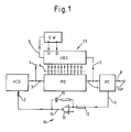
- FIG. 1 shows a block schematic circuit diagram of a frequency synthesizer made in accordance with the invention.
- a voltage controlled oscillator VCO is provided, the output frequency of which, at terminal 1, forms the synthesizer output.
- VCO comprises a frequency control voltage input terminal 2 to which a control voltage is applied to set the value of the VCO frequency.
- the VCO may comprise an oscillator having a tuned circuit in which the capacitance includes a varactor diode. The control voltage is applied as a reverse bias to the diode, the value of the capacitance being controlled by the value of the control voltage.
- Such voltage controlled oscillators are well known in the art and will not be described further. By way of illustration numerical values will be given for one specific design of swept frequency synthesizer. In this design the VCO frequency is swept from 10 to 11 MHz and it is assumed that the requirement is to make this sweep of frequency in 10 milliseconds. It will be shown later that in this case the reference frequency required is 10 KHz.
- a programmable frequency divider PD is connected to receive the VCO output as a sinusoidal signal on input 3, convert it to pulse form, and to divide the pulse frequency by a selectively variable integer N.
- N the initial value
- N i of N 1000
- N f the final value
- the programmable divider PD of this design consists of a group of four divide-by-ten counters connected in series and which can each be set to an initial count.
- the divider counters are connected to count down from a set value N to zero at which an output pulse is provided on output 4.
- the divide-by-ten counters of PD may each be an integrated circuit, for example, a TEXAS 74 LS 161 (Trade Mark).
- Control means 15 are provided for setting the value of N in the divider PD.
- the control means comprise an up/down counter UDC and switching means SW for switching UDC to count up U from a first count to a second count and then to count down D to the first count.
- UDC provides an output on connection 5 to switch SW when UDC reaches the first or the second count, N i or N f respectively.
- UDC provides outputs in binary coded decimal on connections 6 to set integer N into PD.
- the output 4 from PD is fed to UDC on connection 7 to increase, or decrease, the count Nin UDC by unity and to set the increased count, N + 1, into PD.
- UDC may comprise two TEXAS 74 LS 190 integrated circuits in this design.
- the output 4 from PD is also fed to a phase comparator PC.
- a reference frequency F ref 10 KHz in this specific design, is applied to PD on input 8.
- PD provides a d.c. output signal on connection 9 which is zero if the phases of F ref and output 4 are equal and is increasingly positive or negative in value as the phase of output 4 is increasingly in retard or in advance respectively of the phase of F ref .
- British Patent Specification No. 1,462,408 describes such a phase comparator and the circuit details will not be described further here.
- Output 9, the phase error signal, is fed to the frequency control input terminal 2 of VCO via a loop filter 10 which comprises an integrator.
- the integrator comprises a high gain d.c. amplifier 11.
- An input resistor 12 is connected to the negative input terminal of the amplifier and to output 9.
- An integrating capacitor 13 is connected between the positive output 14 of the amplifier and its negative input.
- a steady, non-zero, value on output 9 produces a steadily increasing voltage on output 14.
- a constant phase difference between the divider output 4 and F ref produces a steadily increasing output frequency from VCO.
- the connections of the loop are arranged so that, if output 4 falls behind F re f in phase, the phase error signal 9 produces an increase in the rate of rise of VCO frequency and hence, via PD, produces an advance in phase of output 4 to correct the phase lag.
- the intervals between successive output pulses 4 may be referred to as the comparison period.
- the successive increases in the integer N necessarily follow at intervals of the F ref period, which may be chosen to be highly stable.
- the rate of increase of VCO frequency must have been such that one more VCO cycle has been fitted into the comparison period as compared with the previous comparison period.
- the VCO frequency increases by a constant amount in each comparison period and hence is a closely linear increase.
- the linearity of the VCO output frequency as a function of time is dependent only to a very small degree on the linearity of VCO frequency as a function of the frequency control input voltage 2.
- the rate of rise of VCO frequency with control input 2 may fall off with increasing control voltage. The effect will be to produce a slight increase in phase error at each comparison period which in turn will produce an increase of integrator input. This then produces an increase in the rate of rise of control input voltage 2 which provides constant rate of rise of VCO frequency.
- this swept frequency synthesizer When the count in UDC has risen to 1100, a switch output on connection 5 is provided to change UDC from counting up to counting down. Similarly when the UDC count falls to 1000 the switch output changes UDC to counting up.
- this swept frequency synthesizer generates a triangular sweep of frequency.
- the design equation for a swept frequency synthesizer made in accordance with the invention can be derived as follows. If the initial output frequency is F i , the final output frequency is F f , and the reference frequency is F ref , then where N i and N f are the initial and final values of the division ratio N of the programmable divider. The total number S of values of N during the whole ramp is given by The changes of N are made at intervals of the periodic time, 1/F ref , of the reference frequency, herein termed the comparison period.
- T (F f - F i )/(F ref )2 (3) from which The quantity under the square root sign of equation (4) is the slope of the ramp in Hertz per second, i.e. the rate of change of frequency.
- Equation 3 then allows the ramp duration T to be calculated and, as before, equations (a) and (b) give the values of N i and N f .
- N is then incremented by an integer m at each comparison period.
- T (F f - F i )/(m F ref )2 (6) and If F f , F i and F ref are held constant and m is increased to values 2, 3, 4, ... etc., the ramp time T decreases in proportion.
- a successive addition rate multiplier a range of ramp rates between the same initial and final values of frequency can be obtained.
- the value of M may be non-integer if the synthesizer incorporates the phase predict technique as described in British Patent Specification 1,447,418 or the improved phase predict technique as described in British Patent Specification 2,068,185.
Landscapes
- Stabilization Of Oscillater, Synchronisation, Frequency Synthesizers (AREA)
Applications Claiming Priority (2)
| Application Number | Priority Date | Filing Date | Title |
|---|---|---|---|
| GB8727564A GB2213000A (en) | 1987-11-25 | 1987-11-25 | Frequency synthesizer |
| GB8727564 | 1987-11-25 |
Publications (2)
| Publication Number | Publication Date |
|---|---|
| EP0318114A2 true EP0318114A2 (de) | 1989-05-31 |
| EP0318114A3 EP0318114A3 (de) | 1990-07-11 |
Family
ID=10627504
Family Applications (1)
| Application Number | Title | Priority Date | Filing Date |
|---|---|---|---|
| EP88202656A Withdrawn EP0318114A3 (de) | 1987-11-25 | 1988-11-24 | Frequenzsynthesierer |
Country Status (4)
| Country | Link |
|---|---|
| US (1) | US4931749A (de) |
| EP (1) | EP0318114A3 (de) |
| JP (1) | JPH01168122A (de) |
| GB (1) | GB2213000A (de) |
Cited By (3)
| Publication number | Priority date | Publication date | Assignee | Title |
|---|---|---|---|---|
| DE4224035A1 (de) * | 1992-07-21 | 1994-01-27 | Siemens Ag | Ultraschallprüfverfahren |
| WO2001063742A1 (en) * | 2000-02-25 | 2001-08-30 | Infineon Technologies Ag | Swept frequency phase locked loop |
| EP1289150A1 (de) * | 2001-08-24 | 2003-03-05 | STMicroelectronics S.r.l. | Verfahren zum Erzeugen eines Signals veränderbarer Frequenz, zum Beispiel zum Spreizen des Sprektrums eines Taktsignals, und Vorrichtung dafür |
Families Citing this family (8)
| Publication number | Priority date | Publication date | Assignee | Title |
|---|---|---|---|---|
| SE9103098D0 (sv) * | 1991-10-24 | 1991-10-24 | Joergen Johansson | Anordning vid tv-system |
| US5369376A (en) * | 1991-11-29 | 1994-11-29 | Standard Microsystems, Inc. | Programmable phase locked loop circuit and method of programming same |
| US6072426A (en) * | 1996-08-15 | 2000-06-06 | Alliedsignal Inc. | Modulator slope calibration circuit |
| US6008754A (en) * | 1996-08-15 | 1999-12-28 | Alliedsignal Inc. | On-ground radio altimeter calibration system |
| US6611160B1 (en) | 2000-11-21 | 2003-08-26 | Skyworks Solutions, Inc. | Charge pump having reduced switching noise |
| US6466069B1 (en) | 2000-11-21 | 2002-10-15 | Conexant Systems, Inc. | Fast settling charge pump |
| JP5317851B2 (ja) * | 2009-06-26 | 2013-10-16 | 新日本無線株式会社 | 周波数掃引回路 |
| JP2011055477A (ja) * | 2009-08-07 | 2011-03-17 | Rohm Co Ltd | スイープ機能付きオシレータ回路およびそれを用いたモータ駆動装置 |
Family Cites Families (7)
| Publication number | Priority date | Publication date | Assignee | Title |
|---|---|---|---|---|
| US3364437A (en) * | 1966-12-09 | 1968-01-16 | Ltv Electrosystems Inc | Precision swept oscillator |
| FR2256582B1 (de) * | 1973-12-27 | 1976-11-19 | Trt Telecom Radio Electr | |
| US3898579A (en) * | 1974-01-02 | 1975-08-05 | Motorola Inc | Frequency control circuits for phase locked loop frequency synthesizers |
| GB2068185B (en) * | 1980-01-21 | 1983-06-22 | Philips Electronic Associated | Frequency synthesiser of the phase lock loop type |
| GB2091960B (en) * | 1981-01-27 | 1985-06-19 | Int Standard Electric Corp | High speed frequency synthesizer |
| GB2124047A (en) * | 1982-07-10 | 1984-02-08 | Plessey Co Plc | Frequency synthesiser |
| FR2548488B1 (fr) * | 1983-06-28 | 1985-10-18 | Thomson Csf | Dispositif de generation d'un signal module en frequence |
-
1987
- 1987-11-25 GB GB8727564A patent/GB2213000A/en not_active Withdrawn
-
1988
- 1988-10-17 US US07/258,404 patent/US4931749A/en not_active Expired - Fee Related
- 1988-11-24 EP EP88202656A patent/EP0318114A3/de not_active Withdrawn
- 1988-11-25 JP JP63296427A patent/JPH01168122A/ja active Pending
Cited By (4)
| Publication number | Priority date | Publication date | Assignee | Title |
|---|---|---|---|---|
| DE4224035A1 (de) * | 1992-07-21 | 1994-01-27 | Siemens Ag | Ultraschallprüfverfahren |
| WO2001063742A1 (en) * | 2000-02-25 | 2001-08-30 | Infineon Technologies Ag | Swept frequency phase locked loop |
| EP1289150A1 (de) * | 2001-08-24 | 2003-03-05 | STMicroelectronics S.r.l. | Verfahren zum Erzeugen eines Signals veränderbarer Frequenz, zum Beispiel zum Spreizen des Sprektrums eines Taktsignals, und Vorrichtung dafür |
| US7079616B2 (en) | 2001-08-24 | 2006-07-18 | Stmicroelectronics S.R.L. | Process for generating a variable frequency signal, for instance for spreading the spectrum of a clock signal, and device therefor |
Also Published As
| Publication number | Publication date |
|---|---|
| GB2213000A (en) | 1989-08-02 |
| US4931749A (en) | 1990-06-05 |
| EP0318114A3 (de) | 1990-07-11 |
| GB8727564D0 (en) | 1988-04-27 |
| JPH01168122A (ja) | 1989-07-03 |
Similar Documents
| Publication | Publication Date | Title |
|---|---|---|
| US5920233A (en) | Phase locked loop including a sampling circuit for reducing spurious side bands | |
| EP0897616B1 (de) | Frequenzsynthetisierer mit temperaturkompensation und frequenzvervielfachung sowie verfahren dafür | |
| US4573026A (en) | FM Modulator phase-locked loop with FM calibration | |
| US4516084A (en) | Frequency synthesizer using an arithmetic frequency synthesizer and plural phase locked loops | |
| US4546331A (en) | Frequency modulation in a phase-locked loop | |
| US4931749A (en) | Phase locked loop sweep frequency synthesizer | |
| EP0193273A2 (de) | Synthesizer | |
| EP0945715A2 (de) | Anordnung zur präzisen Entfernungsmessung, insbesondere zur Füllstandsmessung | |
| US4105946A (en) | Frequency synthesizer with phase locked loop and counter | |
| US4458214A (en) | Fast sampling phase locked loop frequency synthesizer | |
| US4388597A (en) | Frequency synthesizer having plural phase locked loops | |
| US4144579A (en) | Arithmetic synthesizer frequency generation with reduced phase jitter | |
| EP0557799A1 (de) | Frequenzsynthetisierer mit gebrochenem Teilverhältnis mit Digitalfehlerkorrektion und Verfahren | |
| US20040212410A1 (en) | Reduced-size integrated phase-locked loop | |
| KR100417752B1 (ko) | 고주파신호의주파수변조방법및장치 | |
| US4583059A (en) | Adjustable frequency crystal oscillator with temperature compensation | |
| GB2063605A (en) | Oscillator circuit | |
| US5216374A (en) | Frequency synthesizer utilizing pulse-width modulation of digital VCO control signal | |
| GB2107142A (en) | Frequency synthesisers | |
| US4859968A (en) | Frequency generator | |
| US5521532A (en) | Digital synthesizer controlled microwave frequency signal source | |
| US4119925A (en) | Frequency synthesizer with frequency modulated output | |
| JPH0553081B2 (de) | ||
| EP0203756A2 (de) | Frequenzsynthesierer | |
| US4320355A (en) | Sweep signal generation system |
Legal Events
| Date | Code | Title | Description |
|---|---|---|---|
| PUAI | Public reference made under article 153(3) epc to a published international application that has entered the european phase |
Free format text: ORIGINAL CODE: 0009012 |
|
| AK | Designated contracting states |
Kind code of ref document: A2 Designated state(s): DE FR GB IT |
|
| PUAL | Search report despatched |
Free format text: ORIGINAL CODE: 0009013 |
|
| AK | Designated contracting states |
Kind code of ref document: A3 Designated state(s): DE FR GB IT |
|
| 17P | Request for examination filed |
Effective date: 19901219 |
|
| RAP3 | Party data changed (applicant data changed or rights of an application transferred) |
Owner name: N.V. PHILIPS' GLOEILAMPENFABRIEKEN Owner name: PHILIPS ELECTRONICS UK LIMITED |
|
| 17Q | First examination report despatched |
Effective date: 19930407 |
|
| STAA | Information on the status of an ep patent application or granted ep patent |
Free format text: STATUS: THE APPLICATION HAS BEEN WITHDRAWN |
|
| 18W | Application withdrawn |
Withdrawal date: 19941130 |