EP0318131A1 - Procédé et dispositif de fabrication d'aimants permanents extrudés - Google Patents
Procédé et dispositif de fabrication d'aimants permanents extrudés Download PDFInfo
- Publication number
- EP0318131A1 EP0318131A1 EP88304916A EP88304916A EP0318131A1 EP 0318131 A1 EP0318131 A1 EP 0318131A1 EP 88304916 A EP88304916 A EP 88304916A EP 88304916 A EP88304916 A EP 88304916A EP 0318131 A1 EP0318131 A1 EP 0318131A1
- Authority
- EP
- European Patent Office
- Prior art keywords
- core
- permanent magnet
- charge
- container
- assembly
- Prior art date
- Legal status (The legal status is an assumption and is not a legal conclusion. Google has not performed a legal analysis and makes no representation as to the accuracy of the status listed.)
- Granted
Links
- 238000000034 method Methods 0.000 title claims description 18
- 239000002245 particle Substances 0.000 claims abstract description 17
- 229910045601 alloy Inorganic materials 0.000 claims abstract description 15
- 239000000956 alloy Substances 0.000 claims abstract description 15
- 238000004519 manufacturing process Methods 0.000 claims abstract description 7
- 239000000203 mixture Substances 0.000 claims abstract description 4
- 238000001125 extrusion Methods 0.000 claims description 32
- 229910000975 Carbon steel Inorganic materials 0.000 claims description 7
- 239000010962 carbon steel Substances 0.000 claims description 7
- 229910052761 rare earth metal Inorganic materials 0.000 claims description 5
- 239000010935 stainless steel Substances 0.000 claims description 4
- 229910001220 stainless steel Inorganic materials 0.000 claims description 4
- 239000000463 material Substances 0.000 claims description 3
- 239000000696 magnetic material Substances 0.000 claims description 2
- 238000010438 heat treatment Methods 0.000 claims 1
- 239000007787 solid Substances 0.000 description 6
- 239000000843 powder Substances 0.000 description 3
- XEEYBQQBJWHFJM-UHFFFAOYSA-N Iron Chemical compound [Fe] XEEYBQQBJWHFJM-UHFFFAOYSA-N 0.000 description 2
- 229910052799 carbon Inorganic materials 0.000 description 2
- 239000013078 crystal Substances 0.000 description 2
- 239000000835 fiber Substances 0.000 description 2
- CPLXHLVBOLITMK-UHFFFAOYSA-N magnesium oxide Inorganic materials [Mg]=O CPLXHLVBOLITMK-UHFFFAOYSA-N 0.000 description 2
- 239000000395 magnesium oxide Substances 0.000 description 2
- AXZKOIWUVFPNLO-UHFFFAOYSA-N magnesium;oxygen(2-) Chemical compound [O-2].[Mg+2] AXZKOIWUVFPNLO-UHFFFAOYSA-N 0.000 description 2
- 230000007704 transition Effects 0.000 description 2
- ZOXJGFHDIHLPTG-UHFFFAOYSA-N Boron Chemical compound [B] ZOXJGFHDIHLPTG-UHFFFAOYSA-N 0.000 description 1
- OKTJSMMVPCPJKN-UHFFFAOYSA-N Carbon Chemical compound [C] OKTJSMMVPCPJKN-UHFFFAOYSA-N 0.000 description 1
- 229910052692 Dysprosium Inorganic materials 0.000 description 1
- 229910052779 Neodymium Inorganic materials 0.000 description 1
- 229910052772 Samarium Inorganic materials 0.000 description 1
- 229910000831 Steel Inorganic materials 0.000 description 1
- 238000000889 atomisation Methods 0.000 description 1
- 229910052796 boron Inorganic materials 0.000 description 1
- 239000010941 cobalt Substances 0.000 description 1
- 229910017052 cobalt Inorganic materials 0.000 description 1
- GUTLYIVDDKVIGB-UHFFFAOYSA-N cobalt atom Chemical compound [Co] GUTLYIVDDKVIGB-UHFFFAOYSA-N 0.000 description 1
- 238000005056 compaction Methods 0.000 description 1
- 238000007596 consolidation process Methods 0.000 description 1
- 238000010276 construction Methods 0.000 description 1
- 238000007796 conventional method Methods 0.000 description 1
- 238000009792 diffusion process Methods 0.000 description 1
- KBQHZAAAGSGFKK-UHFFFAOYSA-N dysprosium atom Chemical compound [Dy] KBQHZAAAGSGFKK-UHFFFAOYSA-N 0.000 description 1
- 230000004907 flux Effects 0.000 description 1
- 229910052742 iron Inorganic materials 0.000 description 1
- QEFYFXOXNSNQGX-UHFFFAOYSA-N neodymium atom Chemical compound [Nd] QEFYFXOXNSNQGX-UHFFFAOYSA-N 0.000 description 1
- 238000010943 off-gassing Methods 0.000 description 1
- 238000004663 powder metallurgy Methods 0.000 description 1
- 238000003825 pressing Methods 0.000 description 1
- 239000011802 pulverized particle Substances 0.000 description 1
- KZUNJOHGWZRPMI-UHFFFAOYSA-N samarium atom Chemical compound [Sm] KZUNJOHGWZRPMI-UHFFFAOYSA-N 0.000 description 1
- 238000007789 sealing Methods 0.000 description 1
- 238000005245 sintering Methods 0.000 description 1
- 239000010959 steel Substances 0.000 description 1
- 238000003466 welding Methods 0.000 description 1
Images

Classifications
-
- H—ELECTRICITY
- H01—ELECTRIC ELEMENTS
- H01F—MAGNETS; INDUCTANCES; TRANSFORMERS; SELECTION OF MATERIALS FOR THEIR MAGNETIC PROPERTIES
- H01F1/00—Magnets or magnetic bodies characterised by the magnetic materials therefor; Selection of materials for their magnetic properties
- H01F1/01—Magnets or magnetic bodies characterised by the magnetic materials therefor; Selection of materials for their magnetic properties of inorganic materials
- H01F1/03—Magnets or magnetic bodies characterised by the magnetic materials therefor; Selection of materials for their magnetic properties of inorganic materials characterised by their coercivity
- H01F1/032—Magnets or magnetic bodies characterised by the magnetic materials therefor; Selection of materials for their magnetic properties of inorganic materials characterised by their coercivity of hard-magnetic materials
- H01F1/04—Magnets or magnetic bodies characterised by the magnetic materials therefor; Selection of materials for their magnetic properties of inorganic materials characterised by their coercivity of hard-magnetic materials metals or alloys
- H01F1/06—Magnets or magnetic bodies characterised by the magnetic materials therefor; Selection of materials for their magnetic properties of inorganic materials characterised by their coercivity of hard-magnetic materials metals or alloys in the form of particles, e.g. powder
- H01F1/08—Magnets or magnetic bodies characterised by the magnetic materials therefor; Selection of materials for their magnetic properties of inorganic materials characterised by their coercivity of hard-magnetic materials metals or alloys in the form of particles, e.g. powder pressed, sintered, or bound together
- H01F1/083—Magnets or magnetic bodies characterised by the magnetic materials therefor; Selection of materials for their magnetic properties of inorganic materials characterised by their coercivity of hard-magnetic materials metals or alloys in the form of particles, e.g. powder pressed, sintered, or bound together in a bonding agent
-
- B—PERFORMING OPERATIONS; TRANSPORTING
- B22—CASTING; POWDER METALLURGY
- B22F—WORKING METALLIC POWDER; MANUFACTURE OF ARTICLES FROM METALLIC POWDER; MAKING METALLIC POWDER; APPARATUS OR DEVICES SPECIALLY ADAPTED FOR METALLIC POWDER
- B22F3/00—Manufacture of workpieces or articles from metallic powder characterised by the manner of compacting or sintering; Apparatus specially adapted therefor ; Presses and furnaces
- B22F3/20—Manufacture of workpieces or articles from metallic powder characterised by the manner of compacting or sintering; Apparatus specially adapted therefor ; Presses and furnaces by extruding
-
- H—ELECTRICITY
- H01—ELECTRIC ELEMENTS
- H01F—MAGNETS; INDUCTANCES; TRANSFORMERS; SELECTION OF MATERIALS FOR THEIR MAGNETIC PROPERTIES
- H01F41/00—Apparatus or processes specially adapted for manufacturing or assembling magnets, inductances or transformers; Apparatus or processes specially adapted for manufacturing materials characterised by their magnetic properties
- H01F41/02—Apparatus or processes specially adapted for manufacturing or assembling magnets, inductances or transformers; Apparatus or processes specially adapted for manufacturing materials characterised by their magnetic properties for manufacturing cores, coils, or magnets
- H01F41/0253—Apparatus or processes specially adapted for manufacturing or assembling magnets, inductances or transformers; Apparatus or processes specially adapted for manufacturing materials characterised by their magnetic properties for manufacturing cores, coils, or magnets for manufacturing permanent magnets
- H01F41/0266—Moulding; Pressing
Definitions
- This invention relates to a method and assembly for producing extruded permanent magnet articles from particle charges of permanent magnet alloys.
- Uniaxial anisotropic crystal alignment is not always advantageous for magnet applications for rotating machinery, motor rotors, beam focussing devices and the like.
- a [100] fibre texture wherein the C crystallographic axis is perpendicular to the axis of the magnet may be desired.
- One of the primary applications for magnets of this construction is for use in DC motors.
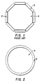
- multiple segments of uniaxial anistropic magnets are needed to form the armature for the motor, which segments are identified as 2 positioned around a motor shaft 4 in Fig. 1.
- Cylindrical, extruded magnets as shown in Fig. 2, are conventionally produced by the use of a cylindrical extrusion container. Magnet alloy particles are introduced to the container, and the container is outgassed, evacuated and sealed. Thereafter, the container is heated to extrusion temperature and extruded to consolidate the particles to substantially full density.
- the hollow centre of the magnet is achieved by the use of a solid cylinder or mandrel of a diameter corresponding to the internal diameter of the magnet to be produced, which cylinder is attached to the extrusion ram. This solid cylinder moves with the extrusion ram during the extrusion operation and thereby maintains the desired inner diameter of the extruded magnet.
- Another object of the invention is a method and assembly for use therewith that enables the production of a complete assembly, including a permanent magnet and associated shaft in a single extrusion operation.
- a particle charge is provided of a permanent magnet alloy composition from which the permanent magnet article is to be made.
- the particle charge is placed in a cylindrical container having a generally axially positioned core with the charge surrounding the core within the container.
- the container is evacuated and sealed against the atmosphere.
- the container and particle charge are heated to elevated temperature and the container and charge are then extruded to compact the charge to substantially full density to thereby produce a substantially fully dense permanent magnet article.
- a separating medium such as magnesium oxide, may be provided on the core.
- the core may be of carbon steel, a soft magnet material or stainless steel. During the extrusion operation, the core may be bonded to the permanent magnet alloy. This is advantageous from the standpoint of producing a unitary magnet and shaft assembly during the extrusion operation.
- Extrusion ratios within the range of 1.5:1 to 50:1 may be employed with extrusion temperatures within the range of 500 to 1200°C.
- the method of the invention finds particular use in producing rare earth element containing permanent magnets. More specifically, it may be used in the production of magnets of this type wherein at least one rare earth element, such as samarium, neodymium and dysprosium, may be used with a transition element, such as iron and cobalt, plus boron and/or carbon.
- at least one rare earth element such as samarium, neodymium and dysprosium
- a transition element such as iron and cobalt, plus boron and/or carbon.
- the invention also provides an assembly for use in producing a compacted, fully dense permanent magnet article by extrusion including a cylindrical container having a core generally axially positioned therein.
- the mandrel defines an annular chamber within the container.
- a particle charge of a permanent magnet alloy from which the article is to be made is provided within this annular chamber.
- Means are provided for sealing the annular chamber.
- a separating medium may be provided on the core. This facilitates removal of the core from the compacted magnet after extrusion.
- the core may be constructed of carbon steel, a soft magnet material or stainless steel.
- a cylindrical container 8 having end plates 10 with axial openings 11 connected at opposite ends of the container, as by welding (not shown) to seal the container.
- a solid core 12 is connected at opposite ends thereof to the plates 10 and a portion extends through openings 11.
- the core is axially positioned within the container 8 to define therein an annular chamber 14 surrounding the core. Particles P of the magnet alloy composition from which the magnet is to be constructed are provided within the annular chamber 14 of the container 8.
- Figs.3 and 4 so constructed is then after outgassing heated to extrusion temperature and extruded in conventional extruding apparatus to compact the particles in the container to substantially full density.
- the core 12 may be removed from the compacted hollow cylindrical magnet. This may be facilitated by having the core provided with a separating medium, such as magnesium oxide, on the surface thereof. Alternately, the core may be bonded to the cylindrical magnet for use as an assembly in the production of a conventional motor rotor, as shown in Fig. 2.
- a carbon steel extrusion container was made with a solid low-carbon rod, 3/4" (19mm) in diameter, welded axially to the top and bottom plates of a mild carbon steel can.
- Atomized (NdDy)15Fe79B6 powder was put into the 3-1/8" (79.38mm) diameter can and the can was heated to 150°C, evacuated and sealed. The container was then heated to 927°C and extruded with a ratio of 13.8:1.
- the final extrusion consisted of a 0.3" (7.62mm) diameter steel rod surrounded by a ring shaped magnet with a wall thickness of about 0.25" (6.35mm).
- the magnetic properties are listed in Table 1. The identical properties along two orthogonal directions perpendicular to the extrusion direction indicates that a [100] fibre texture is obtained. This is the same magnetic behaviour as is observed for magnets extruded by conventional methods.
- Example 1 To compare the practice of Example 1 with a conventional practice, the identical powder used in Example 1, (NdDy) 15FE79B6, was placed into a 3-1/8" (79.38mm) diameter can and the can was heated to 150°C, evacuated and sealed. The can was then heated to 927°C and extruded with a ratio of 13.8:1.
- the magnetic properties of the resultant solid cylinder are presented in Table II. The magnetic properties are very similar to those obtained in Example 1.
- the extrusion technique of Example 1 in accordance with the invention will produce magnetic properties comparable to a conventional magnet extrusion method.
- the same powder as used in Examples 1 and 2 was placed in a carbon steel extrusion container.
- This extrusion container was in the shape of a hollow circular cylinder, 3-1/8" (79.38mm) OD and 3/4" (19mm) ID.
- the container was evacuated, sealed and heated to 927°C and extruded at a 10:1 extrusion ratio.
- the inner diameter was maintained during extrusion by affixing a solid mandrel to the ram of the extrusion press in accordance with conventional practice.
- the magnetic properties, Table III are similar to the properties presented in Tables I and II.
- the invention provides for the production of a hollow permanent magnet by an extrusion practice wherein the desired dimensions of the magnet may be maintained while achieving permanent magnet properties comparable to conventional practices used for this purpose.
- the shape of the core may include symmetrical geometries other than cylindrical.
- the particles of magnetic material for compaction may be produced by atomization, rapidly solidified ribbon, cast and pulverized particles, direct cast ingots or particles made by a reduction-diffusion practice.
- an assembly may be produced having an outer shell of a permanent magnet alloy and a soft magnetic inner core, with the inner core acting to direct magnetic flux.
Landscapes
- Engineering & Computer Science (AREA)
- Power Engineering (AREA)
- Manufacturing & Machinery (AREA)
- Mechanical Engineering (AREA)
- Manufacturing Cores, Coils, And Magnets (AREA)
- Powder Metallurgy (AREA)
- Extrusion Moulding Of Plastics Or The Like (AREA)
Priority Applications (1)
| Application Number | Priority Date | Filing Date | Title |
|---|---|---|---|
| AT88304916T ATE87764T1 (de) | 1987-11-18 | 1988-05-31 | Verfahren und vorrichtung zur herstellung von stranggepressten koerpern aus dauermagnetischem material. |
Applications Claiming Priority (2)
| Application Number | Priority Date | Filing Date | Title |
|---|---|---|---|
| US12235187A | 1987-11-18 | 1987-11-18 | |
| US122351 | 1998-07-24 |
Publications (2)
| Publication Number | Publication Date |
|---|---|
| EP0318131A1 true EP0318131A1 (fr) | 1989-05-31 |
| EP0318131B1 EP0318131B1 (fr) | 1993-03-31 |
Family
ID=22402192
Family Applications (1)
| Application Number | Title | Priority Date | Filing Date |
|---|---|---|---|
| EP88304916A Expired - Lifetime EP0318131B1 (fr) | 1987-11-18 | 1988-05-31 | Procédé et dispositif de fabrication d'aimants permanents extrudés |
Country Status (6)
| Country | Link |
|---|---|
| EP (1) | EP0318131B1 (fr) |
| JP (1) | JPH01151216A (fr) |
| AT (1) | ATE87764T1 (fr) |
| CA (1) | CA1301602C (fr) |
| DE (1) | DE3879886T2 (fr) |
| ES (1) | ES2040341T3 (fr) |
Families Citing this family (1)
| Publication number | Priority date | Publication date | Assignee | Title |
|---|---|---|---|---|
| DE10312102B4 (de) * | 2003-03-19 | 2015-10-08 | Robert Bosch Gmbh | Vorrichtung zur Messung eines Füllstandes einer Flüssigkeit in einem Behälter |
Citations (7)
| Publication number | Priority date | Publication date | Assignee | Title |
|---|---|---|---|---|
| US3447230A (en) * | 1967-01-05 | 1969-06-03 | Sylvania Electric Prod | Art of making seamless hollow bodies from sinterable powders |
| US3918867A (en) * | 1969-06-28 | 1975-11-11 | Philips Corp | Device for extruding permanent magnet bodies |
| GB1534221A (en) * | 1977-07-25 | 1978-11-29 | Ipari Szerelveny & Gepgyar | Process for the production of sleeves and like workpieces from hard metals of high cobalt content |
| EP0092422A2 (fr) * | 1982-04-19 | 1983-10-26 | Matsushita Electric Industrial Co., Ltd. | Aimant permanent en alliage de Mn-Al-C et procédé de fabrication |
| US4640815A (en) * | 1985-10-17 | 1987-02-03 | Crucible Materials Corporation | Method and assembly for producing extrusion-clad tubular product |
| EP0231620A2 (fr) * | 1986-01-29 | 1987-08-12 | General Motors Corporation | Fabrication d'un aimant permanent à partir d'un alliage cristallin à coercitivité très faible de terre rare-métal de transition-bore |
| EP0240420A1 (fr) * | 1986-03-29 | 1987-10-07 | Shin-Etsu Chemical Co., Ltd. | Procédé pour la fabrication d'une barre extrudée de longueur continue en aimant plastique avec aimantation multipolaire en périphérie |
Family Cites Families (5)
| Publication number | Priority date | Publication date | Assignee | Title |
|---|---|---|---|---|
| JPS5120592A (en) * | 1974-08-13 | 1976-02-18 | Matsushita Electric Industrial Co Ltd | Kyojiseitaifunmatsuno jikaichuseikeiyokanagata |
| JPS5176108A (ja) * | 1974-12-27 | 1976-07-01 | Hitachi Metals Ltd | Funmatsuyakinhonyorukanseizoho oyobifunmatsujutenyoki |
| JPS60214515A (ja) * | 1984-04-10 | 1985-10-26 | Seiko Epson Corp | 円筒状永久磁石の製造方法 |
| JPH0626169B2 (ja) * | 1984-12-27 | 1994-04-06 | ティーディーケイ株式会社 | 希土類磁石の磁場中成型方法及び装置 |
| US4602952A (en) * | 1985-04-23 | 1986-07-29 | Cameron Iron Works, Inc. | Process for making a composite powder metallurgical billet |
-
1988
- 1988-05-04 CA CA000565893A patent/CA1301602C/fr not_active Expired - Fee Related
- 1988-05-31 ES ES198888304916T patent/ES2040341T3/es not_active Expired - Lifetime
- 1988-05-31 DE DE8888304916T patent/DE3879886T2/de not_active Expired - Fee Related
- 1988-05-31 AT AT88304916T patent/ATE87764T1/de not_active IP Right Cessation
- 1988-05-31 EP EP88304916A patent/EP0318131B1/fr not_active Expired - Lifetime
- 1988-10-04 JP JP63249177A patent/JPH01151216A/ja active Pending
Patent Citations (7)
| Publication number | Priority date | Publication date | Assignee | Title |
|---|---|---|---|---|
| US3447230A (en) * | 1967-01-05 | 1969-06-03 | Sylvania Electric Prod | Art of making seamless hollow bodies from sinterable powders |
| US3918867A (en) * | 1969-06-28 | 1975-11-11 | Philips Corp | Device for extruding permanent magnet bodies |
| GB1534221A (en) * | 1977-07-25 | 1978-11-29 | Ipari Szerelveny & Gepgyar | Process for the production of sleeves and like workpieces from hard metals of high cobalt content |
| EP0092422A2 (fr) * | 1982-04-19 | 1983-10-26 | Matsushita Electric Industrial Co., Ltd. | Aimant permanent en alliage de Mn-Al-C et procédé de fabrication |
| US4640815A (en) * | 1985-10-17 | 1987-02-03 | Crucible Materials Corporation | Method and assembly for producing extrusion-clad tubular product |
| EP0231620A2 (fr) * | 1986-01-29 | 1987-08-12 | General Motors Corporation | Fabrication d'un aimant permanent à partir d'un alliage cristallin à coercitivité très faible de terre rare-métal de transition-bore |
| EP0240420A1 (fr) * | 1986-03-29 | 1987-10-07 | Shin-Etsu Chemical Co., Ltd. | Procédé pour la fabrication d'une barre extrudée de longueur continue en aimant plastique avec aimantation multipolaire en périphérie |
Non-Patent Citations (2)
| Title |
|---|
| PATENT ABSTRACTS OF JAPAN, vol. 7, no. 4 (E-151)[1149], 8th January 1983; & JP-A-57 164 509 (FUJI XEROX K.K.) 09-10-1982 * |
| PATENT ABSTRACTS OF JAPAN, vol. 8, No. 213 (E-269)[1650], 28th September 1984; & JP-A-59 99 705 (SUWA SEIKOSHA K.K.) 08-06-1984 * |
Also Published As
| Publication number | Publication date |
|---|---|
| CA1301602C (fr) | 1992-05-26 |
| JPH01151216A (ja) | 1989-06-14 |
| DE3879886D1 (de) | 1993-05-06 |
| EP0318131B1 (fr) | 1993-03-31 |
| DE3879886T2 (de) | 1993-08-26 |
| ATE87764T1 (de) | 1993-04-15 |
| ES2040341T3 (es) | 1993-10-16 |
Similar Documents
| Publication | Publication Date | Title |
|---|---|---|
| EP0418304B1 (fr) | Procede de construction d'un rotor a aimant permanent | |
| US4151435A (en) | Stator structure using forming curved wafer thin magnets from rare earth-cobalt alloy powders | |
| JP5963870B2 (ja) | 永久磁石の製造方法、および永久磁石の製造装置 | |
| US5223759A (en) | DC brushless motor with solid rotor having permanent magnet | |
| US5039292A (en) | Device for manufacturing magnetically anisotropic magnets | |
| US3977918A (en) | Method of making magnets | |
| US6423264B1 (en) | Process for forming rotating electromagnets having soft and hard magnetic components | |
| US4325757A (en) | Method of forming thin curved rare earth-transition metal magnets from lightly compacted powder preforms | |
| DE19728418A1 (de) | Herstellungsverfahren für anisotrope harzgebundene Magneten | |
| EP1895551B1 (fr) | Procede de production d'un aimant radialement anisotrope | |
| US4881984A (en) | Consolidation of magnet alloy powders by extrusion and product therefrom | |
| EP1717828A1 (fr) | Procédé de fabrication d"un aimant fritté cylindrique anisotrope radial et aimant multipolaire cylindrique pour utilisation avec moteur à aimant permanent | |
| US4628809A (en) | Radial orientation rare earth-cobalt magnet rings | |
| JP2008263242A (ja) | 磁気異方性希土類焼結磁石の製造方法及び製造装置 | |
| EP1713098A1 (fr) | Aimant fritté cylindrique anisotrope radial et moteur à aimant permanent | |
| US4533407A (en) | Radial orientation rare earth-cobalt magnet rings | |
| US5047205A (en) | Method and assembly for producing extruded permanent magnet articles | |
| EP0318131B1 (fr) | Procédé et dispositif de fabrication d'aimants permanents extrudés | |
| US4144060A (en) | Method of fabricating rare earth-transition metal magnets | |
| EP0565363B1 (fr) | Méthode de production d'un aimant de terre rare anisotrope | |
| US5342574A (en) | Method for producing anisotropic rare earth magnet | |
| JPH03265102A (ja) | 径方向異方性円筒状永久磁石及びその製造方法 | |
| RU2051456C1 (ru) | Способ изготовления магнитопроводов электрических машин и аппаратов | |
| DE68906544T2 (de) | Verfahren zur herstellung eines dauermagnetischen laeufers. | |
| SU1391807A1 (ru) | Способ изготовлени многополюсных посто нных магнитов с отверстием из сплавов высококоэрцитивных магнитотвердых материалов |
Legal Events
| Date | Code | Title | Description |
|---|---|---|---|
| PUAI | Public reference made under article 153(3) epc to a published international application that has entered the european phase |
Free format text: ORIGINAL CODE: 0009012 |
|
| AK | Designated contracting states |
Kind code of ref document: A1 Designated state(s): AT BE CH DE ES FR GB GR IT LI LU NL SE |
|
| 17P | Request for examination filed |
Effective date: 19890601 |
|
| 17Q | First examination report despatched |
Effective date: 19920227 |
|
| GRAA | (expected) grant |
Free format text: ORIGINAL CODE: 0009210 |
|
| AK | Designated contracting states |
Kind code of ref document: B1 Designated state(s): AT BE CH DE ES FR GB GR IT LI LU NL SE |
|
| REF | Corresponds to: |
Ref document number: 87764 Country of ref document: AT Date of ref document: 19930415 Kind code of ref document: T |
|
| ITF | It: translation for a ep patent filed | ||
| PGFP | Annual fee paid to national office [announced via postgrant information from national office to epo] |
Ref country code: FR Payment date: 19930409 Year of fee payment: 6 |
|
| PGFP | Annual fee paid to national office [announced via postgrant information from national office to epo] |
Ref country code: DE Payment date: 19930414 Year of fee payment: 6 Ref country code: CH Payment date: 19930414 Year of fee payment: 6 |
|
| PGFP | Annual fee paid to national office [announced via postgrant information from national office to epo] |
Ref country code: SE Payment date: 19930415 Year of fee payment: 6 |
|
| PGFP | Annual fee paid to national office [announced via postgrant information from national office to epo] |
Ref country code: AT Payment date: 19930419 Year of fee payment: 6 |
|
| PGFP | Annual fee paid to national office [announced via postgrant information from national office to epo] |
Ref country code: BE Payment date: 19930422 Year of fee payment: 6 |
|
| ET | Fr: translation filed | ||
| PGFP | Annual fee paid to national office [announced via postgrant information from national office to epo] |
Ref country code: LU Payment date: 19930428 Year of fee payment: 6 |
|
| PGFP | Annual fee paid to national office [announced via postgrant information from national office to epo] |
Ref country code: GR Payment date: 19930430 Year of fee payment: 6 Ref country code: GB Payment date: 19930430 Year of fee payment: 6 |
|
| REF | Corresponds to: |
Ref document number: 3879886 Country of ref document: DE Date of ref document: 19930506 |
|
| PGFP | Annual fee paid to national office [announced via postgrant information from national office to epo] |
Ref country code: ES Payment date: 19930517 Year of fee payment: 6 |
|
| ITTA | It: last paid annual fee | ||
| PGFP | Annual fee paid to national office [announced via postgrant information from national office to epo] |
Ref country code: NL Payment date: 19930531 Year of fee payment: 6 |
|
| REG | Reference to a national code |
Ref country code: GR Ref legal event code: FG4A Free format text: 3007879 |
|
| EPTA | Lu: last paid annual fee | ||
| REG | Reference to a national code |
Ref country code: ES Ref legal event code: FG2A Ref document number: 2040341 Country of ref document: ES Kind code of ref document: T3 |
|
| PLBE | No opposition filed within time limit |
Free format text: ORIGINAL CODE: 0009261 |
|
| STAA | Information on the status of an ep patent application or granted ep patent |
Free format text: STATUS: NO OPPOSITION FILED WITHIN TIME LIMIT |
|
| 26N | No opposition filed | ||
| PG25 | Lapsed in a contracting state [announced via postgrant information from national office to epo] |
Ref country code: LU Free format text: LAPSE BECAUSE OF NON-PAYMENT OF DUE FEES Effective date: 19940531 Ref country code: LI Effective date: 19940531 Ref country code: GB Effective date: 19940531 Ref country code: CH Effective date: 19940531 Ref country code: BE Effective date: 19940531 Ref country code: AT Effective date: 19940531 |
|
| PG25 | Lapsed in a contracting state [announced via postgrant information from national office to epo] |
Ref country code: SE Effective date: 19940601 Ref country code: ES Free format text: LAPSE BECAUSE OF NON-PAYMENT OF DUE FEES Effective date: 19940601 |
|
| BERE | Be: lapsed |
Owner name: CRUCIBLE MATERIALS CORP. Effective date: 19940531 |
|
| PG25 | Lapsed in a contracting state [announced via postgrant information from national office to epo] |
Ref country code: GR Free format text: THE PATENT HAS BEEN ANNULLED BY A DECISION OF A NATIONAL AUTHORITY Effective date: 19941130 |
|
| PG25 | Lapsed in a contracting state [announced via postgrant information from national office to epo] |
Ref country code: NL Effective date: 19941201 |
|
| NLV4 | Nl: lapsed or anulled due to non-payment of the annual fee | ||
| GBPC | Gb: european patent ceased through non-payment of renewal fee |
Effective date: 19940531 |
|
| EUG | Se: european patent has lapsed |
Ref document number: 88304916.5 Effective date: 19950110 |
|
| PG25 | Lapsed in a contracting state [announced via postgrant information from national office to epo] |
Ref country code: FR Effective date: 19950131 |
|
| REG | Reference to a national code |
Ref country code: CH Ref legal event code: PL |
|
| PG25 | Lapsed in a contracting state [announced via postgrant information from national office to epo] |
Ref country code: DE Effective date: 19950201 |
|
| EUG | Se: european patent has lapsed |
Ref document number: 88304916.5 |
|
| REG | Reference to a national code |
Ref country code: FR Ref legal event code: ST |
|
| REG | Reference to a national code |
Ref country code: GR Ref legal event code: MM2A Free format text: 3007879 |
|
| REG | Reference to a national code |
Ref country code: ES Ref legal event code: FD2A Effective date: 19990301 |
|
| PG25 | Lapsed in a contracting state [announced via postgrant information from national office to epo] |
Ref country code: IT Free format text: LAPSE BECAUSE OF NON-PAYMENT OF DUE FEES;WARNING: LAPSES OF ITALIAN PATENTS WITH EFFECTIVE DATE BEFORE 2007 MAY HAVE OCCURRED AT ANY TIME BEFORE 2007. THE CORRECT EFFECTIVE DATE MAY BE DIFFERENT FROM THE ONE RECORDED. Effective date: 20050531 |