EP0318153B1 - Méthode et appareil pour le découpage à la torche sous l'eau à distance - Google Patents
Méthode et appareil pour le découpage à la torche sous l'eau à distance Download PDFInfo
- Publication number
- EP0318153B1 EP0318153B1 EP88309942A EP88309942A EP0318153B1 EP 0318153 B1 EP0318153 B1 EP 0318153B1 EP 88309942 A EP88309942 A EP 88309942A EP 88309942 A EP88309942 A EP 88309942A EP 0318153 B1 EP0318153 B1 EP 0318153B1
- Authority
- EP
- European Patent Office
- Prior art keywords
- cutting
- metal
- nozzle
- gas
- wall
- Prior art date
- Legal status (The legal status is an assumption and is not a legal conclusion. Google has not performed a legal analysis and makes no representation as to the accuracy of the status listed.)
- Expired
Links
Images
Classifications
-
- F—MECHANICAL ENGINEERING; LIGHTING; HEATING; WEAPONS; BLASTING
- F23—COMBUSTION APPARATUS; COMBUSTION PROCESSES
- F23D—BURNERS
- F23D14/00—Burners for combustion of a gas, e.g. of a gas stored under pressure as a liquid
- F23D14/38—Torches, e.g. for brazing or heating
- F23D14/44—Torches, e.g. for brazing or heating for use under water
-
- B—PERFORMING OPERATIONS; TRANSPORTING
- B23—MACHINE TOOLS; METAL-WORKING NOT OTHERWISE PROVIDED FOR
- B23K—SOLDERING OR UNSOLDERING; WELDING; CLADDING OR PLATING BY SOLDERING OR WELDING; CUTTING BY APPLYING HEAT LOCALLY, e.g. FLAME CUTTING; WORKING BY LASER BEAM
- B23K7/00—Cutting, scarfing, or desurfacing by applying flames
- B23K7/005—Machines, apparatus or equipment specially adapted for cutting curved workpieces
- B23K7/006—Machines, apparatus or equipment specially adapted for cutting curved workpieces for tubes
-
- B—PERFORMING OPERATIONS; TRANSPORTING
- B23—MACHINE TOOLS; METAL-WORKING NOT OTHERWISE PROVIDED FOR
- B23K—SOLDERING OR UNSOLDERING; WELDING; CLADDING OR PLATING BY SOLDERING OR WELDING; CUTTING BY APPLYING HEAT LOCALLY, e.g. FLAME CUTTING; WORKING BY LASER BEAM
- B23K7/00—Cutting, scarfing, or desurfacing by applying flames
- B23K7/08—Cutting, scarfing, or desurfacing by applying flames by applying additional compounds or means favouring the cutting, scarfing or desurfacing procedure
Definitions
- This invention relates to under water cutting of steel walls or plates, and preferably the cutting of steel pilings.
- the methods for cutting steel underwater have been difficult to employ and the results thereof restricted.
- Oxy-hydrogen torches for this purpose have been provided for the introduction of compressed air into a surrounding sleeve in order to prevent the intrusion of water that would otherwise extinguish the flame; however cutting efficiently with that method is limited due to the excessive pre heat time required, and only thin cuts can be made therewith, and without cutting through mud, scale, cement or rock etc..
- Another cutting method involves striking an electric arc in the presence of oxygen introduced through the cutting rod, which works well with steel but not with non ferrous materials and other compositions such as concrete, rock, coral, etc.. Also, a good electric ground is often very difficult to attain.
- French Patent Specification 837 791 relates to a cutting torch which is intended for use in heavy cutting but this torch is not suitable for use under water.
- the extreme heat generated for scarfing and cutting is achieved by using a combustible wire feed outside a burner nozzle and thus it is post mixed at the combustion point. Because the wire has to be fed from some proximate source the burner is obviously incapable of underwater use.
- United States Patent Specification 2 975 002 refers to burning metal powders to produce high cutting flame temperatures but it does not suggest or disclose that such metal powders could be used in a pre-heat flame.
- United States Patent Specification 2 664 668 shows an external powder feed scarfing process and apparatus. Such a system cannot be used underwater due to the wetting of the powder making it unable to ignite.
- a method for cutting through metal walls and the like under water including: a first step of pre-heating a cutting zone on the wall with a pre-heat flame at a caloric output to attain a pre-heat temperature in said cutting zone, and a second step of adding a calorie increasing cutting agent into the pre-heat flame to increase the caloric output of the pre-heat flame, pre-heating the cutting zone on the wall with a pre-heat flame comprising metal dust in a carrier of oxidising gas, and by causing the calorie increasing cutting agent to burn the metal dust at increased temperature together with the metal wall of the cutting zone and burning therethrough.
- apparatus for carrying out the method set forth above includes a nozzle having at least two fluid connections thereto, the nozzle has a first connection for a metal powder admixed with a gas oxidiser and a second connection for a gas cutting agent, and having a jet passage for each of said connections and opening at a front discharge end of the nozzle, a means (A) locating the discharge end of the nozzle in spaced relation to the metal wall to be cut, a means supplying the metal powder and gas oxidiser mixture to the first connection to discharge from said jet passage therefor and for ignition to establish a high temperature pre-heat flame at a cutting zone of the metal wall, and a means supplying the gas cutting agent to the second connection to discharge from said jet passage therefor to intensify the aforesaid pre-heat flame and thereby cut through the metal wall by burning and melting.
- thermocouples to sense the pre-heat temperature
- fiber optics to sense the light intensity for visual observation.
- closed circuit television can be employed.
- a cutting torch operate efficiently in the under water cutting of steel casing and the like, and that its operation is not impeded by obstructions such as mud, scale, cement or rock, etc. It is necessary that pre-heat of sufficient temperature attained in a short length of time. And, it is necessary that the cutting operation be monitored, so that cutting is implemented only when the required pre-heat is attained.
- the under water cutting torch disclosed herein provides these necessities and is adaptable to many under water situations. A pilot flame is shielded from the intrusion of the surrounding waters, and/or a spark igniter is provided. Pre-heat is attained at high temperature by providing a powdered metal-gas supply.
- the cutting is achieved by discharging pure oxygen, hydrogen fluoride or similar agent, when pre-heat temperature is reached, and all of which is monitored by temperature probes, light probes, and television cameras.
- a feature of this invention is the controlled positioning of the torch and its controlled drive for continuous cutting operation.
- This invention relates primarily to remote under water torch cutting that is effective in cutting steel and non-ferrous materials including rock, coral etc.
- the method herein disclosed is adapted to cut steel plates and casings and the like, which may be fouled with marine growth and other materials such as rock.
- This method employs metal powders such as mixtures of magnesium and iron dust that will increase combustion temperatures in the presence of an oxidiser, in order to attain the required pre-heat temperature and cutting temperature in a short length of time.
- This method involves, generally, a pre-heat flame supplied with a dust admixture of combustible powdered metal or metals and a gas carrier, discharged and ignited in the presence of a cutting agent causing it to burn with intense heat through walls of material such as steel and the like. More particularly, this method involves the under water torch discharge of a dust admixture of combustible powdered metal and a gas carrier for pre-heating the cutting zone to a temperature in the range of 1927° to 2760°C (3500° to 5000°F) followed by the admixture thereto of a calorie increasing cutting agent such as oxygen gas, so as to burn through the metal walls of material such as steel and the like.
- a calorie increasing cutting agent such as oxygen gas
- the calorie increasing agent can vary, a basic cutting agent being pure oxygen, discharged under pressure into the 1927° to 2760°C (3500° to 5000°F) pre-heat flame, when the cutting zone established thereby has reached the required temperature (by observation or otherwise), and so that the steel or other metals combine with the oxygen cutting agent and cutting through the wall thereof.
- the caloric output increases within the pre-heat flame and is increased as the steel or other metal wall oxidises and melts away at temperatures up to and exceeding 2760°C (5000°F).
- a calorie increasing agent for use with or in lieu of pure oxygen is hydrogen floored, discharged under pressure into the 1927° to 2760°C (3500° to 5000°F) pre-heat flame when the cutting zone established thereby has reached the required temperature (by observation or otherwise), and so that the steel as well as non-ferrous materials are melted through.
- the hydrogen fluoride is known to chemically attack metals and other materials at extremely high temperature in the range of 1927°C (3500°F) and upward, and thereby cut through steel and other metals as well as rust, scale, rock, concrete, coral and mud etc.
- the burning of steel with hydrogen fluoride with oxygen results in ferrous and/or ferric fluoride while dissipating the hydrogen, and thereby instantly melting through the aforesaid steel as well as melting through the other said non-ferrous materials.
- the metallic dust considered and used is basically of two types, flake dust and atomised dust, the latter configuration as stated, while atomised metallic dust is of minute spherical configuration.
- the atomised metallic dust is used in carrying out this method or torch cutting steel plates and the like is of 100 to 325 micron (mesh), which is admixed with a carrier of air or oxygen.
- This method may also include a preliminary step of providing a pilot flame of combustible gas and an oxidiser; and alternately a spark applied momentarily for ignition.
- This inventive method resides in the use of powdered metal dust and a gas carrier that supports its combustion for pre-heating, followed by the introduction of an oxidiser to corrosively intensify the cutting action.
- the gas carrier for pre-heat is oxygen, providing a combustible dust mixture that burns at a 1927° to 2760°C (3500° to 5000°F) temperature for rapid pre-heating of the zone to be cut.
- the method hereinabove described includes a preliminary step of ignition by means of a pilot flame or by a spark generator, and in an under water environment the pilot flame is protected by burning it within a chamber and shielded from the surrounding waters.
- the first pre-heating step is conducted by burning powdered metal mixed as a dust in a carrier gas that supports combustion at 1927° to 2760°C (3500°F to 5000°F) temperature suitable for pre-heating the cutting zone, using a gas such as air or oxygen.
- the second cutting step is conducted by adding an oxidiser for corrosive action, such as pure oxygen and entered into the centre of the prevailing pre-heat flame in order to intensify heating and corrosively burn through the wall to be cut and in the presence of the metal dust mixture that is continuously supplied thereto.
- the second step is continued until the desired cutting operation is completed and the steel piling or plate is severed.
- the metal powder and gas carrier is supplied under controlled pressure, and is supplemented by adding the gas oxidiser as a cutting agent which intensifies the existent flame and provides the corrosive action necessary to the rapid and continuous cutting action.
- the additional oxidizer or cutting agent can be a gas mixture of hydrogen fouride, in lieu of oxygen, used separately or in combination with ogygen, to attain a residue free cutting operation.
- the completed cut is then slag free with no chance for re-welding of the separated wall of steel, thereby eliminating separation problems.
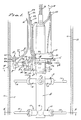
- the casing is shown as a vertically disposed tubular member that is round in cross section, having outer and inner walls 10 and 11.
- the apparatus herein disclosed is designed to be inserted into and lowered in the casing to be cut circumferentially from the interior thereof, as is clearly shown. Accordingly, the apparatus carries a torch T supplied with powdered metal and gases, and under control of means as will now be described.
- the supply of combustible materials can be carried on and by the apparatus as by means of pressure bottles and canisters, or preferably remotely from the surface of the waters as shown.
- the torch cutting apparatus as it is disclosed herein is comprised, generally, of a body B, locating means A for positioning the body, and a carriage and drive means C for advancing the torch T relative to the wall surface to be pre heated and then cut or severed.
- a feature which facilitates insertion and lowering of the apparatus into the casing is a torch positioning means D which is retractile.
- a torch guide means E is Another feature which yields to interfering obstructions such as rust and scale and marine growth.
- This apparatus positions the torch T within the casing at a desired level and then drives the torch around the inner wall 11 thereof and in predetermined spaced relation thereto while supplied with the powdered metal dust and the added oxidizing or cutting agent to effect circumferential cutting of the casing on a continued basis.
- the body B is an elongated vertically disposed member adapted to be inserted into and lowered to a determined depth or level within the casing.
- the body B is a slender tube that is subsequently centered coaxially within the inner casing wall 11, by the locating means A next described.
- the locating means A is at the lower end portion of body B, in which case the carriage and drive means C for carrying the torch T is carried by the body B with the upper end portion of the body accessible for the attachment of gas and hydraulic and electric lines as may be required.
- the body B is a tubular cylinder of relatively small diameter suspended by a cable 12 and having a support for the carriage and drive means C, the support being shown as an upwardly facing shoulder 13.
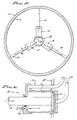
- the locating means A positions the body B on the central axis of the casing, and is comprised of spaced retractile members extended into positioned engagement with the inner wall 11 of the casing.
- the cylinder and piston means 15 and legs 14 combinations are alike, preferably identical, and each involves a cylinder 16 carried by the wall of body B, and a piston 17 reciprocable on an axis radial to the axis of body B.
- the cylinder and piston means 15 is double acting, with the leg 14 connected to the piston 17 and projecting on said radial axis.
- fluid lines 18 communicate with opposite closed and/or sealed ends of the cylinder 16 and enter into the tubular body B so as to extend upwardly therefrom and to and above the water surface (not shown) for the control of operating fluid, preferably hydraulic fluid.
- the control therefor which is not shown, reversably pressures the lines 18 and simultanesouly positions the cylinder and piston means 15, to either extend or retract the same.
- a feature of the cylinder and piston means 15 is an adjustable stop therefor, show as a screw 19 entering the cylinder 16 to limit extension of piston 17 and leg 14, and with a lock nut 20.
- the limited extended positions of the legs 14 is shown in Figs. 1 and 5, whereas the retracted position of the piston 17 and leg 14 is shown in Fig. 6.
- the retracted legs clear obstacles with the casing wall 11.
- the positioning means A can be carried by the upper end portion of body B, so as to be associated with the upper section of casing being severed and removed.
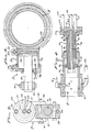
- the carriage and drive means C for advancing the torch T is shown in Figs. 1 and 2, for advancing the torch around the inner casing wall 11.
- the carriage and drive means C is comprised of a collar 21 rotatable on the body B and a motor drive 22 to rotate the collar.
- the collar 21 is positioned by the collar and ring to rotate at a determined height on the body B and has a driven gear 25 meshed with a drive gear 26 revolved by a motor M.
- the motor M is preferably a positive displacement type fluid powered motor for speed control by the rate of fluid flow through lines 27 extending therefrom and to and above the water surface (not shown) for adjustable flow of operating fluid, preferably hydraulic fluid.
- the control means which is not shown, is any state of the art metering device that controls the rate of flow for precise speed operation of motor M and movement of the carriage collar 21.
- the collar 21 is drive continuously through one complete revolution when cutting off a section of casing.
- the motor M is carried by a bracket 28 at the exterior of body B, with the fluid lines 27 accessible as they extend to and above the water surface.
- the torch positioning means D is shown in Figs. 1, 2 and 3, and like means A hereinabove described is a retractile means for extending the torch T into working position.
- the torch positioning means D is comprised of a cylinder and piston means 29 carried by the collar 21 and an adjustment means 30 positioned thereby to carry the torch T.
- the cylinder and piston means 29 is carried by and projects radially from one side of the rotating collar 21 and involves a cylinder 31 and piston 32 reciprocal on a horizontally disposed radial axis from the center of rotation.
- the cylinder and piston means 29 is double acting, with a mounting bar 33 connected to the piston 32 and projecting on said radial axis.
- fluid lines 34 communicate with opposite closed and/or sealed ends of the cylinder 31 and extend upwardly therefrom and to and above the water surface (not shown) for control of operating fluid, preferably hydraulic fluid.
- the control therefor which is not shown, reversably pressures the cylinder and piston means 29, to either extend or retract the same.
- a feature of the cylinder and piston means 29 is an adjustable stop therefor, shown as a screw 35 entering the cylinder 31 to limit extension of piston 32 and mounting bar 33, and with a lock nut 36.
- the limited extended position of the mounting bar 33 is shown in Fig. 1, whereas the retracted position of the piston and bar is shown in Fig. 2. It will be understood that the mounting bar 33 is retracted so as to withdraw the torch T from the inner side wall 11 of the casing to clear obstacles when moving therein.
- the adjustment means 30 for positioning the torch T carries the base of the torch next described, and swivels the torch so that its angular position with respect to wall 11 of the casing can be set as may be required.
- the adjustment means 30 is comprised of a clamp 37 adjustably positioned on the mounting bar 33 to move therewith. Since the mounting bar 33 is essentially a piston rod of round configuration and free to turn, there is a rigid guide rod 38 embraced by a bifurcated portion 39 of clamp 37 to maintain an erect and upright position of said clamp that carries the base of the torch T.
- the swivel of adjustment means 30 for adjusting the torch is best illustrated in Fig.3 and is comprises of a second clamp 40 disposed on a horizontal transverse axis normal to the axis of the mounting bar 33.
- the clamp 40 adjustably rotates on a pin in the form of a bolt 41 with a nut 42 which tightens the second clamp onto the first mentioned clamp 37.
- a typical angle of adjustment when cutting inside vertically disposed casing is approximately 15° as shown in Fig. 1.
- the torch T which is unique with this invention is provided to handle at least two and preferably four separate fluid supplies, in order to practice the powdered metal pre heat and intensified flamecutting method hereinabove described. Accordingly, there are two basic and preferably four fluid supply lines 51 - 54, all accessably extending to and above the water surface and connected to fluid supplies as will now be described.
- Line 51 is connected to a pressure and rate of flow regulated supply means of metal dust admixed with a gas carrier of oxidiser as hereinabove described to establish a pre-heat flame at 1927° to 2760°C (3500° to 5000°F).
- line 53 is connected to a pressure and rate of flow regulated supply of the cutting agent such as oxygen, or hydrogen flouride, or a mixture of the two, as hereinabove described to be added to the above mentioned preheat flame so as to intensify the metal-oxidizer flame and thereby establish a corrosive burning and/or melting through of the steel casing, or other metal and materials that may be invovled.
- the cutting agent is introduced at a fixed point in the center of the preheat flame for an effective cutting effect.
- the third fluid supply line 52 is provided to supply a combustible compressed gas and oxidizer to a pilot means F.
- the fourth fluid supply line 54 is provided to supply a displacement gas such as compressed air to exclude and/or purge surrounding waters from the aforesaid pilot flame F.
- the torch T is comprised of a manifold base 55 and a multi jet nozzle 56.
- the base 55 is secured to the clamp 40 of the torch mounting D and is coupled to the fluid lines 51, 52 and 53, the base having concentric inner and outer forwardly facing channels 61 and 62 in open communicatior with the lines 51 and 52 respectivley, and having a center port 63 in open communication with the line 53.
- the base 55 and nozzle 56 have interface engagement where the channels 61 and 62 and port 63 open forwardly, there being jet passages 71, 72 and 73 through the nozzle to open at the front discharge end thereof.
- the supporting pilot flame is established by outer circumferentially spaced series of jet passages 72 in open communication with the outer channel 62.
- the high temperature preheat flame is established by an inner circumferentially spaced series of jet passages 71 in open communication with the inner channel 61. And, the ultimate cutting flame is established by a central jet passage 73 in open communication with the port 63.
- the arrangement of manifold channels and jet passages is clearly illustrated in Figs 3 and 4, whereby three distinct flames emanate from the nozzle 56; (1) a pilot flame, (2) a preheat flame, and (3) a cutting flame.
- the pilot flame (1) is maintained continuously so as to ignite the preheat flame (2) when required, and the preheat flame is then maintained until the cutting zone is conditioned for cutting.
- the cutting flame (3) is then established by adding the cuting agent so as to made the continuous cut as it is shown started in Fig. 1.
- the torch guide means E and pilot means F operate together to protect the nozzle 56 by shielding the discharge of gases and admixtures hereinabove described.
- a retractile shield 75 of means F slides over the nozzle 56 so as to be extended radially by a spring 76, and stopped by a ring 77.
- a key pin 78 engages a slot 79 in the shield to prevent its rotation, the shield being a forwardly open tube extending from the discharge end of the nozzle 56.
- the extending portion of shield 75 carries a manifold 80 that is coupled to the said fourth fluid supply line 54 to supply the displacement gas such as air, and thereby purge the flame chamber formed thereby ahead of the nozzle.
- the guide means E is shown comprised of a follower 82 in the form of a wheel that rides on the inner wall 11 of the casing, so as to pass over any obstructions such as scale and marine growth.
- the angular position of the follower 82 is adjusted by a clamp 83 having a bolt spaced from and parallel to bolt 41 of adjustment means 30, and set by a nut (not shown).
- the shield 75 retracts on nozzle 56 when the wheel follower 82 passes over inner diameter obstructions, while maintaining a determined spaced relation to said inner wall 11 and any debris theron.
- a spark generating means 90 shown in the form of a plug is exposed through the shield and to the flame chamber within the shield and is powered through an electric cable 91 from above the water surface, to ignite the pre heat flame and/or the pilot flame.
- the apparatus disclosed herein is especially adapted to cut from the interior of casing and the like, and is operated entirely remote and above the water surface to supply gas, gas admixture with metal powders, and fluid and electric power sources.
- a pilot flame and/or spark ignition means is provided for initiating the preheat flame, said preheat flame being a high heat powdered metal and gas flame for rapid conditioning of the cutting zone, and to which the cutting agent is added for cutting.
Landscapes
- Engineering & Computer Science (AREA)
- Mechanical Engineering (AREA)
- Chemical & Material Sciences (AREA)
- Combustion & Propulsion (AREA)
- General Engineering & Computer Science (AREA)
- Arc Welding In General (AREA)
Claims (28)
- Procédé de découpe de parois métalliques et analogues sous l'eau, et comprenant une première étape de préchauffage d'une zone de découpe sur la paroi (10, 11) avec une flamme de préchauffage ayant une puissance calorique pour atteindre une température de préchauffage dans ladite zone de découpe, et une seconde étape d'adjonction d'un agent de découpe apporteur de calories dans la flamme de préchauffage pour augmenter la puissance calorique de la flamme de préchauffage, caractérisé en ce que l'on préchauffe la zone de découpe sur la paroi (10, 11) avec une flamme de préchauffage comprenant de la poudre métallique dans un support de gaz oxydant, et l'on amène l'agent de découpe apporteur de calories à brûler la poudre métallique à une température plus élevée avec la paroi métallique (10, 11) de la zone de découpe et à traverser cette dernière par brûlage.
- Procédé de découpe par brûlage de parois métalliques sous l'eau selon la revendication 1, caractérisé en ce que la poudre métallique comprend l'un quelconque des métaux magnésium, fer et aluminium, ou une combinaison de ces derniers, sous forme pulvérulente, portée par ledit gaz oxydant.
- Procédé de découpe par brûlage de parois métalliques sous l'eau tel selon la revendication 1 ou la revendication 2, caractérisé en ce que l'agent de découpe apporteur de calories est l'oxygène, ou le fluorure d'hydrogène ou un mélange des deux.
- Procédé de découpe par brûlage de parois métalliques sous l'eau tel selon les revendications 1 à 3, caractérisé en ce que la température de la flamme de préchauffage est située dans l'intervalle de 1.927°C à 2.760°C (3.500°F à 5.000°F).
- Procédé de découpe par brûlage de parois métalliques sous l'eau selon l'une quelconque des revendications 1 à 4, caractérisé en ce que la seconde étape de brûlage dépasse 2.760°C (5.000°F).
- Procédé de découpe par brûlage de parois métalliques sous l'eau selon l'une quelconque des revendications 1 à 5, caractérisé en ce que la poudre métallique est une poudre de configuration en paillettes.
- Procédé de découpe par brûlage de parois métalliques sous l'eau selon l'une quelconque des revendications 1 à 5, caractérisé en ce que la poudre de métal est une poudre de configuration sphérique atomisée.
- Procédé de découpe par brûlage de parois métalliques sous l'eau selon l'une quelconque des revendications 1 à 7, caractérisé en ce que la poudre métallique a une granulométrie de 100 à 300 microns.
- Appareil pour mettre en oeuvre le procédé selon la revendication 1, comprenant: une lance (56) ayant au moins deux connexions (51, 53) de fluide sur elle, caractérisé en ce que la lance (56) a une première connexion (51) pour une poudre métallique mélangée avec un oxydant gazeux, et une seconde connexion (53) pour un agent gazeux de découpe, et ayant un passage (71, 73) de jet pour chacune desdites connexions et s'ouvrant à une extrémité frontale de décharge de la lance (56), un moyen (A) situant l'extrémité de décharge de la lance en position d'espacement par rapport à la paroi métallique (10, 11) à découper, un moyen fournissant le mélange de poudre métallique et d'oxydant gazeux à la première connexion (51) pour être déchargé depuis ledit passage (71) de jet dans ce but, et pour l'ignition afin de créer une flamme de préchauffage à haute température en une zone de découpe de la paroi métallique (10, 11), et un moyen fournissant l'agent gazeux de découpe à la seconde connexion (53) pour être déchargé depuis ledit passage (73) de jet dans ce but, afin d'intensifier la flamme de préchauffage mentionnée ci-dessus, et ainsi découper, en la traversant, la paroi métallique (10, 11) par brûlage et fusion.
- Appareil selon la revendication 9, caractérisé en ce qu'il comporte un moyen (c) d'entraînement pour avancer la lance au-dessus de la paroi métallique (10, 11).
- Appareil selon la revendication 10, caractérisé en ce que ledit moyen (c) d'entraînement comprend un moteur (m) actionné par un déplacement positif de fluide, sensible à un dispositif de mesure de débit d'écoulement pour la vitesse précise d'avancement de la lance (56) au-dessus de la paroi métallique (10, 11).
- Appareil selon les revendications 9, 10 et 11, caractérisé en ce que la lance a une série de passages (71) de jet espacés de façon circonférentielle, pour la décharge en cet endroit du mélange de poudre métallique et de l'oxydant depuis la première connexion (51), et a un passage central (73) de jet pour la décharge en cet endroit de l'agent gazeux de découpe depuis la seconde connexion (53).
- Appareil selon les revendications 9 à 12, caractérisé en ce que le moyen (A) situant l'extrémité de décharge de la lance (56) est composé de pièces rétractiles (14, 15), étendues en engagement de positionnement avec la paroi métallique (10, 11) pour maintenir la lance (56) dans ladite relation d'espacement par rapport à la paroi métallique à découper.
- Appareil selon les revendications 9 à 13, caractérisé en ce que le moyen fournissant la poudre métallique et l'oxydant gazeux est un moyen de pression et de débit d'écoulement, fournissant un mélange de poudre métallique dont la granulométrie va de 100 à 300 microns, et avec un taux sensiblement de 1,067 kg/m³ d'oxydant gazeux.
- Appareil selon les revendications 10 à 14, caractérisé en ce que le moyen fournissant l'agent gazeux de découpe est un moyen de pression et de débit d'écoulement.
- Appareil selon les revendications 10 à 15, et comportant une troisième connexion (52) pour un gaz combustible et un oxydant, et ayant un passage (72) de jet pour ladite connexion (52) et s'ouvrant sur l'extrémité frontale de la lance, et un moyen pour fournir le gaz combustible et l'oxydant à la troisième connexion (52) pour être déchargé depuis ledit passage de jet dans ce but, pour l'ignition afin de créer une flamme pilote pour l'ignition de la flamme de préchauffage à haute température.
- Appareil selon la revendication 16, caractérisé en ce que la lance (56) a au moins deux séries concentriques de passages (71, 72) de jet espacés de façon circonférentielle, l'une pour la décharge du mélange de la poudre métallique et de l'oxydant depuis la première connexion (51) à cet endroit, et l'autre pour la décharge du gaz combustible et de l'oxydant depuis la troisième connexion (52) à cet endroit, et a un passage central (73) de jet pour la décharge de l'agent gazeux de découpe depuis la seconde connexion (53) à cet endroit.
- Appareil selon l'une quelconque des revendications précédentes 9 à 17 pour la découpe de parois d'enveloppes métalliques tubulaires, caractérisé par un corps (B) à insérer dans l'enveloppe (10, 11) métallique tubulaire et ayant un axe central, un moyen (C) de support et d'entraînement pour une rotation autour de l'axe central du corps (B) et à l'intérieur de la paroi (10, 11) d'enveloppe métallique tubulaire, ladite lance (56) étant supportée par l'axe central du corps (B) et le moyen de support, et disposée radialement par rapport à cet axe, et le moyen (A) situant l'axe central du corps de façon concentrique par rapport à l'axe central de l'enveloppe métallique tubulaire, et avec l'extrémité de décharge de la lance (56) en relation d'espacement par rapport à la paroi (11) du diamètre intérieur de l'enveloppe de métal tubulaire.
- Appareil selon la revendication 18, caractérisé par un moyen (12) pour suspendre le corps (B) à l'intérieur de l'enveloppe (10, 11) métallique tubulaire.
- Appareil selon les revendications 18 et 19, caractérisé en ce que le moyen de support est de la forme d'un collier (21) libre de tourner sur le corps (B), et le moyen (C) d'entraînement est un moteur (M) qui fait tourner le collier.
- Appareil selon les revendications 18, 19 et 20 caractérisé en ce qu'un moyen (D) pour situer l'extrémité de décharge de la lance étend la lance (56) depuis le moyen de support (21) et le moyen (C) d'entraînement, et dans une position prédéterminée quand le moyen (A), situant l'axe central du corps (B) est activé pour centrer ce dernier.
- Appareil selon la revendication 21, caractérisé en ce que le moyen (D) pour situer l'extrémité de décharge de la lance est un moyen (29) à cylindre et piston disposé sur un axe radial par rapport à l'axe central du corps (B) et du support (21).
- Appareil selon l'une quelconque des revendications 9 à 22, caractérisé par un écran (75) qui entoure l'extrémité frontale de la lance (56) et s'étend depuis cette extrémité, pour former une chambre de flamme séparée des eaux avoisinantes.
- Appareil selon la revendication 23, caractérisé en ce que ledit écran (75) est rétractile et est décalé en relation d'espacement par rapport à la paroi (11) du diamètre intérieur de l'enveloppe (10, 11) métallique tubulaire, par un moyen (76) de ressort limité par une butée (77).
- Appareil selon la revendication 24, caractérisé en ce que ledit écran (75) est pourvu d'une roue suiveuse (82) pouvant être en contact avec la paroi (11) du diamètre intérieur de l'enveloppe (10, 11) métallique tubulaire.
- Appareil selon les revendications 23, 24 et 25, caractérisé en ce que l'écran (75) a une quatrième connexion (54) de fluide et au moins une ouverture (80) de jet dans la chambre de flamme, pour purger la chambre avec de l'air en provenance d'un moyen de fourniture d'air en cet endroit.
- Appareil selon les revendications 18 à 26 caractérisé en ce que le moyen (A) pour situer l'axe central du corps (B) de façon concentrique par rapport à l'axe central de l'enveloppe (10, 11) métallique tubulaire comprend des ensembles de jambages rétractiles (14) espacés longitudinalement et disposés radialement, qui s'étendent par un moyen (16) en position d'engagement avec la paroi (11) du diamètre intérieur de l'enveloppe (10, 11) métallique tubulaire.
- Appareil selon la revendication 27, caractérisé en ce que chaque ensemble de jambages (14) comprend trois jambages rétractiles (14) et disposés radialement, qui s'étendent par un moyen (16) de cylindre et piston en position d'engagement avec la paroi (11) du diamètre intérieur de l'enveloppe (10, 11) métallique tubulaire.
Applications Claiming Priority (2)
| Application Number | Priority Date | Filing Date | Title |
|---|---|---|---|
| US124584 | 1987-11-24 | ||
| US07/124,584 US4790886A (en) | 1987-11-24 | 1987-11-24 | Method and apparatus for remote under water torch cutting |
Publications (3)
| Publication Number | Publication Date |
|---|---|
| EP0318153A2 EP0318153A2 (fr) | 1989-05-31 |
| EP0318153A3 EP0318153A3 (en) | 1989-08-30 |
| EP0318153B1 true EP0318153B1 (fr) | 1992-09-02 |
Family
ID=22415724
Family Applications (1)
| Application Number | Title | Priority Date | Filing Date |
|---|---|---|---|
| EP88309942A Expired EP0318153B1 (fr) | 1987-11-24 | 1988-10-21 | Méthode et appareil pour le découpage à la torche sous l'eau à distance |
Country Status (3)
| Country | Link |
|---|---|
| US (1) | US4790886A (fr) |
| EP (1) | EP0318153B1 (fr) |
| DE (1) | DE3874295T2 (fr) |
Families Citing this family (9)
| Publication number | Priority date | Publication date | Assignee | Title |
|---|---|---|---|---|
| EP0444974A1 (fr) * | 1990-02-01 | 1991-09-04 | Gaz De France | Procédé et dispositif de remplacement d'une canalisation enterrée |
| FR2657674B1 (fr) * | 1990-02-01 | 1993-06-18 | Gaz De France | Procede et dispositif de remplacement d'une canalisation enterree. |
| DE4033618A1 (de) * | 1990-10-23 | 1992-04-30 | Messer Griesheim Gmbh | Verfahren zum unterwasserschneiden |
| EP2703564B1 (fr) * | 2012-08-30 | 2016-04-27 | BAUER Maschinen GmbH | Cadre de guidage pour guider un dispositif de fraisage |
| CN108115245A (zh) * | 2018-01-04 | 2018-06-05 | 上海宝业机电科技有限公司 | 一种小口径管内切割机 |
| CN111250818B (zh) * | 2020-04-15 | 2021-08-20 | 宁波宏诺汽车零部件科技有限公司 | 一种智能高效的盘管管端切削机构 |
| CN114046498B (zh) * | 2021-09-30 | 2023-07-28 | 北京动力机械研究所 | 焰色添色型水下火炬 |
| CN114034042B (zh) * | 2021-09-30 | 2023-07-28 | 北京动力机械研究所 | 一种稳燃型水下火炬燃烧控制方法 |
| CN116460401B (zh) * | 2022-01-11 | 2026-04-07 | 中国石油天然气集团有限公司 | 热熔式连续油管切割装置 |
Family Cites Families (7)
| Publication number | Priority date | Publication date | Assignee | Title |
|---|---|---|---|---|
| FR837791A (fr) * | 1937-06-11 | 1939-02-20 | Linde Air Prod Co | Procédé et appareil pour la mise en train d'un ébarbage, ou écroutage, d'un découpage ou d'un usinage à la flamme, de pièces métalliques |
| US2286191A (en) * | 1939-04-18 | 1942-06-16 | Linde Air Prod Co | Mineral piercing and cutting |
| US2286192A (en) * | 1939-04-18 | 1942-06-16 | Linde Air Prod Co | Mineral piercing and cutting |
| US2664368A (en) * | 1951-06-06 | 1953-12-29 | Union Carbide & Carbon Corp | External powder feed scarfing process and apparatus |
| US2855337A (en) * | 1956-05-01 | 1958-10-07 | Edward M Holub | Method of and adjuvant powder for thermochemical material removal from refractory materials |
| US2975002A (en) * | 1960-03-14 | 1961-03-14 | Reynolds Metals Co | Blow torch feeder control |
| US4115154A (en) * | 1977-09-26 | 1978-09-19 | Union Carbide Corporation | Method and apparatus for producing a post-mixed, stabilized scarfing pre-heating flame |
-
1987
- 1987-11-24 US US07/124,584 patent/US4790886A/en not_active Expired - Fee Related
-
1988
- 1988-10-21 EP EP88309942A patent/EP0318153B1/fr not_active Expired
- 1988-10-21 DE DE8888309942T patent/DE3874295T2/de not_active Expired - Lifetime
Also Published As
| Publication number | Publication date |
|---|---|
| EP0318153A2 (fr) | 1989-05-31 |
| DE3874295T2 (de) | 1992-12-24 |
| US4790886A (en) | 1988-12-13 |
| DE3874295D1 (de) | 1992-10-08 |
| EP0318153A3 (en) | 1989-08-30 |
Similar Documents
| Publication | Publication Date | Title |
|---|---|---|
| CA1146065A (fr) | Methode et dispositif de sectionnement de canalisations | |
| EP0318153B1 (fr) | Méthode et appareil pour le découpage à la torche sous l'eau à distance | |
| US5207533A (en) | Process and device for replacing an underground pipe | |
| US7739968B2 (en) | System, apparatus and method for combustion of metals and other fuels | |
| US3507230A (en) | Method and tool for cutting by deflagration dense materials | |
| NZ200837A (en) | Underground gasification of coal | |
| US2327496A (en) | Method of and apparatus for working mineral materials and the like | |
| US2327482A (en) | Mineral cutting and piercing | |
| US3045766A (en) | Suspension type rotary piercing process and apparatus | |
| CA3140293A1 (fr) | Outil de fond de trou a systeme d'alimentation | |
| US12312889B2 (en) | Tool for manipulating a target with combustion products | |
| US5159983A (en) | Apparatus and method for capping oil or gas wells | |
| USRE22964E (en) | Method of and apparatus for work | |
| US20170350206A1 (en) | Method of removing materials by their disintegration by action of electric plasma | |
| CN100430171C (zh) | 热力去除割缝油井衬管的毛刺的装置和方法 | |
| US3066058A (en) | Chemical cutting and working | |
| RU2042483C1 (ru) | Устройство для газовой резки твердых материалов | |
| CN209902462U (zh) | 一种便携式安全焊笔 | |
| DE10103214B4 (de) | Verfahren und Vorrichtung zur Reinigung von Oberflächen in Hohlräumen | |
| US3034874A (en) | Blow torch fuel and method of burning same | |
| US3128824A (en) | Chemical cutting and working | |
| SU1562601A1 (ru) | Газова горелка | |
| GB550683A (en) | Improvements in the working of mineral or mineral-like bodies | |
| EP3837420B1 (fr) | Outil amélioré pour manipuler un objet | |
| RU2069815C1 (ru) | Газовоздушная горелка со сверхзвуковой струей |
Legal Events
| Date | Code | Title | Description |
|---|---|---|---|
| PUAI | Public reference made under article 153(3) epc to a published international application that has entered the european phase |
Free format text: ORIGINAL CODE: 0009012 |
|
| AK | Designated contracting states |
Kind code of ref document: A2 Designated state(s): BE DE ES FR GB GR IT LU NL |
|
| PUAL | Search report despatched |
Free format text: ORIGINAL CODE: 0009013 |
|
| AK | Designated contracting states |
Kind code of ref document: A3 Designated state(s): BE DE ES FR GB GR IT LU NL |
|
| 17P | Request for examination filed |
Effective date: 19890927 |
|
| 17Q | First examination report despatched |
Effective date: 19901122 |
|
| GRAA | (expected) grant |
Free format text: ORIGINAL CODE: 0009210 |
|
| AK | Designated contracting states |
Kind code of ref document: B1 Designated state(s): BE DE ES FR GB GR IT LU NL |
|
| PG25 | Lapsed in a contracting state [announced via postgrant information from national office to epo] |
Ref country code: IT Free format text: LAPSE BECAUSE OF FAILURE TO SUBMIT A TRANSLATION OF THE DESCRIPTION OR TO PAY THE FEE WITHIN THE PRE;WARNING: LAPSES OF ITALIAN PATENTS WITH EFFECTIVE DATE BEFORE 2007 MAY HAVE OCCURRED AT ANY TIME BEFORE 2007. THE CORRECT EFFECTIVE DATE MAY BE DIFFERENT FROM THE ONE RECORDED.SCRIBED TIME-LIMIT Effective date: 19920902 Ref country code: GR Free format text: LAPSE BECAUSE OF FAILURE TO SUBMIT A TRANSLATION OF THE DESCRIPTION OR TO PAY THE FEE WITHIN THE PRESCRIBED TIME-LIMIT Effective date: 19920902 Ref country code: ES Free format text: THE PATENT HAS BEEN ANNULLED BY A DECISION OF A NATIONAL AUTHORITY Effective date: 19920902 Ref country code: BE Effective date: 19920902 |
|
| REF | Corresponds to: |
Ref document number: 3874295 Country of ref document: DE Date of ref document: 19921008 |
|
| ET | Fr: translation filed | ||
| PG25 | Lapsed in a contracting state [announced via postgrant information from national office to epo] |
Ref country code: LU Free format text: LAPSE BECAUSE OF NON-PAYMENT OF DUE FEES Effective date: 19921031 |
|
| PG25 | Lapsed in a contracting state [announced via postgrant information from national office to epo] |
Ref country code: NL Effective date: 19930501 |
|
| NLV4 | Nl: lapsed or anulled due to non-payment of the annual fee | ||
| PG25 | Lapsed in a contracting state [announced via postgrant information from national office to epo] |
Ref country code: DE Effective date: 19930701 |
|
| PLBE | No opposition filed within time limit |
Free format text: ORIGINAL CODE: 0009261 |
|
| STAA | Information on the status of an ep patent application or granted ep patent |
Free format text: STATUS: NO OPPOSITION FILED WITHIN TIME LIMIT |
|
| 26N | No opposition filed | ||
| PG25 | Lapsed in a contracting state [announced via postgrant information from national office to epo] |
Ref country code: FR Effective date: 19930831 |
|
| REG | Reference to a national code |
Ref country code: FR Ref legal event code: ST |
|
| PGFP | Annual fee paid to national office [announced via postgrant information from national office to epo] |
Ref country code: GB Payment date: 19981001 Year of fee payment: 11 |
|
| PG25 | Lapsed in a contracting state [announced via postgrant information from national office to epo] |
Ref country code: GB Free format text: LAPSE BECAUSE OF NON-PAYMENT OF DUE FEES Effective date: 19991021 |
|
| GBPC | Gb: european patent ceased through non-payment of renewal fee |
Effective date: 19991021 |
|
| PG25 | Lapsed in a contracting state [announced via postgrant information from national office to epo] |
Ref country code: FR Effective date: 19921031 |