EP0318180A1 - Elektrischer Verbinder mit Schutz gegen hohen Stromstoss - Google Patents
Elektrischer Verbinder mit Schutz gegen hohen Stromstoss Download PDFInfo
- Publication number
- EP0318180A1 EP0318180A1 EP88310557A EP88310557A EP0318180A1 EP 0318180 A1 EP0318180 A1 EP 0318180A1 EP 88310557 A EP88310557 A EP 88310557A EP 88310557 A EP88310557 A EP 88310557A EP 0318180 A1 EP0318180 A1 EP 0318180A1
- Authority
- EP
- European Patent Office
- Prior art keywords
- receptacle
- plug
- conductive
- electrical
- contact
- Prior art date
- Legal status (The legal status is an assumption and is not a legal conclusion. Google has not performed a legal analysis and makes no representation as to the accuracy of the status listed.)
- Granted
Links
- 239000000463 material Substances 0.000 claims abstract description 28
- 239000002131 composite material Substances 0.000 claims abstract description 18
- 239000004020 conductor Substances 0.000 claims description 18
- 230000008878 coupling Effects 0.000 claims description 12
- 238000010168 coupling process Methods 0.000 claims description 12
- 238000005859 coupling reaction Methods 0.000 claims description 12
- 238000007747 plating Methods 0.000 claims description 10
- 230000007797 corrosion Effects 0.000 claims description 7
- 238000005260 corrosion Methods 0.000 claims description 7
- 229910052751 metal Inorganic materials 0.000 claims description 2
- 239000002184 metal Substances 0.000 claims description 2
- 239000007769 metal material Substances 0.000 claims 3
- PXHVJJICTQNCMI-UHFFFAOYSA-N Nickel Chemical compound [Ni] PXHVJJICTQNCMI-UHFFFAOYSA-N 0.000 description 4
- 230000008901 benefit Effects 0.000 description 4
- 230000006378 damage Effects 0.000 description 4
- 230000009471 action Effects 0.000 description 3
- 239000000835 fiber Substances 0.000 description 3
- 238000007792 addition Methods 0.000 description 2
- 239000011230 binding agent Substances 0.000 description 2
- 230000005540 biological transmission Effects 0.000 description 2
- 238000004891 communication Methods 0.000 description 2
- 230000006854 communication Effects 0.000 description 2
- 230000000694 effects Effects 0.000 description 2
- PCHJSUWPFVWCPO-UHFFFAOYSA-N gold Chemical compound [Au] PCHJSUWPFVWCPO-UHFFFAOYSA-N 0.000 description 2
- 229910052737 gold Inorganic materials 0.000 description 2
- 239000010931 gold Substances 0.000 description 2
- 238000000034 method Methods 0.000 description 2
- 239000000203 mixture Substances 0.000 description 2
- 229910052759 nickel Inorganic materials 0.000 description 2
- 239000012811 non-conductive material Substances 0.000 description 2
- 229910052709 silver Inorganic materials 0.000 description 2
- 239000004332 silver Substances 0.000 description 2
- 230000000153 supplemental effect Effects 0.000 description 2
- OKTJSMMVPCPJKN-UHFFFAOYSA-N Carbon Chemical compound [C] OKTJSMMVPCPJKN-UHFFFAOYSA-N 0.000 description 1
- 229920000049 Carbon (fiber) Polymers 0.000 description 1
- 229910000881 Cu alloy Inorganic materials 0.000 description 1
- 239000004593 Epoxy Substances 0.000 description 1
- 238000005299 abrasion Methods 0.000 description 1
- 239000000853 adhesive Substances 0.000 description 1
- 230000001070 adhesive effect Effects 0.000 description 1
- 230000002411 adverse Effects 0.000 description 1
- 229910045601 alloy Inorganic materials 0.000 description 1
- 239000000956 alloy Substances 0.000 description 1
- 229910052782 aluminium Inorganic materials 0.000 description 1
- XAGFODPZIPBFFR-UHFFFAOYSA-N aluminium Chemical compound [Al] XAGFODPZIPBFFR-UHFFFAOYSA-N 0.000 description 1
- 229910052799 carbon Inorganic materials 0.000 description 1
- 239000004917 carbon fiber Substances 0.000 description 1
- 239000000356 contaminant Substances 0.000 description 1
- 230000001808 coupling effect Effects 0.000 description 1
- 238000012217 deletion Methods 0.000 description 1
- 230000037430 deletion Effects 0.000 description 1
- 238000013461 design Methods 0.000 description 1
- 238000004880 explosion Methods 0.000 description 1
- 230000002401 inhibitory effect Effects 0.000 description 1
- 238000003780 insertion Methods 0.000 description 1
- 230000037431 insertion Effects 0.000 description 1
- 238000009434 installation Methods 0.000 description 1
- 238000004519 manufacturing process Methods 0.000 description 1
- 230000013011 mating Effects 0.000 description 1
- 238000012986 modification Methods 0.000 description 1
- 230000004048 modification Effects 0.000 description 1
- 238000009877 rendering Methods 0.000 description 1
- 230000035939 shock Effects 0.000 description 1
- 239000010935 stainless steel Substances 0.000 description 1
- 229910001220 stainless steel Inorganic materials 0.000 description 1
- 239000000126 substance Substances 0.000 description 1
Images


Classifications
-
- H—ELECTRICITY
- H01—ELECTRIC ELEMENTS
- H01R—ELECTRICALLY-CONDUCTIVE CONNECTIONS; STRUCTURAL ASSOCIATIONS OF A PLURALITY OF MUTUALLY-INSULATED ELECTRICAL CONNECTING ELEMENTS; COUPLING DEVICES; CURRENT COLLECTORS
- H01R13/00—Details of coupling devices of the kinds covered by groups H01R12/70 or H01R24/00 - H01R33/00
- H01R13/648—Protective earth or shield arrangements on coupling devices, e.g. anti-static shielding
- H01R13/658—High frequency shielding arrangements, e.g. against EMI [Electro-Magnetic Interference] or EMP [Electro-Magnetic Pulse]
- H01R13/6581—Shield structure
- H01R13/6582—Shield structure with resilient means for engaging mating connector
- H01R13/6583—Shield structure with resilient means for engaging mating connector with separate conductive resilient members between mating shield members
- H01R13/6584—Shield structure with resilient means for engaging mating connector with separate conductive resilient members between mating shield members formed by conductive elastomeric members, e.g. flat gaskets or O-rings
-
- H—ELECTRICITY
- H01—ELECTRIC ELEMENTS
- H01R—ELECTRICALLY-CONDUCTIVE CONNECTIONS; STRUCTURAL ASSOCIATIONS OF A PLURALITY OF MUTUALLY-INSULATED ELECTRICAL CONNECTING ELEMENTS; COUPLING DEVICES; CURRENT COLLECTORS
- H01R13/00—Details of coupling devices of the kinds covered by groups H01R12/70 or H01R24/00 - H01R33/00
- H01R13/648—Protective earth or shield arrangements on coupling devices, e.g. anti-static shielding
- H01R13/658—High frequency shielding arrangements, e.g. against EMI [Electro-Magnetic Interference] or EMP [Electro-Magnetic Pulse]
- H01R13/6591—Specific features or arrangements of connection of shield to conductive members
- H01R13/6592—Specific features or arrangements of connection of shield to conductive members the conductive member being a shielded cable
-
- Y—GENERAL TAGGING OF NEW TECHNOLOGICAL DEVELOPMENTS; GENERAL TAGGING OF CROSS-SECTIONAL TECHNOLOGIES SPANNING OVER SEVERAL SECTIONS OF THE IPC; TECHNICAL SUBJECTS COVERED BY FORMER USPC CROSS-REFERENCE ART COLLECTIONS [XRACs] AND DIGESTS
- Y10—TECHNICAL SUBJECTS COVERED BY FORMER USPC
- Y10S—TECHNICAL SUBJECTS COVERED BY FORMER USPC CROSS-REFERENCE ART COLLECTIONS [XRACs] AND DIGESTS
- Y10S439/00—Electrical connectors
- Y10S439/939—Electrical connectors with grounding to metal mounting panel
Definitions
- This invention relates generally to the field of electrical connectors, and more particularly to apparatus and method for providing electrical connectors made of low conductive and/or nonconductive materials, such as composite, with protection against relatively high current electrical surges produced by natural phenomena such as lightning, and various man-made phenomena, such as EMP.
- One form of electrical connector includes a plug portion and a receptacle portion.
- Each of the plug and receptacle portions includes an insulative insert carrying one or more electrical contacts. When the plug and receptacle are mated, or engaged, the electrical contacts are engaged to complete an electrical circuit.
- the plug portion comprises a generally barrel-shaped plug body.
- the receptacle portion comprises a cylindrical receptacle body having an outer wall defined by inside and outside diameters, the inside diameter of the wall defining a receptacle cavity to facilitate the removable insertion and engagement therein of the plug body as generally described above.
- Connectors of the type described are frequently used to longitudinally couple together sections of jacketed cable incorporating one or more interior conductors and an outer conductor jacket which is desirably grounded.
- One of the functions of the grounded outer jacket is to facilitate the harmless grounding of short duration, large current impulses, such as resulting from lightning strikes, which may occur along the cable, or along other HF, VHF or UHF transmission lines.
- Such surges if not properly grounded, can damage equipment, such as communication and control equipment, to which the cable is connected.
- EMP Electro-magnetic Pulse
- Vulnerability of sensitive electronic gear to both natural and man made surge phenomena has been exacerbated in recent years by the increasing use of composite, plastic and other low conductive materials for structural components in such military hardware as helicopters, war planes, ground transport equipment and other items.
- the outer jackets of adjacent longitudinally coupled sections of cable be electrically conductively coupled together.
- Such electrical coupling of sections along the entire transmission line path facilitates the provision of adequate grounding means by the use of a single grounding terminal, or by a relatively few such terminals. If the jackets are not electrically conductively coupled together, then each section of jacketing would require its own ground, increasing the cost and complexity of the equipment.
- Connector parts such as plugs and receptacles
- Connector parts have been made from many different materials.
- metallic connector part bodies have been used. These possess the inherent advantage of electrical conductivity rendering the electrical coupling of jacketing of adjacent sections of cable an easy matter. Because of the tendency of metallic parts to corrode, however, use of such parts is not feasible in corrosive environments, or such use makes necessary the addition of expensive and wear sensitive corrosion-inhibiting plating.
- an electrical conductor apparatus including a plug barrel member and a receptacle member.
- the plug barrel defines an outer wall.
- the receptacle has an external wall portion which defines a receptacle cavity suitable for accommodating engagement of the plug barrel member.
- the receptacle wall is defined by outward and inward facing surfaces.
- Each of the plug barrel and receptacle is chiefly made of a low electrically conductive or insulative material.
- Current carrying capacity is provided to the members by first and second conductive elements of material extending generally longitudinally with respect to the plug and receptacle parts.
- Each conductive element terminates in a contact region which mates in a wiping contact action with the contact region of the other element when the plug and receptacle are engaged.
- the conductive elements are connected at their remote ends to the outer jacket portion of respective adjacent sections of cable, providing good conductive coupling between the jacket portions of the cable to facilitate efficient grounding of high current electrical surges which may occur due to undesirable phenomena.
- each conductive element is made of a strip of metallic conductive material, such as copper alloy, gold or silver, having a cross sectional dimension sufficient to provide low enough resistance for the efficient handling of relatively high current short duration electrical surges.
- a resistance of about 2.0 milliohms or less is desirable.
- the contact regions define a curved configuration, each extending in convex fashion toward the other to define a resilient coupling action when the receptacle and plug are engaged.
- Such resilient coupling results in a desirable wiping action during establishment of contact. It also inhibits inadvertent loss of contact as a result of shock or vibration.
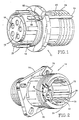
- the plug barrel comprises a generally cylindrical plug body portion 14 which is made of a composite material having relatively low electrical conductivity. Inserted in the plug body 14 is an insulative member 16 which defines the location of, and supports, electrical contacts such as at 18.
- the receptacle 12 includes a receptacle body portion 20 made of a composite material similar to that used for the plug body portion 14.
- the receptacle body 20 defines a generally hollow cylindrical configuration defined by a wall 22 having an outward facing surface 24 and an inward facing surface 26.
- the plug and receptacle body portions can be made of substantially insulative plastic material as well as composite materials.
- composite is meant a substance including a binder or adhesive material, such as epoxy, impregnated with fibers.
- the fibers can be of either nonconductive or conductive materials. Where conductive fibers are used, the composite material, while not having good electrical conductivity, possesses electrical conductivity at a low level. This low level of electrical conductivity can be useful for shielding effects, but is not sufficient to handle high current surges such as are discussed in this document.
- Examples of conductive composites are those comprising mixtures of binder material and aluminum flakes, stainless steel, or carbon. Mixtures of nickel coated carbon fibers are also useful.
- plug and receptacle are depicted in the drawings as having circular cross-section, the parts are not so limited in design and can have other cross-sectional geometry such as rectangular, oval, etc.
- Keyways such as 28 are defined on the inward facing surface 26 of the wall 22 for matching alignment by keys such as 30 (Figure 1) on the plug barrel.
- Another insulative contact mounting structure 31, of known type is located within the cavity defined by the inward facing surface 26 of the receptacle wall 22.
- This insulative structure defines the location of and supports electrical contacts which are aligned for mating engagement with the contacts such as 18 supported by the insulative structure 16 in the plug barrel when the plug barrel is inserted into the receptacle such that the keys 30 are aligned with the respective keyways 28 on the receptacle.
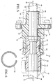
- the electrical contacts 18 are conductively coupled in known fashion through the plug barrel to a section of jacketed cable, shown in phantom at 32, extending to the right of the plug barrel as illustrated in Figure 4.
- the jacketed cable includes one or more interior conductors such as 34 and an outer conductive jacket 36.
- FIG. 4 Also illustrated in Figure 4, in phantom, is a known coupling device 40 for securing the cable to the right hand end of the plug barrel by means of a threaded portion 42.
- FIG. 3 another section of jacketed cable 44, shown in phantom, including one or more central or interior conductors such as 46 and an outer conductive jacket 48, is secured to the left hand end of the receptacle, as shown in Figure 3, by means of a known coupling device 50, also shown in phantom.
- the interior conductors of the cable 44 are electrically coupled to electrical contacts in the receptacle cavity in a position at which, when plug and receptacle are engaged the interior conductors of the cable section 32 are electrically coupled to the interior conductors of the cable section 44.
- the coupling member 50 secures the cable 44 to the left hand end of the receptacle as shown in Figure 3 by means of a threaded portion 52 defined on the outer surface of the receptacle.
- An important feature of this invention is the provision of this means for effecting this electrical coupling between jacket portions of cable secured to the plug barrel and to the receptacle, respectively.
- this conductive means is embodied in part by a first conductive element 60 extending generally longitudinally with respect to the plug barrel.
- the conductive portion 60 includes a tongue portion generally indicated at 62, near the right hand end of the plug barrel as shown in Figure 1, and which terminates in an end section 64.
- the end section 64 is conductively coupled in known fashion to the outer jacket portion 36 of the cable section 32.
- the left hand end of the conductive element 60 terminates in a portion 66 which defines a first contact region. See also Figure 9.
- the first contact region 66 is adapted to engage a second conductive element attached to the receptacle portion, which part will be described in more detail below.
- the receptacle includes a flange portion 74.
- the conductive element 70 may emerge from the composite material and, in a section designated generally as 76, defines a conductive path around the outer edge of the flange 74.
- the element 70 On the opposite side of the flange 74, i.e., to the left as shown in Figure 3, the element 70, over a section 78, again becomes recessed within the composite material making up the receptacle, until terminating in exposed region 80, which is suitable for electrically conductive coupling to the jacket portion of the cable 44.
- An advantage of the conductive element running about the outside of the receptacle, such as around the flange as discussed above, is that the exposed nature of the conductive element facilitates grounding of the conductive element and hence of the jacket portions of the jacketed cables.
- the conductive element such as 60 or 70 can be substantially embedded in the material from which the body of the receptacle or plug barrel is made. In fact, manufacturing costs are minimized where substantially the entire elongated conductive element is embedded or buried in the body part material, leaving only small contact points exposed at either end.
- Figure 5 illustrates a plug and receptacle, with their associated conductive elements 60, 70, in mated, or engaged, relation.
- the respective contact regions 66, 72 are configured with a curvature which, when the elements 60, 70 are engaged, extends the contact regions toward one another, to provide resilient pressure tending to keep the contact areas in electrically conductive contact.
- Such resilient pressure provides a desirable wiping action which, during engagement and disengagement, tends to beneficially affect the contact areas by wiping away oxides and other contaminants which might otherwise tend to interfere with good electrically conductive contact.
- the resilient contact pressure also helps to prevent inadvertent decoupling in the presence of vibration.
- the elements 60, 70 are made of electrically conductive metallic strip material. More specifically, the material is BeCu 25 alloy.
- the elongated conductive elements 60, 70 are made of a material and have a cross sectional size and length such that their total resistance is about 2.0 milliohms or less.
- the cross sectional geometry and area can be adjusted in accordance with the length of the conductive element and the material from which it is made in order to implement the desired total resistance.
- the elongated conductive elements 60, 70 can, if desired, be plated with another material. That material is chosen to have good electrical conductivity, adequate mechanical properties for the particular application intended, and good corrosion resistance. A material suited for many plating applications is nickel.
- a portion of the second conductive element 70 can be laid longitudinally in one of the keyways 28 in the receptacle cavity. If desired, the keyway accommodating the conductive element can be made somewhat larger than are the other keyways.
- Supplemental electrically conductive contact is provided between the element 60, 70 by means of a conductive ring 82, such as shown in detail in Figure 6.
- the ring 82 can be also illustrated in cross section in Figure 5 and in Figure 4.
- the ring 82 is made of the same material as the conductive strips 60, 70, and extends over approximately 320°. It will be observed from Figure 5 that the ring 82 provides supplemental electrical contact between a portion of the conductive strip 60 and the contact region 72 of the conductive strip 70.
- Figure 7 shows a conductive strip 90 having a contact region 92 located on the inward facing surface of the receptacle cavity.
- the strip proceeds to the left as shown in Figure 7, leaving the receptacle cavity, it becomes buried within the composite material making up the receptacle.
- the strip does not emerge to traverse around the flange 74, as was the case in the Figures 2 and 3 embodiment. Rather, the strip 90 proceeds, recessed within composite material, until it reaches a region 94, near the left hand portion of Figure 7, at which it can conveniently be coupled electrically to the jacket of the adjacent cable.
Landscapes
- Details Of Connecting Devices For Male And Female Coupling (AREA)
- Emergency Protection Circuit Devices (AREA)
- Coupling Device And Connection With Printed Circuit (AREA)
Applications Claiming Priority (2)
| Application Number | Priority Date | Filing Date | Title |
|---|---|---|---|
| US124738 | 1987-11-24 | ||
| US07/124,738 US4867692A (en) | 1987-11-24 | 1987-11-24 | Electrical connector high current surge protection |
Publications (2)
| Publication Number | Publication Date |
|---|---|
| EP0318180A1 true EP0318180A1 (de) | 1989-05-31 |
| EP0318180B1 EP0318180B1 (de) | 1994-06-01 |
Family
ID=22416582
Family Applications (1)
| Application Number | Title | Priority Date | Filing Date |
|---|---|---|---|
| EP88310557A Expired - Lifetime EP0318180B1 (de) | 1987-11-24 | 1988-11-09 | Elektrischer Verbinder mit Schutz gegen hohen Stromstoss |
Country Status (5)
| Country | Link |
|---|---|
| US (1) | US4867692A (de) |
| EP (1) | EP0318180B1 (de) |
| AT (1) | ATE106617T1 (de) |
| CA (1) | CA1305539C (de) |
| DE (1) | DE3889868T2 (de) |
Cited By (4)
| Publication number | Priority date | Publication date | Assignee | Title |
|---|---|---|---|---|
| EP0485991A1 (de) * | 1990-11-14 | 1992-05-20 | Matrix Science Corporation | Elektrischer Verbinder aus leitfähigem Faserstoff und Verfahren zur Herstellung |
| FR2700072A1 (fr) * | 1992-12-24 | 1994-07-01 | Bosch Gmbh Robert | Connecteur d'une connexion électrique enfichable. |
| WO2010052526A1 (en) * | 2008-11-06 | 2010-05-14 | Fci | Connector assembly with contact protection function |
| CN114142280A (zh) * | 2020-09-03 | 2022-03-04 | 泰科电子连接印度私有有限公司 | 成角度连接器和组装成角度连接器的方法 |
Families Citing this family (10)
| Publication number | Priority date | Publication date | Assignee | Title |
|---|---|---|---|---|
| US5095259A (en) * | 1988-06-29 | 1992-03-10 | Black & Decker, Inc. | Low voltage, high current capacity connector assembly and mobile power tool and appliance operating system |
| US5046964A (en) * | 1989-10-10 | 1991-09-10 | Itt Corporation | Hybrid connector |
| US5052948A (en) * | 1990-11-19 | 1991-10-01 | Itt Corporation | Connector ground and shield |
| JPH07153518A (ja) * | 1993-09-13 | 1995-06-16 | Labinal Components & Syst Inc | 電気用コネクタ |
| US5618208A (en) * | 1994-06-03 | 1997-04-08 | Siemens Medical Systems, Inc. | Fully insulated, fully shielded electrical connector arrangement |
| US5827078A (en) * | 1996-12-20 | 1998-10-27 | Simonian; Christopher L. | Connector accessories, electrical, backshell, grounding, flex cables |
| JP3627209B2 (ja) * | 1999-04-07 | 2005-03-09 | 矢崎総業株式会社 | シールドコネクタ構造 |
| US6672903B1 (en) * | 2003-01-22 | 2004-01-06 | Ting-Chu Chen | Signal-line connector |
| US7083472B2 (en) * | 2004-06-10 | 2006-08-01 | Commscope Solutions Properties, Llc | Shielded jack assemblies and methods for forming a cable termination |
| US8465300B2 (en) * | 2011-09-14 | 2013-06-18 | Primesource Telecom Inc. | Cable installation assembly |
Citations (5)
| Publication number | Priority date | Publication date | Assignee | Title |
|---|---|---|---|---|
| US3370140A (en) * | 1966-11-16 | 1968-02-20 | Robert E. Betts | Electro-magnetic radiation proof plug and receptacle |
| US4423919A (en) * | 1982-04-05 | 1984-01-03 | The Bendix Corporation | Electrical connector |
| US4537459A (en) * | 1984-01-16 | 1985-08-27 | Stewart Stamping Corporation | Jack for EMI/RFI shield terminating modular plug connector |
| EP0163049A1 (de) * | 1984-05-14 | 1985-12-04 | Allied Corporation | Abgeschirmter elektrischer Stecker und Verfahren zu seiner Herstellung |
| GB2172447A (en) * | 1985-03-12 | 1986-09-17 | Drogo Pierre L M | Shielded electrical connector |
Family Cites Families (11)
| Publication number | Priority date | Publication date | Assignee | Title |
|---|---|---|---|---|
| US3046512A (en) * | 1959-10-02 | 1962-07-24 | Ralco Mfg Company | Electrical connector |
| US3329925A (en) * | 1965-07-29 | 1967-07-04 | Leeds & Northrup Co | Interlocking shielded connector |
| US3521222A (en) * | 1967-11-24 | 1970-07-21 | Bunker Ramo | Cable connector |
| US4260966A (en) * | 1977-12-23 | 1981-04-07 | Bunker Ramo Corporation | High current filter connector with removable contact members |
| US4382653A (en) * | 1980-12-04 | 1983-05-10 | Avco Corporation | Connector |
| US4458220A (en) * | 1981-07-17 | 1984-07-03 | Automation Industries, Inc. | Electrical connector and filter circuit |
| US4486059A (en) * | 1982-09-20 | 1984-12-04 | Magnetic Controls Company | Receptacle assembly |
| US4518209A (en) * | 1983-06-30 | 1985-05-21 | Welcon Connector Company | Connector block with RF shield |
| US4579415A (en) * | 1984-04-23 | 1986-04-01 | Brunt Michael K Van | Grounding of shielded cables in a plug and receptacle electrical connector |
| US4655518A (en) * | 1984-08-17 | 1987-04-07 | Teradyne, Inc. | Backplane connector |
| US4598969A (en) * | 1984-12-12 | 1986-07-08 | Automation Industries, Inc. | Termination means |
-
1987
- 1987-11-24 US US07/124,738 patent/US4867692A/en not_active Expired - Fee Related
-
1988
- 1988-11-09 DE DE3889868T patent/DE3889868T2/de not_active Expired - Fee Related
- 1988-11-09 EP EP88310557A patent/EP0318180B1/de not_active Expired - Lifetime
- 1988-11-09 AT AT88310557T patent/ATE106617T1/de not_active IP Right Cessation
- 1988-11-23 CA CA000583898A patent/CA1305539C/en not_active Expired - Lifetime
Patent Citations (5)
| Publication number | Priority date | Publication date | Assignee | Title |
|---|---|---|---|---|
| US3370140A (en) * | 1966-11-16 | 1968-02-20 | Robert E. Betts | Electro-magnetic radiation proof plug and receptacle |
| US4423919A (en) * | 1982-04-05 | 1984-01-03 | The Bendix Corporation | Electrical connector |
| US4537459A (en) * | 1984-01-16 | 1985-08-27 | Stewart Stamping Corporation | Jack for EMI/RFI shield terminating modular plug connector |
| EP0163049A1 (de) * | 1984-05-14 | 1985-12-04 | Allied Corporation | Abgeschirmter elektrischer Stecker und Verfahren zu seiner Herstellung |
| GB2172447A (en) * | 1985-03-12 | 1986-09-17 | Drogo Pierre L M | Shielded electrical connector |
Cited By (6)
| Publication number | Priority date | Publication date | Assignee | Title |
|---|---|---|---|---|
| EP0485991A1 (de) * | 1990-11-14 | 1992-05-20 | Matrix Science Corporation | Elektrischer Verbinder aus leitfähigem Faserstoff und Verfahren zur Herstellung |
| FR2700072A1 (fr) * | 1992-12-24 | 1994-07-01 | Bosch Gmbh Robert | Connecteur d'une connexion électrique enfichable. |
| ES2080671A2 (es) * | 1992-12-24 | 1996-02-01 | Bosch Gmbh Robert | Enchufe de una conexion por enchufe electrica. |
| WO2010052526A1 (en) * | 2008-11-06 | 2010-05-14 | Fci | Connector assembly with contact protection function |
| CN114142280A (zh) * | 2020-09-03 | 2022-03-04 | 泰科电子连接印度私有有限公司 | 成角度连接器和组装成角度连接器的方法 |
| CN114142280B (zh) * | 2020-09-03 | 2024-06-07 | 泰科电子连接印度私有有限公司 | 成角度连接器和组装成角度连接器的方法 |
Also Published As
| Publication number | Publication date |
|---|---|
| US4867692A (en) | 1989-09-19 |
| CA1305539C (en) | 1992-07-21 |
| ATE106617T1 (de) | 1994-06-15 |
| DE3889868D1 (de) | 1994-07-07 |
| DE3889868T2 (de) | 1995-01-05 |
| EP0318180B1 (de) | 1994-06-01 |
Similar Documents
| Publication | Publication Date | Title |
|---|---|---|
| EP0318180B1 (de) | Elektrischer Verbinder mit Schutz gegen hohen Stromstoss | |
| US4579415A (en) | Grounding of shielded cables in a plug and receptacle electrical connector | |
| CA1208727A (en) | Weatherproof positive lock connector | |
| EP0073957B1 (de) | Abgeschirmter elektrischer Verbinder | |
| US5046964A (en) | Hybrid connector | |
| CA1073982A (en) | Electrical separable connector with stress-graded interface | |
| EP0421373B1 (de) | Modularer Steckverbinder | |
| US5112251A (en) | Electrical connector for connecting a shielded multiconductor cable to an electrical assembly located inside a chassis | |
| EP0163049B1 (de) | Abgeschirmter elektrischer Stecker und Verfahren zu seiner Herstellung | |
| EP1269582B1 (de) | Datensignalverbinder mit schutzüberformung | |
| US4386819A (en) | RF Shielded assembly having capacitive coupling feature | |
| US4820201A (en) | Cable shield termination for an electrical connector | |
| HK1000394B (en) | Modular connector | |
| EP1269583A2 (de) | Steckverbinder mit verschleissfestem kupplungsmittel | |
| US5259792A (en) | Electrical connector housing and method for minimizing EMI emissions | |
| US4762504A (en) | Connector coupling lock | |
| US4399318A (en) | EMI Shielding enclosure for a cable connector | |
| US4173384A (en) | Flexible co-axial connector for cable in-line electronics | |
| US6276967B1 (en) | Shield termination connector assembly and method for using the same | |
| US4955828A (en) | Multiple contact coaxial shell connector | |
| US4598969A (en) | Termination means | |
| CA1315856C (en) | Microwave connector | |
| US4674822A (en) | Multi-conductor shielded cable | |
| US5777269A (en) | Termination for a shielded cable | |
| GB2223892A (en) | Intrinsically safe electrical connector |
Legal Events
| Date | Code | Title | Description |
|---|---|---|---|
| PUAI | Public reference made under article 153(3) epc to a published international application that has entered the european phase |
Free format text: ORIGINAL CODE: 0009012 |
|
| AK | Designated contracting states |
Kind code of ref document: A1 Designated state(s): AT BE CH DE ES FR GB GR IT LI LU NL SE |
|
| 17P | Request for examination filed |
Effective date: 19891129 |
|
| 17Q | First examination report despatched |
Effective date: 19920714 |
|
| RAP1 | Party data changed (applicant data changed or rights of an application transferred) |
Owner name: CHASE COMMERCIAL CORPORATION |
|
| RAP1 | Party data changed (applicant data changed or rights of an application transferred) |
Owner name: WEARNES TECHNOLOGY (PRIVATE) LIMITED |
|
| RAP1 | Party data changed (applicant data changed or rights of an application transferred) |
Owner name: LABINAL COMPONENTS AND SYSTEMS, INC. |
|
| GRAA | (expected) grant |
Free format text: ORIGINAL CODE: 0009210 |
|
| AK | Designated contracting states |
Kind code of ref document: B1 Designated state(s): AT BE CH DE ES FR GB GR IT LI LU NL SE |
|
| PG25 | Lapsed in a contracting state [announced via postgrant information from national office to epo] |
Ref country code: LI Effective date: 19940601 Ref country code: GR Free format text: LAPSE BECAUSE OF FAILURE TO SUBMIT A TRANSLATION OF THE DESCRIPTION OR TO PAY THE FEE WITHIN THE PRESCRIBED TIME-LIMIT Effective date: 19940601 Ref country code: ES Free format text: THE PATENT HAS BEEN ANNULLED BY A DECISION OF A NATIONAL AUTHORITY Effective date: 19940601 Ref country code: CH Effective date: 19940601 Ref country code: BE Effective date: 19940601 Ref country code: AT Effective date: 19940601 |
|
| REF | Corresponds to: |
Ref document number: 106617 Country of ref document: AT Date of ref document: 19940615 Kind code of ref document: T |
|
| REF | Corresponds to: |
Ref document number: 3889868 Country of ref document: DE Date of ref document: 19940707 |
|
| ET | Fr: translation filed | ||
| ITF | It: translation for a ep patent filed | ||
| REG | Reference to a national code |
Ref country code: CH Ref legal event code: PL |
|
| PG25 | Lapsed in a contracting state [announced via postgrant information from national office to epo] |
Ref country code: LU Free format text: LAPSE BECAUSE OF NON-PAYMENT OF DUE FEES Effective date: 19941130 |
|
| EAL | Se: european patent in force in sweden |
Ref document number: 88310557.9 |
|
| PLBE | No opposition filed within time limit |
Free format text: ORIGINAL CODE: 0009261 |
|
| STAA | Information on the status of an ep patent application or granted ep patent |
Free format text: STATUS: NO OPPOSITION FILED WITHIN TIME LIMIT |
|
| 26N | No opposition filed | ||
| PGFP | Annual fee paid to national office [announced via postgrant information from national office to epo] |
Ref country code: SE Payment date: 19981105 Year of fee payment: 11 |
|
| PGFP | Annual fee paid to national office [announced via postgrant information from national office to epo] |
Ref country code: FR Payment date: 19981110 Year of fee payment: 11 |
|
| PGFP | Annual fee paid to national office [announced via postgrant information from national office to epo] |
Ref country code: GB Payment date: 19981113 Year of fee payment: 11 |
|
| PGFP | Annual fee paid to national office [announced via postgrant information from national office to epo] |
Ref country code: DE Payment date: 19981116 Year of fee payment: 11 |
|
| PGFP | Annual fee paid to national office [announced via postgrant information from national office to epo] |
Ref country code: NL Payment date: 19981126 Year of fee payment: 11 |
|
| PG25 | Lapsed in a contracting state [announced via postgrant information from national office to epo] |
Ref country code: GB Free format text: LAPSE BECAUSE OF NON-PAYMENT OF DUE FEES Effective date: 19991109 |
|
| PG25 | Lapsed in a contracting state [announced via postgrant information from national office to epo] |
Ref country code: SE Free format text: LAPSE BECAUSE OF NON-PAYMENT OF DUE FEES Effective date: 19991110 |
|
| PG25 | Lapsed in a contracting state [announced via postgrant information from national office to epo] |
Ref country code: NL Free format text: LAPSE BECAUSE OF NON-PAYMENT OF DUE FEES Effective date: 20000601 |
|
| GBPC | Gb: european patent ceased through non-payment of renewal fee |
Effective date: 19991109 |
|
| EUG | Se: european patent has lapsed |
Ref document number: 88310557.9 |
|
| PG25 | Lapsed in a contracting state [announced via postgrant information from national office to epo] |
Ref country code: FR Free format text: LAPSE BECAUSE OF NON-PAYMENT OF DUE FEES Effective date: 20000731 |
|
| NLV4 | Nl: lapsed or anulled due to non-payment of the annual fee |
Effective date: 20000601 |
|
| PG25 | Lapsed in a contracting state [announced via postgrant information from national office to epo] |
Ref country code: DE Free format text: LAPSE BECAUSE OF NON-PAYMENT OF DUE FEES Effective date: 20000901 |
|
| REG | Reference to a national code |
Ref country code: FR Ref legal event code: ST |
|
| PG25 | Lapsed in a contracting state [announced via postgrant information from national office to epo] |
Ref country code: IT Free format text: LAPSE BECAUSE OF NON-PAYMENT OF DUE FEES;WARNING: LAPSES OF ITALIAN PATENTS WITH EFFECTIVE DATE BEFORE 2007 MAY HAVE OCCURRED AT ANY TIME BEFORE 2007. THE CORRECT EFFECTIVE DATE MAY BE DIFFERENT FROM THE ONE RECORDED. Effective date: 20051109 |