EP0318189A2 - Scroll machine - Google Patents
Scroll machine Download PDFInfo
- Publication number
- EP0318189A2 EP0318189A2 EP88310678A EP88310678A EP0318189A2 EP 0318189 A2 EP0318189 A2 EP 0318189A2 EP 88310678 A EP88310678 A EP 88310678A EP 88310678 A EP88310678 A EP 88310678A EP 0318189 A2 EP0318189 A2 EP 0318189A2
- Authority
- EP
- European Patent Office
- Prior art keywords
- machine
- recited
- wraps
- relieved
- wrap
- Prior art date
- Legal status (The legal status is an assumption and is not a legal conclusion. Google has not performed a legal analysis and makes no representation as to the accuracy of the status listed.)
- Granted
Links
Images

Classifications
-
- F—MECHANICAL ENGINEERING; LIGHTING; HEATING; WEAPONS; BLASTING
- F01—MACHINES OR ENGINES IN GENERAL; ENGINE PLANTS IN GENERAL; STEAM ENGINES
- F01C—ROTARY-PISTON OR OSCILLATING-PISTON MACHINES OR ENGINES
- F01C1/00—Rotary-piston machines or engines
- F01C1/02—Rotary-piston machines or engines of arcuate-engagement type, i.e. with circular translatory movement of co-operating members, each member having the same number of teeth or tooth-equivalents
-
- F—MECHANICAL ENGINEERING; LIGHTING; HEATING; WEAPONS; BLASTING
- F01—MACHINES OR ENGINES IN GENERAL; ENGINE PLANTS IN GENERAL; STEAM ENGINES
- F01C—ROTARY-PISTON OR OSCILLATING-PISTON MACHINES OR ENGINES
- F01C1/00—Rotary-piston machines or engines
- F01C1/02—Rotary-piston machines or engines of arcuate-engagement type, i.e. with circular translatory movement of co-operating members, each member having the same number of teeth or tooth-equivalents
- F01C1/0207—Rotary-piston machines or engines of arcuate-engagement type, i.e. with circular translatory movement of co-operating members, each member having the same number of teeth or tooth-equivalents both members having co-operating elements in spiral form
- F01C1/0246—Details concerning the involute wraps or their base, e.g. geometry
-
- F—MECHANICAL ENGINEERING; LIGHTING; HEATING; WEAPONS; BLASTING
- F04—POSITIVE - DISPLACEMENT MACHINES FOR LIQUIDS; PUMPS FOR LIQUIDS OR ELASTIC FLUIDS
- F04C—ROTARY-PISTON, OR OSCILLATING-PISTON, POSITIVE-DISPLACEMENT MACHINES FOR LIQUIDS; ROTARY-PISTON, OR OSCILLATING-PISTON, POSITIVE-DISPLACEMENT PUMPS
- F04C2250/00—Geometry
- F04C2250/10—Geometry of the inlet or outlet
- F04C2250/102—Geometry of the inlet or outlet of the outlet
-
- F—MECHANICAL ENGINEERING; LIGHTING; HEATING; WEAPONS; BLASTING
- F05—INDEXING SCHEMES RELATING TO ENGINES OR PUMPS IN VARIOUS SUBCLASSES OF CLASSES F01-F04
- F05B—INDEXING SCHEME RELATING TO WIND, SPRING, WEIGHT, INERTIA OR LIKE MOTORS, TO MACHINES OR ENGINES FOR LIQUIDS COVERED BY SUBCLASSES F03B, F03D AND F03G
- F05B2250/00—Geometry
- F05B2250/50—Inlet or outlet
- F05B2250/502—Outlet
Definitions
- This invention relates to scroll-type machines and more particularly to a scroll wrap configuration which reduces scroll-wrap noise and wear during operation of the machine.
- Scroll machines generally comprise mated first and second scroll members each having an end plate on which is provided an upstanding spiral wrap interleaved with the wrap on the other scroll member; the wraps engaging each other at substantially line contacts so as to define traveling pockets of varying volume as one scroll member is caused to orbit relative to the other.
- the machine may be a pump, compressor or expander.
- Some scroll machines have been found to have undesirable noise in operation.
- machining forces can cause the outer free end of one or both of the spiral wraps to be deflected slightly radially outwardly. After machining, the free end spring back to its original position thus presenting a slightly misaligned projection which can cause undesirable engagement between the respective scroll wraps during relative orbital movement.
- tool deflection rather than wrap deflection, can occur which has the same end result. This engaging contact not only can result in a banging noise but can contribute to wear of the scroll assembly, and possible places additional loads on the crankshaft.
- the primary object of this invention therefore resides in the provision of a scroll-type machine which overcomes the aforementioned noise and wear problems in a simple and inexpensive manner which does not result in any significant loss of efficiency.
- An exemplary embodiment of a scroll compressor 10 comprises a scroll assembly 12 for compressing gases, a motor (not shown), a vertically disposed crankshaft including at one end thereof a crank pin 14 for drivingly interconnecting the scroll assembly to the motor via a drive bushing 15, a compressor body 16, and a shell 18 enclosing all of the above elements.
- the scroll assembly 12 includes an orbiting scroll member 20 including a scroll end plate 22 and a scroll wrap 24 of desired flank profile (e.g. an involute of a circle) upstanding therefrom, and a non-orbiting scroll member 26 including a scroll end plate 28 and a scroll wrap 30 of similar flank profile upstanding therefrom, compressor body 16 supporting orbiting end plate 22 via the usual thrust surface 31.
- the scroll assembly also includes a central discharge port 32 in non-orbiting end plate 28, a similarly shaped fluid transfer recess 33 in orbiting scroll end plate 22 and a suction inlet port area 34.
- wraps 24 and 30 are disposed on diametrically opposed axes "x" and "y”, respectively, with the end of wrap 24 indicated at 36 and the end of wrap 30 at 38 (this wrap is continued outwardly and circumferentially to define a suction passage but this continued portion does not act as a wrap because it never engages the orbiting wrap).
- the inner end of non-orbiting wrap 30 is indicated at 40 and the inner end of orbiting wrap 24 is indicated at 42.
- orbiting wrap 24 has a portion of its radially outwardly facing surface adjacent its radially outer free end 36 cut away or relieved to define a modified offset surface 50 staring at point "A" at the free end of the wrap and extending approximately 180° to 190° to a point "B" (just past axis "y") and then a ramp surface 52 tapering at a constant rate radially outwardly (approximately 20°) from point "B" to a point "C” whereupon the wrap surface assumes its normal involute shape.
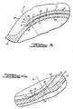
- Phantom line “D” ( Figure 4) represents the outer flank surface of orbiting wrap 24 without being relieved in accordance with the present invention.
- non-orbiting wrap 30 has a modified offset surface 60 extending approximately 8° to 9° between points "E” and “F” and a ramp surface 62 tapering at a constant rate radially outwardly approximately 20° to 21° from point "F” to a point "G", the latter representing the point where wrap 30 is back to its original profile and thickness.
- Phantom line “H” ( Figure 3) represents the outer involute flank surface of nonorbiting wrap 30 without being relieved in accordance with this invention.
- Modified surface 50 and 60 are easily formed by merely offsetting the wrap-machining cutter very slightly radially inwardly (e.g. 0.04 mm in a scroll having an orbiting wrap roughly 85 mm in overall outside diameter) to generate an offset surface parallel to the normal involute surface. Leakage is minimal because the offset is so small and because this is a relatively low pressure zone in the machine.
- orbiting wrap 24 has a portion of its radially inwardly facing flank surface adjacent its radially inner free end 42 cut away or relieved to reduce wrap thickness.
- the removed portion defines a modified surface 64 which tapers at constant rate radially outwardly from a point "J" to a point "K”.
- non-orbiting wrap 30 has a portion of its radially inwardly facing flank surface adjacent its radially inner free end 40 cut away to reduce wrap thickness, the removed portion defining a modified surface 66 which tapers at constant rate radially outwardly from a point "L” to a point "M".
- Points "J” and “L” are located at a point disposed on the wrap flank surfaces slightly radially outwardly of the point of normal separation of the wraps, preferably at the point that discharge port 32 and recess 33 are opened.
- the configuration of the discharge port 32 (and corresponding recess 33) is disclosed in detail in assignee's application entitled Scroll Machine Center Port filed of even date in the name of Gary J. Anderson, the disclosure of which is expressly incorporated herein by reference.
- Points "K” and “M” are located slightly radially inwardly of the normal separation point of wraps if they had true involute flank surfaces.
- the resulting ramps which are shown in greatly exaggerated form, smooth the transition from loading to unloading of the wrap ends. Leakage is not a problem in the ramped area because the discharge port is already opened.
Landscapes
- Engineering & Computer Science (AREA)
- Mechanical Engineering (AREA)
- General Engineering & Computer Science (AREA)
- Physics & Mathematics (AREA)
- Geometry (AREA)
- Rotary Pumps (AREA)
- Structures Of Non-Positive Displacement Pumps (AREA)
- Applications Or Details Of Rotary Compressors (AREA)
Abstract
Description
- This invention relates to scroll-type machines and more particularly to a scroll wrap configuration which reduces scroll-wrap noise and wear during operation of the machine.
- Scroll machines generally comprise mated first and second scroll members each having an end plate on which is provided an upstanding spiral wrap interleaved with the wrap on the other scroll member; the wraps engaging each other at substantially line contacts so as to define traveling pockets of varying volume as one scroll member is caused to orbit relative to the other. The machine may be a pump, compressor or expander.
- Some scroll machines have been found to have undesirable noise in operation. In trying to identify the noise it has been found that during manufacture, machining forces can cause the outer free end of one or both of the spiral wraps to be deflected slightly radially outwardly. After machining, the free end spring back to its original position thus presenting a slightly misaligned projection which can cause undesirable engagement between the respective scroll wraps during relative orbital movement. Alternatively, when scroll wraps are machined into a solid surface with no free end on the wrap, tool deflection, rather than wrap deflection, can occur which has the same end result. This engaging contact not only can result in a banging noise but can contribute to wear of the scroll assembly, and possible places additional loads on the crankshaft. Even if there is no distortion of the wrap end it is believed that this may be a relatively noisy area of the machine. Noise also can result from the sudden dynamic change in conditions at the point where the inner ends of the scroll wraps first communicate with the discharge port and/or separate from one another during operation.
- The primary object of this invention therefore resides in the provision of a scroll-type machine which overcomes the aforementioned noise and wear problems in a simple and inexpensive manner which does not result in any significant loss of efficiency.
- Other advantages and features of this invention will become apparent from the following specification taken in connection with the accompanying drawings.
-
- FIGURE 1 is a fragmentary vertical section view of the scroll assembly of a hermetic scroll-type compressor embodying the principles of the present invention;
- FIGURE 2 is a rotated section view taken generally along line 2-2 of FIGURE 1; and
- FIGURES 3 and 4 are enlarged fragmentary portions of Figure 2 showing in an exaggerated form the outer ends of the functional portions of the wraps.
- Although the principles of the present invention may be applied to many different types of scroll-type machines, the discussion herein relates to a hermetic scroll-type machine including a pair of interfitting spiral vanes of equal shape (involutes of a circle) with one being non-orbiting and the other being orbitally driven by a crankshaft, which machine has specific utility in the compression of refrigerant for air conditioning and refrigeration. A machine of the present type is disclosed in assignee's pending application, Serial No. 899,003, filed August 22, 1986 entitled Scroll-Type Machine, the disclosure of which is expressly incorporated herein by reference.
- An exemplary embodiment of a scroll compressor 10 according to the present invention comprises a
scroll assembly 12 for compressing gases, a motor (not shown), a vertically disposed crankshaft including at one end thereof a crank pin 14 for drivingly interconnecting the scroll assembly to the motor via a drive bushing 15, a compressor body 16, and a shell 18 enclosing all of the above elements. Thescroll assembly 12 includes an orbitingscroll member 20 including ascroll end plate 22 and ascroll wrap 24 of desired flank profile (e.g. an involute of a circle) upstanding therefrom, and anon-orbiting scroll member 26 including ascroll end plate 28 and ascroll wrap 30 of similar flank profile upstanding therefrom, compressor body 16 supporting orbitingend plate 22 via theusual thrust surface 31. The scroll assembly also includes acentral discharge port 32 innon-orbiting end plate 28, a similarly shaped fluid transfer recess 33 in orbitingscroll end plate 22 and a suctioninlet port area 34. - The effective ends of
wraps wrap 24 indicated at 36 and the end ofwrap 30 at 38 (this wrap is continued outwardly and circumferentially to define a suction passage but this continued portion does not act as a wrap because it never engages the orbiting wrap). The inner end ofnon-orbiting wrap 30 is indicated at 40 and the inner end of orbitingwrap 24 is indicated at 42. - In accordance with this invention it has been discovered that the benefits sought can be obtained if the outer surface of each wrap is relieved in the area thereof where it would otherwise be engaged by the outer end of the other wrap. As shown, orbiting
wrap 24 has a portion of its radially outwardly facing surface adjacent its radially outer free end 36 cut away or relieved to define a modifiedoffset surface 50 staring at point "A" at the free end of the wrap and extending approximately 180° to 190° to a point "B" (just past axis "y") and then aramp surface 52 tapering at a constant rate radially outwardly (approximately 20°) from point "B" to a point "C" whereupon the wrap surface assumes its normal involute shape. Phantom line "D" (Figure 4) represents the outer flank surface of orbitingwrap 24 without being relieved in accordance with the present invention. - Similarly,
non-orbiting wrap 30 has a modifiedoffset surface 60 extending approximately 8° to 9° between points "E" and "F" and a ramp surface 62 tapering at a constant rate radially outwardly approximately 20° to 21° from point "F" to a point "G", the latter representing the point wherewrap 30 is back to its original profile and thickness. Phantom line "H" (Figure 3) represents the outer involute flank surface ofnonorbiting wrap 30 without being relieved in accordance with this invention. - Modified
surface - It has been learned that additional benefits can be obtained by also relieving the wraps near the inner ends thereof. Thus, orbiting
wrap 24 has a portion of its radially inwardly facing flank surface adjacent its radially inner free end 42 cut away or relieved to reduce wrap thickness. The removed portion defines a modified surface 64 which tapers at constant rate radially outwardly from a point "J" to a point "K". Similarly,non-orbiting wrap 30 has a portion of its radially inwardly facing flank surface adjacent its radially innerfree end 40 cut away to reduce wrap thickness, the removed portion defining a modified surface 66 which tapers at constant rate radially outwardly from a point "L" to a point "M". Points "J" and "L" are located at a point disposed on the wrap flank surfaces slightly radially outwardly of the point of normal separation of the wraps, preferably at the point thatdischarge port 32 andrecess 33 are opened. The configuration of the discharge port 32 (and corresponding recess 33) is disclosed in detail in assignee's application entitled Scroll Machine Center Port filed of even date in the name of Gary J. Anderson, the disclosure of which is expressly incorporated herein by reference. Points "K" and "M" are located slightly radially inwardly of the normal separation point of wraps if they had true involute flank surfaces. The resulting ramps, which are shown in greatly exaggerated form, smooth the transition from loading to unloading of the wrap ends. Leakage is not a problem in the ramped area because the discharge port is already opened. - Modifying the flank surfaces in the manner described has been found to reduce noise and wear, and it is believed that it will also allow the manufacturing process to be less precise and/or faster, and thus less expensive.
Claims (16)
first and second scroll members, each of said scroll members including an end plate having an outwardly projecting spiral wrap thereon, each of said wraps having active flank surfaces and radially inner tip end portions, and outer and center ports for receiving and discharging fluid, said wraps being interleaved with each other such that said active flank surfaces of said wraps interengage each other at a plurality of spaced locations so as to define a plurality of chambers therebetween such that when one of said scroll members is caused to orbit with respect to the other said scroll member said chambers will be caused to travel between said ports, whereby fluid received in one of said chambers through one of said ports is discharged through the other of said ports, characterized in the provision of means defining a first relieved surface in the outer flank surface of one of said wraps, said relieved surface extending circumferentially inwardly along said flank surface from a point which is just circumferentially outwardly of the outer end of said flank surface on the other of said wraps which except for said relieved surface would be an active flank surface.
Applications Claiming Priority (2)
| Application Number | Priority Date | Filing Date | Title |
|---|---|---|---|
| US12386687A | 1987-11-23 | 1987-11-23 | |
| US123866 | 1987-11-23 |
Publications (3)
| Publication Number | Publication Date |
|---|---|
| EP0318189A2 true EP0318189A2 (en) | 1989-05-31 |
| EP0318189A3 EP0318189A3 (en) | 1989-12-27 |
| EP0318189B1 EP0318189B1 (en) | 1993-03-31 |
Family
ID=22411371
Family Applications (1)
| Application Number | Title | Priority Date | Filing Date |
|---|---|---|---|
| EP88310678A Expired - Lifetime EP0318189B1 (en) | 1987-11-23 | 1988-11-11 | Scroll machine |
Country Status (10)
| Country | Link |
|---|---|
| EP (1) | EP0318189B1 (en) |
| JP (1) | JPH0656081B2 (en) |
| KR (1) | KR970001456B1 (en) |
| CN (1) | CN1012200B (en) |
| AU (1) | AU611970B2 (en) |
| BR (1) | BR8806152A (en) |
| DE (1) | DE3879887T2 (en) |
| ES (1) | ES2034944T3 (en) |
| IN (1) | IN170806B (en) |
| MX (1) | MX169843B (en) |
Cited By (8)
| Publication number | Priority date | Publication date | Assignee | Title |
|---|---|---|---|---|
| GB2230053A (en) * | 1989-03-06 | 1990-10-10 | American Standard Inc | Scroll apparatus with modified scroll profile |
| DE4092107T (en) * | 1989-11-02 | 1991-10-10 | ||
| EP0601959A1 (en) * | 1992-12-07 | 1994-06-15 | Carrier Corporation | Scroll compressor |
| US5395222A (en) * | 1989-11-02 | 1995-03-07 | Matsushita Electric Industrial Co., Ltd. | Scroll compressor having recesses on the scroll wraps |
| EP0907024A1 (en) * | 1997-09-16 | 1999-04-07 | Kabushiki Kaisha Toyoda Jidoshokki Seisakusho | Scroll type compressor |
| US6257851B1 (en) | 1997-09-25 | 2001-07-10 | Scroll Technologies | Generalized minimum diameter scroll component |
| EP2466068A4 (en) * | 2009-08-12 | 2013-11-13 | Sanden Corp | Scroll fluid machine |
| EP2740938A4 (en) * | 2011-08-05 | 2015-05-06 | Mitsubishi Heavy Ind Ltd | VOLUTE ELEMENT AND FLUID MACHINE OF VOLUTE TYPE |
Families Citing this family (9)
| Publication number | Priority date | Publication date | Assignee | Title |
|---|---|---|---|---|
| JPH09100272A (en) * | 1995-08-02 | 1997-04-15 | Nippon Bayeragrochem Kk | Herbicidal thiocarbamoyltetrazolinone compound |
| JP3753886B2 (en) * | 1999-03-30 | 2006-03-08 | 三菱電機株式会社 | High precision processing equipment |
| US6592430B1 (en) | 2000-09-29 | 2003-07-15 | Mitsubishi Denki Kabushiki Kaisha | High-precision machining system |
| CN101456532B (en) * | 2005-07-04 | 2012-06-20 | 俞度立 | Micro scroll vane and method for producing micro scroll vane substrates |
| JP6267441B2 (en) * | 2013-05-28 | 2018-01-24 | 株式会社ヴァレオジャパン | Scroll compressor |
| CN104121196A (en) * | 2013-11-13 | 2014-10-29 | 柳州易舟汽车空调有限公司 | Movable disc of scroll compressor |
| CN104128645B (en) * | 2013-11-13 | 2016-11-02 | 柳州易舟汽车空调有限公司 | The processing method of orbiter |
| JP6325035B2 (en) * | 2016-08-19 | 2018-05-16 | 三菱重工サーマルシステムズ株式会社 | Scroll fluid machinery |
| CN119267221A (en) * | 2023-07-06 | 2025-01-07 | 广东美的环境科技有限公司 | Static scroll, compressor and refrigeration equipment |
Family Cites Families (9)
| Publication number | Priority date | Publication date | Assignee | Title |
|---|---|---|---|---|
| FR93048E (en) * | 1966-10-06 | 1969-01-31 | Vulliez Paul | Columetric apparatus such as a pump or the like with a circular translational cycle. |
| US3874827A (en) * | 1973-10-23 | 1975-04-01 | Niels O Young | Positive displacement scroll apparatus with axially radially compliant scroll member |
| JPS586075B2 (en) * | 1980-10-03 | 1983-02-02 | サンデン株式会社 | Scroll compressor |
| JPS57195801A (en) * | 1981-05-27 | 1982-12-01 | Sanden Corp | Fluidic device of volute type |
| JPS58172405A (en) * | 1982-04-05 | 1983-10-11 | Hitachi Ltd | Scroll fluid machine |
| US4472120A (en) * | 1982-07-15 | 1984-09-18 | Arthur D. Little, Inc. | Scroll type fluid displacement apparatus |
| JPS59142482U (en) * | 1983-03-15 | 1984-09-22 | サンデン株式会社 | Scroll type fluid device |
| JPS60252187A (en) * | 1984-05-28 | 1985-12-12 | Mitsubishi Heavy Ind Ltd | Rotary fluid machine |
| JPS61265376A (en) * | 1985-05-16 | 1986-11-25 | Mitsubishi Electric Corp | Scroll compressor |
-
1988
- 1988-11-11 DE DE8888310678T patent/DE3879887T2/en not_active Expired - Lifetime
- 1988-11-11 EP EP88310678A patent/EP0318189B1/en not_active Expired - Lifetime
- 1988-11-11 ES ES198888310678T patent/ES2034944T3/en not_active Expired - Lifetime
- 1988-11-18 IN IN959/CAL/88A patent/IN170806B/en unknown
- 1988-11-21 AU AU25743/88A patent/AU611970B2/en not_active Expired
- 1988-11-21 MX MX013878A patent/MX169843B/en unknown
- 1988-11-22 KR KR1019880015376A patent/KR970001456B1/en not_active Expired - Lifetime
- 1988-11-22 JP JP63295858A patent/JPH0656081B2/en not_active Expired - Lifetime
- 1988-11-22 CN CN88108049A patent/CN1012200B/en not_active Expired
- 1988-11-23 BR BR888806152A patent/BR8806152A/en not_active IP Right Cessation
Cited By (10)
| Publication number | Priority date | Publication date | Assignee | Title |
|---|---|---|---|---|
| GB2230053A (en) * | 1989-03-06 | 1990-10-10 | American Standard Inc | Scroll apparatus with modified scroll profile |
| GB2230053B (en) * | 1989-03-06 | 1993-05-26 | American Standard Inc | Scroll apparatus. |
| DE4092107T (en) * | 1989-11-02 | 1991-10-10 | ||
| US5395222A (en) * | 1989-11-02 | 1995-03-07 | Matsushita Electric Industrial Co., Ltd. | Scroll compressor having recesses on the scroll wraps |
| EP0601959A1 (en) * | 1992-12-07 | 1994-06-15 | Carrier Corporation | Scroll compressor |
| EP0907024A1 (en) * | 1997-09-16 | 1999-04-07 | Kabushiki Kaisha Toyoda Jidoshokki Seisakusho | Scroll type compressor |
| US6213741B1 (en) | 1997-09-16 | 2001-04-10 | Kabushiki Kaisha Toyoda Jidoshokki Seisakusho | Scroll type compressor |
| US6257851B1 (en) | 1997-09-25 | 2001-07-10 | Scroll Technologies | Generalized minimum diameter scroll component |
| EP2466068A4 (en) * | 2009-08-12 | 2013-11-13 | Sanden Corp | Scroll fluid machine |
| EP2740938A4 (en) * | 2011-08-05 | 2015-05-06 | Mitsubishi Heavy Ind Ltd | VOLUTE ELEMENT AND FLUID MACHINE OF VOLUTE TYPE |
Also Published As
| Publication number | Publication date |
|---|---|
| MX169843B (en) | 1993-07-28 |
| DE3879887T2 (en) | 1993-07-08 |
| CN1034413A (en) | 1989-08-02 |
| KR970001456B1 (en) | 1997-02-06 |
| EP0318189B1 (en) | 1993-03-31 |
| BR8806152A (en) | 1989-08-15 |
| AU611970B2 (en) | 1991-06-27 |
| ES2034944T1 (en) | 1993-04-16 |
| AU2574388A (en) | 1989-05-25 |
| CN1012200B (en) | 1991-03-27 |
| KR890008478A (en) | 1989-07-10 |
| JPH0656081B2 (en) | 1994-07-27 |
| IN170806B (en) | 1992-05-23 |
| ES2034944T3 (en) | 1993-10-01 |
| EP0318189A3 (en) | 1989-12-27 |
| JPH01163401A (en) | 1989-06-27 |
| DE3879887D1 (en) | 1993-05-06 |
Similar Documents
| Publication | Publication Date | Title |
|---|---|---|
| EP0318189B1 (en) | Scroll machine | |
| US4547137A (en) | Scroll type fluid compressor with thickened spiral elements | |
| KR100530662B1 (en) | Scroll type fluid machine | |
| US4382754A (en) | Scroll-type, positive fluid displacement apparatus with diverse clearances between scroll elements | |
| US4781549A (en) | Modified wrap scroll-type machine | |
| US4645436A (en) | Scroll type fluid displacement apparatus with improved anti-wear device | |
| US5779461A (en) | Scroll type fluid displacement apparatus having a control system of line contacts between spiral elements | |
| EP0648932B1 (en) | Scroll type compressor | |
| EP1231382B1 (en) | Scroll compressor | |
| EP0814266B1 (en) | Scroll-type fluid displacement apparatus | |
| EP0520431B1 (en) | Scroll type compressor | |
| EP1262665B1 (en) | Scroll compressor | |
| JP2804336B2 (en) | Scroll device having modified scroll shape | |
| US4927341A (en) | Scroll machine with relieved flank surface | |
| US5242283A (en) | Scroll type compressor with elongated discharge port | |
| US20010018028A1 (en) | Scroll-type fluid displacement apparatus having spiral start portion with thick base and thin tip | |
| US5807088A (en) | Scroll type compressor with chamfered scroll wall | |
| JP3601073B2 (en) | Scroll type fluid machine | |
| US4956058A (en) | Scroll type fluid displacement apparatus with surface treated spiral element | |
| US6672851B2 (en) | Scroll-type compressors | |
| US6527527B2 (en) | Scroll compressor | |
| JPH05202864A (en) | Scroll type compressor | |
| JPH11264387A (en) | Scroll fluid machine | |
| EP0838592A1 (en) | Scroll type fluid machine having an improved oldham ring | |
| JPS63173873A (en) | Scroll type fluid machine |
Legal Events
| Date | Code | Title | Description |
|---|---|---|---|
| PUAI | Public reference made under article 153(3) epc to a published international application that has entered the european phase |
Free format text: ORIGINAL CODE: 0009012 |
|
| AK | Designated contracting states |
Kind code of ref document: A2 Designated state(s): DE ES FR GB IT |
|
| PUAL | Search report despatched |
Free format text: ORIGINAL CODE: 0009013 |
|
| AK | Designated contracting states |
Kind code of ref document: A3 Designated state(s): DE ES FR GB IT |
|
| 17P | Request for examination filed |
Effective date: 19900315 |
|
| 17Q | First examination report despatched |
Effective date: 19910125 |
|
| GRAA | (expected) grant |
Free format text: ORIGINAL CODE: 0009210 |
|
| AK | Designated contracting states |
Kind code of ref document: B1 Designated state(s): DE ES FR GB IT |
|
| REF | Corresponds to: |
Ref document number: 3879887 Country of ref document: DE Date of ref document: 19930506 |
|
| ET | Fr: translation filed | ||
| ITF | It: translation for a ep patent filed | ||
| REG | Reference to a national code |
Ref country code: ES Ref legal event code: FG2A Ref document number: 2034944 Country of ref document: ES Kind code of ref document: T3 |
|
| PLBE | No opposition filed within time limit |
Free format text: ORIGINAL CODE: 0009261 |
|
| STAA | Information on the status of an ep patent application or granted ep patent |
Free format text: STATUS: NO OPPOSITION FILED WITHIN TIME LIMIT |
|
| 26N | No opposition filed | ||
| REG | Reference to a national code |
Ref country code: GB Ref legal event code: IF02 |
|
| REG | Reference to a national code |
Ref country code: GB Ref legal event code: 732E |
|
| REG | Reference to a national code |
Ref country code: FR Ref legal event code: TP |
|
| PGFP | Annual fee paid to national office [announced via postgrant information from national office to epo] |
Ref country code: ES Payment date: 20071126 Year of fee payment: 20 |
|
| PGFP | Annual fee paid to national office [announced via postgrant information from national office to epo] |
Ref country code: IT Payment date: 20071129 Year of fee payment: 20 |
|
| PGFP | Annual fee paid to national office [announced via postgrant information from national office to epo] |
Ref country code: GB Payment date: 20071128 Year of fee payment: 20 Ref country code: FR Payment date: 20071119 Year of fee payment: 20 |
|
| PGFP | Annual fee paid to national office [announced via postgrant information from national office to epo] |
Ref country code: DE Payment date: 20071221 Year of fee payment: 20 |
|
| REG | Reference to a national code |
Ref country code: GB Ref legal event code: PE20 Expiry date: 20081110 |
|
| REG | Reference to a national code |
Ref country code: ES Ref legal event code: FD2A Effective date: 20081112 |
|
| PG25 | Lapsed in a contracting state [announced via postgrant information from national office to epo] |
Ref country code: ES Free format text: LAPSE BECAUSE OF EXPIRATION OF PROTECTION Effective date: 20081112 |
|
| PG25 | Lapsed in a contracting state [announced via postgrant information from national office to epo] |
Ref country code: GB Free format text: LAPSE BECAUSE OF EXPIRATION OF PROTECTION Effective date: 20081110 |