EP0318232A1 - Insulated pipe - Google Patents
Insulated pipe Download PDFInfo
- Publication number
- EP0318232A1 EP0318232A1 EP88311013A EP88311013A EP0318232A1 EP 0318232 A1 EP0318232 A1 EP 0318232A1 EP 88311013 A EP88311013 A EP 88311013A EP 88311013 A EP88311013 A EP 88311013A EP 0318232 A1 EP0318232 A1 EP 0318232A1
- Authority
- EP
- European Patent Office
- Prior art keywords
- pipe
- secondary tube
- tube
- perforations
- insulation material
- Prior art date
- Legal status (The legal status is an assumption and is not a legal conclusion. Google has not performed a legal analysis and makes no representation as to the accuracy of the status listed.)
- Withdrawn
Links
Images

Classifications
-
- F—MECHANICAL ENGINEERING; LIGHTING; HEATING; WEAPONS; BLASTING
- F16—ENGINEERING ELEMENTS AND UNITS; GENERAL MEASURES FOR PRODUCING AND MAINTAINING EFFECTIVE FUNCTIONING OF MACHINES OR INSTALLATIONS; THERMAL INSULATION IN GENERAL
- F16L—PIPES; JOINTS OR FITTINGS FOR PIPES; SUPPORTS FOR PIPES, CABLES OR PROTECTIVE TUBING; MEANS FOR THERMAL INSULATION IN GENERAL
- F16L55/00—Devices or appurtenances for use in, or in connection with, pipes or pipe systems
- F16L55/02—Energy absorbers; Noise absorbers
- F16L55/033—Noise absorbers
- F16L55/0336—Noise absorbers by means of sound-absorbing materials
-
- F—MECHANICAL ENGINEERING; LIGHTING; HEATING; WEAPONS; BLASTING
- F01—MACHINES OR ENGINES IN GENERAL; ENGINE PLANTS IN GENERAL; STEAM ENGINES
- F01N—GAS-FLOW SILENCERS OR EXHAUST APPARATUS FOR MACHINES OR ENGINES IN GENERAL; GAS-FLOW SILENCERS OR EXHAUST APPARATUS FOR INTERNAL-COMBUSTION ENGINES
- F01N13/00—Exhaust or silencing apparatus characterised by constructional features
- F01N13/14—Exhaust or silencing apparatus characterised by constructional features having thermal insulation
-
- F—MECHANICAL ENGINEERING; LIGHTING; HEATING; WEAPONS; BLASTING
- F01—MACHINES OR ENGINES IN GENERAL; ENGINE PLANTS IN GENERAL; STEAM ENGINES
- F01N—GAS-FLOW SILENCERS OR EXHAUST APPARATUS FOR MACHINES OR ENGINES IN GENERAL; GAS-FLOW SILENCERS OR EXHAUST APPARATUS FOR INTERNAL-COMBUSTION ENGINES
- F01N13/00—Exhaust or silencing apparatus characterised by constructional features
- F01N13/14—Exhaust or silencing apparatus characterised by constructional features having thermal insulation
- F01N13/141—Double-walled exhaust pipes or housings
-
- F—MECHANICAL ENGINEERING; LIGHTING; HEATING; WEAPONS; BLASTING
- F01—MACHINES OR ENGINES IN GENERAL; ENGINE PLANTS IN GENERAL; STEAM ENGINES
- F01N—GAS-FLOW SILENCERS OR EXHAUST APPARATUS FOR MACHINES OR ENGINES IN GENERAL; GAS-FLOW SILENCERS OR EXHAUST APPARATUS FOR INTERNAL-COMBUSTION ENGINES
- F01N3/00—Exhaust or silencing apparatus having means for purifying, rendering innocuous, or otherwise treating exhaust
- F01N3/08—Exhaust or silencing apparatus having means for purifying, rendering innocuous, or otherwise treating exhaust for rendering innocuous
- F01N3/10—Exhaust or silencing apparatus having means for purifying, rendering innocuous, or otherwise treating exhaust for rendering innocuous by thermal or catalytic conversion of noxious components of exhaust
- F01N3/24—Exhaust or silencing apparatus having means for purifying, rendering innocuous, or otherwise treating exhaust for rendering innocuous by thermal or catalytic conversion of noxious components of exhaust characterised by constructional aspects of converting apparatus
- F01N3/28—Construction of catalytic reactors
- F01N3/2803—Construction of catalytic reactors characterised by structure, by material or by manufacturing of catalyst support
-
- F—MECHANICAL ENGINEERING; LIGHTING; HEATING; WEAPONS; BLASTING
- F16—ENGINEERING ELEMENTS AND UNITS; GENERAL MEASURES FOR PRODUCING AND MAINTAINING EFFECTIVE FUNCTIONING OF MACHINES OR INSTALLATIONS; THERMAL INSULATION IN GENERAL
- F16L—PIPES; JOINTS OR FITTINGS FOR PIPES; SUPPORTS FOR PIPES, CABLES OR PROTECTIVE TUBING; MEANS FOR THERMAL INSULATION IN GENERAL
- F16L59/00—Thermal insulation in general
- F16L59/14—Arrangements for the insulation of pipes or pipe systems
-
- F—MECHANICAL ENGINEERING; LIGHTING; HEATING; WEAPONS; BLASTING
- F16—ENGINEERING ELEMENTS AND UNITS; GENERAL MEASURES FOR PRODUCING AND MAINTAINING EFFECTIVE FUNCTIONING OF MACHINES OR INSTALLATIONS; THERMAL INSULATION IN GENERAL
- F16L—PIPES; JOINTS OR FITTINGS FOR PIPES; SUPPORTS FOR PIPES, CABLES OR PROTECTIVE TUBING; MEANS FOR THERMAL INSULATION IN GENERAL
- F16L59/00—Thermal insulation in general
- F16L59/14—Arrangements for the insulation of pipes or pipe systems
- F16L59/147—Arrangements for the insulation of pipes or pipe systems the insulation being located inwardly of the outer surface of the pipe
-
- F—MECHANICAL ENGINEERING; LIGHTING; HEATING; WEAPONS; BLASTING
- F16—ENGINEERING ELEMENTS AND UNITS; GENERAL MEASURES FOR PRODUCING AND MAINTAINING EFFECTIVE FUNCTIONING OF MACHINES OR INSTALLATIONS; THERMAL INSULATION IN GENERAL
- F16L—PIPES; JOINTS OR FITTINGS FOR PIPES; SUPPORTS FOR PIPES, CABLES OR PROTECTIVE TUBING; MEANS FOR THERMAL INSULATION IN GENERAL
- F16L9/00—Rigid pipes
- F16L9/21—Rigid pipes made of sound-absorbing materials or with sound-absorbing structure
-
- F—MECHANICAL ENGINEERING; LIGHTING; HEATING; WEAPONS; BLASTING
- F01—MACHINES OR ENGINES IN GENERAL; ENGINE PLANTS IN GENERAL; STEAM ENGINES
- F01N—GAS-FLOW SILENCERS OR EXHAUST APPARATUS FOR MACHINES OR ENGINES IN GENERAL; GAS-FLOW SILENCERS OR EXHAUST APPARATUS FOR INTERNAL-COMBUSTION ENGINES
- F01N13/00—Exhaust or silencing apparatus characterised by constructional features
- F01N13/08—Other arrangements or adaptations of exhaust conduits
-
- F—MECHANICAL ENGINEERING; LIGHTING; HEATING; WEAPONS; BLASTING
- F01—MACHINES OR ENGINES IN GENERAL; ENGINE PLANTS IN GENERAL; STEAM ENGINES
- F01N—GAS-FLOW SILENCERS OR EXHAUST APPARATUS FOR MACHINES OR ENGINES IN GENERAL; GAS-FLOW SILENCERS OR EXHAUST APPARATUS FOR INTERNAL-COMBUSTION ENGINES
- F01N2470/00—Structure or shape of exhaust gas passages, pipes or tubes
- F01N2470/12—Tubes being corrugated
-
- F—MECHANICAL ENGINEERING; LIGHTING; HEATING; WEAPONS; BLASTING
- F01—MACHINES OR ENGINES IN GENERAL; ENGINE PLANTS IN GENERAL; STEAM ENGINES
- F01N—GAS-FLOW SILENCERS OR EXHAUST APPARATUS FOR MACHINES OR ENGINES IN GENERAL; GAS-FLOW SILENCERS OR EXHAUST APPARATUS FOR INTERNAL-COMBUSTION ENGINES
- F01N2470/00—Structure or shape of exhaust gas passages, pipes or tubes
- F01N2470/24—Concentric tubes or tubes being concentric to housing, e.g. telescopically assembled
-
- Y—GENERAL TAGGING OF NEW TECHNOLOGICAL DEVELOPMENTS; GENERAL TAGGING OF CROSS-SECTIONAL TECHNOLOGIES SPANNING OVER SEVERAL SECTIONS OF THE IPC; TECHNICAL SUBJECTS COVERED BY FORMER USPC CROSS-REFERENCE ART COLLECTIONS [XRACs] AND DIGESTS
- Y02—TECHNOLOGIES OR APPLICATIONS FOR MITIGATION OR ADAPTATION AGAINST CLIMATE CHANGE
- Y02A—TECHNOLOGIES FOR ADAPTATION TO CLIMATE CHANGE
- Y02A50/00—TECHNOLOGIES FOR ADAPTATION TO CLIMATE CHANGE in human health protection, e.g. against extreme weather
- Y02A50/20—Air quality improvement or preservation, e.g. vehicle emission control or emission reduction by using catalytic converters
Definitions
- the present invention relates to an insulated pipe which may be used, for example, in an exhaust system such as may be used in a motor vehicle. More particularly, but not exclusively, the invention relates to an insulated pipe which can be used in addition to or to replace a conventional exhaust silencing system.
- an insulated pipe which comprises a primary pipe, a secondary tube mounted within the pipe and spaced therefrom and insulation material provided in the space between the secondary tube and the pipe, wherein the secondary tube is open at each end and extends along at least a part of the axial length of the pipe, the tube being provided with a plurality of perforations so as to permit communication between the spaces on either side of the secondary tube.
- the annular cross-sectional area of the insulation material in the axial direction of the pipe along at least a part of the length of the pipe is small relative to the cross-section area of the pipe.
- the insulation material may be a fibrous material, preferably of a type resistant to extrusion through the perforations.
- the perforations in the secondary tube are of such a number and size to reduce the thermal capacity of the secondary tube to at least about half of the thermal capacity of an equivalent unperforated tube.
- the secondary tube may be made of at least two laminations, preferably with the perforations in each of the laminations being of different sizes.
- the secondary tube may be formed with at least one bellows member.
- the or at least one bellows member may be positioned at a bend in the primary pipe.
- the primary pipe may be made of two half pressings.
- the primary pipe may be formed with at least one region of enlarged cross-sectional area.
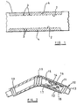
- Figure 1 shows a part of an insulated pipe for use, for example, in a vehicle exhaust system and which comprises a primary pipe 1 having a secondary tube 2 mounted within the pipe 1.
- the tube 2 is spaced from the pipe 1 except in the region of the ends of the tube 2 where the tube is supported by the pipe 1, but does not significantly inhibit the passage of exhaust gases through the pipe.
- the tube 2 is provided with a number of perforations 3 which enable the space between the tube 2 and the pipe 1 to communicate with the space within the tube 2.
- the size and number of the perforations is sufficient to reduce the thermal capacity and thermal inertia of the tube to at least about half that of an equivalent unperforated tube.
- an insulation material 4 such as a fibrous insulation material of a type resistant to extrusion through the perforations 3.
- the insulation material 4 assists in silencing the engine exhaust as well as functioning as insulation.
- the cross-sectional area of the insulation material in the axial direction of the pipe is small relative to the cross-sectional area of the pipe.
- FIG 2 shows an alternative construction of a part of an insulated pipe, for example for use in a vehicle exhaust system.
- the insulated pipe shown in Figure 2 comprises a primary pipe 10 which is constructed from two half-pressings 11,12. However, it is also possible to make the pipe 10 as a full tube and to feed the secondary tube 13 together with insulation material 14 from one end of the pipe 10.
- the primary pipe 10 is effectively the structural member of the insulated pipe and provides support for the secondary tube 13 and the insulation material 14.
- the secondary tube 13 is made from a laminate of two or more sheets depending upon the anticipated conditions of use of the insulated pipe. As shown in Figure 2, the secondary tube 13 comprises a first lamination 15 and a second lamination 16, the two laminations having perforations 17,18 respectively of different sizes. We have found that the provision of perforations 17,18 of different sizes in the laminations maximises gas flow across the secondary tube 13 while avoiding any difficulties in alignment which would arise if perforations of substantially similar sizes were to be used. To reduce thermal inertia and to provide a modicum of silencing each lamination is perforated to the maximum amount possible while retaining adequate strength.
- the bellows sections 19 are preferably positioned to coincide with the bend points of the insulated pipe. This assists in maintaining the spacing between the secondary tube 13 and the primary pipe 10. In addition to maintaining the spacing between the secondary tube 13 and the primary pipe 10 along the length of the insulated pipe, the bellows sections 19 serve to hold the insulation material 14 in place.
- the secondary tube 13 does not significantly inhibit the passage of exhaust gases through the pipe.
- FIG 3 represents a development of the embodiment shown in Figure 2.
- the insulated pipe shown in Figure 3 effectively forms the silencing system of a motor vehicle and comprises a primary pipe 20 which is made of two half pressings (not shown in detail). Although the pipe 20 is shown in one part it is possible to divide the pipe into two or more parts.
- the primary pipe 20 is shaped to take advantage of various underfloor recesses 21,22,23 of a vehicle by expanding the cross-sectional area of the pipe in these areas to allow for additional silencing, the provision of catalyst or structural strength.
- enlarged sections 24,25,26,27 are formed in the pipe 20.
- the space within the pipe is filled with insulation material as are the enlarged sections 24,25,26,27, although one or more of the enlarged sections may alternatively be filled with catalyst.
- the different sizes of the enlarged sections attenuate different frequencies of exhaust noise without significantly restricting gas flow.
- the insulated pipe according to the present invention not only provides the required insulation but also improves the silencing of the engine exhaust.
- a relatively short length of insulated pipe when combined with conventional silencing means provides additional silencing is of considerable importance particularly in so-called luxury cars where inadequate underfloor space often exists for a truly efficient and/or quiet conventional system.
- external radiated noise is much reduced when compared with conventional exhaust systems.
Landscapes
- Engineering & Computer Science (AREA)
- General Engineering & Computer Science (AREA)
- Mechanical Engineering (AREA)
- Chemical & Material Sciences (AREA)
- Combustion & Propulsion (AREA)
- Chemical Kinetics & Catalysis (AREA)
- Health & Medical Sciences (AREA)
- Toxicology (AREA)
- Exhaust Silencers (AREA)
- Exhaust Gas After Treatment (AREA)
- Pipe Accessories (AREA)
- Thermal Insulation (AREA)
Abstract
An insulated pipe which may be used, for example, in an exhaust system for a motor vehicle comprises a primary pipe (1), a secondary tube (2) mounted within the pipe and spaced therefrom and insulation material (4) provided in the space between the secondary tube and the primary pipe. The secondary tube (2) is open at each end and extends along at least a part of the axial length of the pipe, the tube being provided with a plurality of perforations (3) so as to permit communication between the spaces on either side of the secondary tube.
Description
- The present invention relates to an insulated pipe which may be used, for example, in an exhaust system such as may be used in a motor vehicle. More particularly, but not exclusively, the invention relates to an insulated pipe which can be used in addition to or to replace a conventional exhaust silencing system.
- In exhaust systems where heat is to be conserved, for example for improved catalyst light-off, or in order to protect equipment mounted close to the system, it is known to provide insulation externally of the exhaust pipe or to provide a secondary skin spaced externally or internally of the exhaust pipe. However, such exhaust systems have a significant thermal capacity and thermal inertia and do not contribute significantly to silencing of the engine exhaust.
- It is an object of the present invention to provide an insulated pipe which has a relatively low thermal capacity and thermal inertia and which in use can contribute to the silencing of the engine exhaust.
- According to the present invention there is provided an insulated pipe which comprises a primary pipe, a secondary tube mounted within the pipe and spaced therefrom and insulation material provided in the space between the secondary tube and the pipe, wherein the secondary tube is open at each end and extends along at least a part of the axial length of the pipe, the tube being provided with a plurality of perforations so as to permit communication between the spaces on either side of the secondary tube.
- Preferably the annular cross-sectional area of the insulation material in the axial direction of the pipe along at least a part of the length of the pipe is small relative to the cross-section area of the pipe.
- The insulation material may be a fibrous material, preferably of a type resistant to extrusion through the perforations.
- Preferably the perforations in the secondary tube are of such a number and size to reduce the thermal capacity of the secondary tube to at least about half of the thermal capacity of an equivalent unperforated tube.
- The secondary tube may be made of at least two laminations, preferably with the perforations in each of the laminations being of different sizes.
- The secondary tube may be formed with at least one bellows member. The or at least one bellows member may be positioned at a bend in the primary pipe.
- The primary pipe may be made of two half pressings.
- The primary pipe may be formed with at least one region of enlarged cross-sectional area.
- For a better understanding of the present invention and to show more clearly how it may be carried into effect reference will now be made, by way of example, to the accompanying drawings in which:
- Figure 1 is a diagrammatic cross-sectional view through one embodiment of an insulated pipe according to the present invention;
- Figure 2 is a cross-sectional view through a second embodiment of an insulated pipe according to the present invention; and
- Figure 3 is a view of part of an underside of a vehicle which incorporates a third embodiment of an insulated pipe according to the present invention.
- Figure 1 shows a part of an insulated pipe for use, for example, in a vehicle exhaust system and which comprises a primary pipe 1 having a
secondary tube 2 mounted within the pipe 1. Thetube 2 is spaced from the pipe 1 except in the region of the ends of thetube 2 where the tube is supported by the pipe 1, but does not significantly inhibit the passage of exhaust gases through the pipe. - The
tube 2 is provided with a number ofperforations 3 which enable the space between thetube 2 and the pipe 1 to communicate with the space within thetube 2. - The size and number of the perforations is sufficient to reduce the thermal capacity and thermal inertia of the tube to at least about half that of an equivalent unperforated tube.
- Packed into the space between the
tube 2 and the pipe 1 is aninsulation material 4 such as a fibrous insulation material of a type resistant to extrusion through theperforations 3. Theinsulation material 4 assists in silencing the engine exhaust as well as functioning as insulation. - The cross-sectional area of the insulation material in the axial direction of the pipe is small relative to the cross-sectional area of the pipe.
- Figure 2 shows an alternative construction of a part of an insulated pipe, for example for use in a vehicle exhaust system. The insulated pipe shown in Figure 2 comprises a
primary pipe 10 which is constructed from two half-pressings pipe 10 as a full tube and to feed thesecondary tube 13 together withinsulation material 14 from one end of thepipe 10. Theprimary pipe 10 is effectively the structural member of the insulated pipe and provides support for thesecondary tube 13 and theinsulation material 14. - The
secondary tube 13 is made from a laminate of two or more sheets depending upon the anticipated conditions of use of the insulated pipe. As shown in Figure 2, thesecondary tube 13 comprises afirst lamination 15 and asecond lamination 16, the twolaminations having perforations perforations secondary tube 13 while avoiding any difficulties in alignment which would arise if perforations of substantially similar sizes were to be used. To reduce thermal inertia and to provide a modicum of silencing each lamination is perforated to the maximum amount possible while retaining adequate strength. - Spaced along the length of the
secondary tube 13 and formed integrally therewith are a number ofbellows sections 19. Where there is a bend in the insulated pipe, for example as shown in Figure 2, the bellows sections are preferably positioned to coincide with the bend points of the insulated pipe. This assists in maintaining the spacing between thesecondary tube 13 and theprimary pipe 10. In addition to maintaining the spacing between thesecondary tube 13 and theprimary pipe 10 along the length of the insulated pipe, thebellows sections 19 serve to hold theinsulation material 14 in place. Thesecondary tube 13 does not significantly inhibit the passage of exhaust gases through the pipe. - Figure 3 represents a development of the embodiment shown in Figure 2. The insulated pipe shown in Figure 3 effectively forms the silencing system of a motor vehicle and comprises a
primary pipe 20 which is made of two half pressings (not shown in detail). Although thepipe 20 is shown in one part it is possible to divide the pipe into two or more parts. Theprimary pipe 20 is shaped to take advantage ofvarious underfloor recesses sections pipe 20. The space within the pipe is filled with insulation material as are the enlargedsections - Other features of the embodiment shown in Figure 3, such as the construction of
secondary tube 28 are essentially as described with reference to Figure 2. - We have found that the insulated pipe according to the present invention not only provides the required insulation but also improves the silencing of the engine exhaust.
- A relatively short length of insulated pipe when combined with conventional silencing means provides additional silencing is of considerable importance particularly in so-called luxury cars where inadequate underfloor space often exists for a truly efficient and/or quiet conventional system. However, by making substantially the entire exhaust system out of the insulated pipe we have found that external radiated noise is much reduced when compared with conventional exhaust systems.
Claims (11)
1. An insulated pipe which comprises a primary pipe (1), a secondary tube (2) mounted within the pipe and spaced therefrom and insulation material (4) provided in the space between the secondary tube and the pipe characterised in that the secondary tube (2) is open at each end and extends along at least a part of the axial length of the pipe, the tube being provided with a plurality of perforations (3) so as to permit communication between the spaces on either side of the secondary tube.
2. A pipe as claimed in claim 1, characterised in that the annular cross-sectional area of the insulation material in the axial direction of the pipe along at least a part of the length of the pipe is small relative to the cross-sectional area of the pipe.
3. A pipe as claimed in claim 1 or 2, characterised in that the insulation material is a fibrous material.
4. A pipe as claimed in claim 3, characterised in that the insulation material is of a type resistant to extrusion through the perforations.
5. A pipe as claimed in any preceding claim, characterised in that the perforations in the secondary tube are of such a number and size to reduce the thermal capacity of the secondary tube to at least about half of the thermal capacity of an equivalent unperforated tube.
6. A pipe as claimed in any preceding claim, characterised in that the secondary tube is made of at least two laminations (15,16).
7. A pipe as claimed in claim 6, characterised in that the perforations (17,18) in each of the laminations (15,16) are of different sizes.
8. A pipe as claimed in any preceding claim, characterised in that the secondary tube is formed with at least one bellows member (19).
9. A pipe as claimed in claim 8, characterised in that the or at least one bellows member is positioned at a bend in the primary pipe.
10. A pipe as claimed in any preceding claim, characterised in that the primary pipe is made of two half-pressings.
11. A pipe as claimed in any preceding claim, characterised in that the primary pipe is formed with at least one region of enlarged cross-sectional area.
Applications Claiming Priority (2)
| Application Number | Priority Date | Filing Date | Title |
|---|---|---|---|
| GB878727694A GB8727694D0 (en) | 1987-11-26 | 1987-11-26 | Insulated pipe |
| GB8727694 | 1987-11-26 |
Publications (1)
| Publication Number | Publication Date |
|---|---|
| EP0318232A1 true EP0318232A1 (en) | 1989-05-31 |
Family
ID=10627576
Family Applications (1)
| Application Number | Title | Priority Date | Filing Date |
|---|---|---|---|
| EP88311013A Withdrawn EP0318232A1 (en) | 1987-11-26 | 1988-11-22 | Insulated pipe |
Country Status (3)
| Country | Link |
|---|---|
| EP (1) | EP0318232A1 (en) |
| JP (1) | JPH01247898A (en) |
| GB (1) | GB8727694D0 (en) |
Cited By (9)
| Publication number | Priority date | Publication date | Assignee | Title |
|---|---|---|---|---|
| DE3920600A1 (en) * | 1989-06-23 | 1991-01-10 | Audi Ag | METHOD FOR PRODUCING A HOT GAS CONTAINING DOUBLE-WALLED TUBE |
| DE3926919A1 (en) * | 1989-08-16 | 1991-02-21 | Motoren Werke Mannheim Ag | Gas conveyor duct for combustion engine - has insulating lining of metal casing and connecting ceramic fibre layer, with elastic expansion pieces |
| FR2697613A1 (en) * | 1992-11-03 | 1994-05-06 | Lhotellier Montrichard Sa | Gas floe duct - made from two concentric layers of woven organic mineral material with space between filled with sound-absorbing substance |
| EP0665404A1 (en) * | 1994-01-28 | 1995-08-02 | Westaflex-Automobile S.A. | A gas transport hose |
| US6234211B1 (en) | 1997-04-30 | 2001-05-22 | Westaflex Automobile | Pipe for the ducting of gaseous fluids notably in cars |
| WO2002052184A3 (en) * | 2000-12-22 | 2002-09-06 | Mitsui Babcock Energy Ltd | Insulated compound pipe |
| EP2520844A1 (en) * | 2011-05-02 | 2012-11-07 | Tru-Flex Metal Hose, LLC | Internally insulated rigid exhaust system and method for making same |
| CN103016859A (en) * | 2012-12-06 | 2013-04-03 | 哈尔滨工程大学 | Shunting and silencing air pipe |
| CN104500869A (en) * | 2014-11-25 | 2015-04-08 | 南通四通林业机械制造安装有限公司 | Dryer air pipe with noise reduction function |
Citations (4)
| Publication number | Priority date | Publication date | Assignee | Title |
|---|---|---|---|---|
| US2089492A (en) * | 1935-07-06 | 1937-08-10 | American Radiator Co | Duct |
| FR853854A (en) * | 1938-11-18 | 1940-03-30 | Ventil Atel | Silencers for ventilation ducts and others |
| DE2341055A1 (en) * | 1972-08-15 | 1974-02-28 | Smiths Industries Ltd | PIPE |
| DE2259631A1 (en) * | 1972-12-06 | 1974-06-20 | Mobil Oil Corp | HEATING DEVICE |
-
1987
- 1987-11-26 GB GB878727694A patent/GB8727694D0/en active Pending
-
1988
- 1988-11-22 EP EP88311013A patent/EP0318232A1/en not_active Withdrawn
- 1988-11-25 JP JP63297991A patent/JPH01247898A/en active Pending
Patent Citations (4)
| Publication number | Priority date | Publication date | Assignee | Title |
|---|---|---|---|---|
| US2089492A (en) * | 1935-07-06 | 1937-08-10 | American Radiator Co | Duct |
| FR853854A (en) * | 1938-11-18 | 1940-03-30 | Ventil Atel | Silencers for ventilation ducts and others |
| DE2341055A1 (en) * | 1972-08-15 | 1974-02-28 | Smiths Industries Ltd | PIPE |
| DE2259631A1 (en) * | 1972-12-06 | 1974-06-20 | Mobil Oil Corp | HEATING DEVICE |
Cited By (11)
| Publication number | Priority date | Publication date | Assignee | Title |
|---|---|---|---|---|
| DE3920600A1 (en) * | 1989-06-23 | 1991-01-10 | Audi Ag | METHOD FOR PRODUCING A HOT GAS CONTAINING DOUBLE-WALLED TUBE |
| DE3926919A1 (en) * | 1989-08-16 | 1991-02-21 | Motoren Werke Mannheim Ag | Gas conveyor duct for combustion engine - has insulating lining of metal casing and connecting ceramic fibre layer, with elastic expansion pieces |
| DE3926919C2 (en) * | 1989-08-16 | 1998-02-05 | Motoren Werke Mannheim Ag | Exhaust duct with insulating pipe element |
| FR2697613A1 (en) * | 1992-11-03 | 1994-05-06 | Lhotellier Montrichard Sa | Gas floe duct - made from two concentric layers of woven organic mineral material with space between filled with sound-absorbing substance |
| EP0665404A1 (en) * | 1994-01-28 | 1995-08-02 | Westaflex-Automobile S.A. | A gas transport hose |
| US6234211B1 (en) | 1997-04-30 | 2001-05-22 | Westaflex Automobile | Pipe for the ducting of gaseous fluids notably in cars |
| WO2002052184A3 (en) * | 2000-12-22 | 2002-09-06 | Mitsui Babcock Energy Ltd | Insulated compound pipe |
| US7578315B2 (en) | 2000-12-22 | 2009-08-25 | Doosan Babcock Energy Limited | Compound pipe |
| EP2520844A1 (en) * | 2011-05-02 | 2012-11-07 | Tru-Flex Metal Hose, LLC | Internally insulated rigid exhaust system and method for making same |
| CN103016859A (en) * | 2012-12-06 | 2013-04-03 | 哈尔滨工程大学 | Shunting and silencing air pipe |
| CN104500869A (en) * | 2014-11-25 | 2015-04-08 | 南通四通林业机械制造安装有限公司 | Dryer air pipe with noise reduction function |
Also Published As
| Publication number | Publication date |
|---|---|
| JPH01247898A (en) | 1989-10-03 |
| GB8727694D0 (en) | 1987-12-31 |
Similar Documents
| Publication | Publication Date | Title |
|---|---|---|
| EP0117602B1 (en) | Catalytic converter substrate | |
| US4946822A (en) | Catalyst carrier body having a supporting wall and a method for producing the same | |
| CA1309356C (en) | Stamp formed muffler and catalytic converter assembly | |
| US5173577A (en) | Stamp formed muffler with low back pressure | |
| EP0217493A1 (en) | Catalytic converter substrate | |
| US5110561A (en) | Exhaust gas cleaning device | |
| EP0564692B1 (en) | Stamp formed muffler with inline expansion chamber and arcuately formed effective flow tubes | |
| US5380501A (en) | Exhaust gas cleaning device | |
| JP2694389B2 (en) | Metal honeycomb bodies, especially catalyst carrier bodies retained in inner and outer jacket tubes | |
| US3133612A (en) | Sound deadening laminated engine exhaust pipe | |
| US4993512A (en) | Exhaust duct part in particular for an internal combustion engine | |
| KR20010052134A (en) | Honeycomb arrangement with an intermediate layer containing at least one metal foil | |
| EP0687806A1 (en) | A metal carrier for a catalytic converter | |
| US4713361A (en) | Metallic catalyst body having thermal radiation protection | |
| JP2002509220A (en) | Catalytic converter for small engine silencers. | |
| KR100515216B1 (en) | Silencer casing and pertaining catalyst support with a retaining element and method for the production thereof | |
| EP0935057B1 (en) | Pipe section running along a curve | |
| US5403558A (en) | Heat and fatigue resistant metallic carrier for automobile exhaust gas-purifying catalyst | |
| JPH01247898A (en) | Insulating pipe | |
| GB2274073A (en) | Metallic honeycomb body for catalytic convertors | |
| JP2002513892A (en) | Support structure with deformation element with radial deformation limiter | |
| US8460612B2 (en) | Honeycomb body with structured sheet metal material and particle separator, catalyst carrier body and motor vehicle having the honeycomb body | |
| JP2001323814A (en) | Vehicle exhaust system double pipe | |
| EP0389645A1 (en) | Metal carrier having thermal fatigue resistance for automobile exhaust gas cleaning catalysts | |
| KR20000070873A (en) | Honeycomb body with cross-sectional area framed in the interior, particularly for small-power motors |
Legal Events
| Date | Code | Title | Description |
|---|---|---|---|
| PUAI | Public reference made under article 153(3) epc to a published international application that has entered the european phase |
Free format text: ORIGINAL CODE: 0009012 |
|
| AK | Designated contracting states |
Kind code of ref document: A1 Designated state(s): DE FR GB IT SE |
|
| 17P | Request for examination filed |
Effective date: 19890710 |
|
| STAA | Information on the status of an ep patent application or granted ep patent |
Free format text: STATUS: THE APPLICATION HAS BEEN WITHDRAWN |
|
| 18W | Application withdrawn |
Withdrawal date: 19900412 |
|
| R18W | Application withdrawn (corrected) |
Effective date: 19900412 |