EP0318284A1 - Koronaentladungsvorrichtung - Google Patents
Koronaentladungsvorrichtung Download PDFInfo
- Publication number
- EP0318284A1 EP0318284A1 EP88311125A EP88311125A EP0318284A1 EP 0318284 A1 EP0318284 A1 EP 0318284A1 EP 88311125 A EP88311125 A EP 88311125A EP 88311125 A EP88311125 A EP 88311125A EP 0318284 A1 EP0318284 A1 EP 0318284A1
- Authority
- EP
- European Patent Office
- Prior art keywords
- wall
- shield case
- guide member
- corona discharge
- discharge device
- Prior art date
- Legal status (The legal status is an assumption and is not a legal conclusion. Google has not performed a legal analysis and makes no representation as to the accuracy of the status listed.)
- Granted
Links
- 239000000463 material Substances 0.000 claims abstract description 28
- 238000004873 anchoring Methods 0.000 claims description 14
- 230000005489 elastic deformation Effects 0.000 claims description 5
- 238000000638 solvent extraction Methods 0.000 description 42
- 239000007769 metal material Substances 0.000 description 4
- 229920003023 plastic Polymers 0.000 description 4
- 239000004033 plastic Substances 0.000 description 4
- 238000004140 cleaning Methods 0.000 description 3
- 229920003002 synthetic resin Polymers 0.000 description 3
- 239000000057 synthetic resin Substances 0.000 description 3
- XAGFODPZIPBFFR-UHFFFAOYSA-N aluminium Chemical compound [Al] XAGFODPZIPBFFR-UHFFFAOYSA-N 0.000 description 2
- 229910052782 aluminium Inorganic materials 0.000 description 2
- 239000012774 insulation material Substances 0.000 description 2
- 238000000465 moulding Methods 0.000 description 2
- 238000003466 welding Methods 0.000 description 2
- BZHJMEDXRYGGRV-UHFFFAOYSA-N Vinyl chloride Chemical compound ClC=C BZHJMEDXRYGGRV-UHFFFAOYSA-N 0.000 description 1
- 239000000853 adhesive Substances 0.000 description 1
- 230000001070 adhesive effect Effects 0.000 description 1
- 239000002390 adhesive tape Substances 0.000 description 1
- 230000000994 depressogenic effect Effects 0.000 description 1
- 238000007599 discharging Methods 0.000 description 1
- 238000012986 modification Methods 0.000 description 1
- 230000004048 modification Effects 0.000 description 1
- 239000002985 plastic film Substances 0.000 description 1
- 229920006255 plastic film Polymers 0.000 description 1
- 229920000728 polyester Polymers 0.000 description 1
- 229920005989 resin Polymers 0.000 description 1
- 239000011347 resin Substances 0.000 description 1
- 230000000630 rising effect Effects 0.000 description 1
- 229920002994 synthetic fiber Polymers 0.000 description 1
Images

Classifications
-
- G—PHYSICS
- G03—PHOTOGRAPHY; CINEMATOGRAPHY; ANALOGOUS TECHNIQUES USING WAVES OTHER THAN OPTICAL WAVES; ELECTROGRAPHY; HOLOGRAPHY
- G03G—ELECTROGRAPHY; ELECTROPHOTOGRAPHY; MAGNETOGRAPHY
- G03G15/00—Apparatus for electrographic processes using a charge pattern
- G03G15/65—Apparatus which relate to the handling of copy material
- G03G15/6532—Removing a copy sheet form a xerographic drum, band or plate
- G03G15/6535—Removing a copy sheet form a xerographic drum, band or plate using electrostatic means, e.g. a separating corona
-
- H—ELECTRICITY
- H01—ELECTRIC ELEMENTS
- H01T—SPARK GAPS; OVERVOLTAGE ARRESTERS USING SPARK GAPS; SPARKING PLUGS; CORONA DEVICES; GENERATING IONS TO BE INTRODUCED INTO NON-ENCLOSED GASES
- H01T19/00—Devices providing for corona discharge
Definitions
- This invention relates to a corona discharge device which can be utilized, for example, as a peeling corona discharge device in an electrostatic copying machine.
- a peeling corona discharge device is widely utilized in an electrostatic copying machine in order to peel a sheet material such as a copying paper kept in intimate contact with a rotating drum in a transfer zone.
- the peeling corona discharge device is provided with an electrically conductive shield case and a wire stretched within the shield case, and a corona discharge generated from the wire is applied to the sheet material through an opening in the shield case.
- the corona discharge device further comprises a guide means provided at the opening of the shield case to prevent entry of the sheet material through it.
- the guide means is made of, for example, a gut, a plastic film (see, for example, Japanese Laid-Open Utility Model Publication No. 120459/1985), or a plastics member (see, for example, Japanese Laid-Open Utility Model Publication No. 181456/1984).
- the guide means When the guide means is formed of a gut, it is troublesome to set it in a stretched state. When the wire is broken, it is troublesome and time-consuming to replace the wire. Cleaning of the wire is also not easy.
- the guide means is formed of a plastics film and set between a pair of side walls, the film is likely to get out of place in the event that a relatively thick sheet material acts on it, or in the case of disposing of jamming. Cleaning of the wire is not easy, either.
- the guide means is formed of a plastics member
- deformation so-called "warping"
- warping causes part of the plastic member to rise at the time of setting it in the shield case. If this rising is large, the sheet material may collide with it, and it fails to guide the sheet.
- a corona discharge device provided with an electrically conductive shield case having a bottom wall and a pair of walls extending from both side ends of the bottom wall, a wire mounted in a stretched state within the shield case and a guide member for preventing entry of a sheet material into the shield case, wherein the guide member has a securing portion adapted to be detachably mounted on one wall of the shield case and a guide arm portion extending from the securing portion to the other wall of the shield case across an opening formed in the shield case, the guide arm portion being in press contact with the upper edge of the other wall of the shield case by elastic deformation.
- a corona discharge device provided with an electrically conductive shield case having a bottom wall and a pair of walls extending from both side of the bottom wall, a wire mounted in a stretched state within the shield case and a guide member for preventing entry of a sheet material into the shield case, wherein the guide member is formed of an elastically deformable sheet or film-like material, with one end portion being fixed to one of the walls of the shield case and the other end portion being detachably anchored selectively at said one wall and the other wall, such that when the other end portion of the guide member is anchored at the other wall, the guide member extends from the one wall to the other across an opening formed in the shield case. and when its other end portion is anchored at said one wall, the opening of the shield case is exposed.
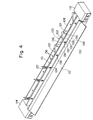
- FIGS 1 to 3 show a corona discharger to which the first embodiment of the corona discharge device of the invention is applied.
- the illustrated corona discharger is provided with an electrically conductive case 2 made of a metallic material such as aluminum.
- the case 2 has a rectangular bottom wall 4 and side walls 6 and 8 extending substantially perpendicularly from both side ends of the bottom wall 4, and an electrically conductive partitioning wall 10 formed of a metallic material is disposed between both side walls 6 and 8.
- the partitioning wall 10 is substantially L-shaped.
- Its partitioning portion 12 extends longitudinally of the case 2 in a substantially central part between the side walls 6 and 8, and its securing portion 14 is fixed to the inner surface of the right hand portion (as viewed in Figure 2) of the bottom wall 4 by welding or otherwise.
- a shield case on the right hand side of Figure 2 comprised of the side wall 6 and the partitioning wall 10 (the partitioning portion 12 and the securing portion 14) functions as a shield case of one corona discharge device.
- a shield case comprised of the side wall 8, the left hand portion of the bottom wall 4 in Figure 2, and the partitioning portion 12 of the bottom wall 10 functions as a shield case for the other corona discharge device.
- supporting members 16 (only one of which is shown in Figures 1 to 3) formed of an insulation material such as a synthetic material are mounted on both end portions of the case 2, more specifically at both its end portions between the side walls 6 and 8.
- a pair of wires 20 and 22 are stretched between these supporting members 16.
- one wire 20 extends between the side wall 6 and the partitioning portion 12 of the partitioning wall 10 longitudinally therealong, and both its end portions are fixed in place place to the right hand portions of the supporting members 16 in Figure 2.
- the other wire 22 extends between the side wall 8 and the partitioning portion 12 of the partitioning wall 10 longitudinally therealong, and both its end portions are fixed in place to the left hand portions of the supporting members 16 in Figure 2.
- Cover members 24 and 26 are attached to the opposite end portions of the case 2.
- One cover member 24 extends from the side wall 6 to the side wall 8 at the left hand end portion of the case 2 in Figures 1 and 3, and covers one supporting member 16.
- the other cover member 26 extends from the side wall 6 to the side wall 8 at the right hand end portion of the case 2 in Figures 1 and 3, and covers the other supporting member 16 (not shown).
- the corona discharger is disposed, for example, in a transfer zone opposite to a rotating drum (not shown) of an electrostatic copying machine. Accordingly, as can be easily seen, one corona discharging device comprising the shield case composed of the side wall 6 and the partitioning wall 10 and one wire 20 functions as a transfer corona discharge device for transferring a toner image formed on the surface of a photosensitive material on the rotating drum to a sheet material such as copying paper, and applies a corona discharge from the wire 20 to the back surface of the sheet material through an upper surface opening defined between the side wall 6 and the partitioning portion 12 of the partitioning wall 10.
- the other corona discharge device comprising the shield case composed of the side wall 8, the left hand part of the bottom wall 4 in Figure 2, and the partitioning portion 12 of the partitioning wall 10 and the other wire 22 functions as a peeling corona discharge device for peeling the sheet material in intimate contact with the surface of the photosensitive material on the rotating drum, and applies a corona discharge from the wire 22 to the back surface of the sheet material kept in intimate contact with the rotating drum through an upper surface opening defined between the side wall 8 and the partitioning portion 12 of the partitioning wall 10.
- the corona discharger is provided with a guide member 28 disposed in relation to the corona discharge device on the left hand side of Figure 2 (i.e., the one which functions as a peeling corona discharge device).
- the illustrated guide member 28 has a securing portion 30 and a plurality of (6 in the illustrated embodiment) guide arm portions 32 extending from the securing portion 30.
- the securing portion 30 and the guide arm portions 32 are molded from a synthetic resin as a one-piece unit.
- the securing portion 30 has an outside wall portion 34 and an inner wall portion 36 extending longitudinally in spaced-apart relationship, and a securing depression 38 is defined between the outer wall portion 34 and the inside wall portion 36 (see Figure 2).
- a plurality of (3 in the illustrated embodiment) rectangular openings 40 are formed in the outside wall portion 34 longitudinally thereof in spaced-apart relationship.
- a plurality of (2 in the illustrated embodiment) nearly hemispherical protrusions 42 are provided integrally in spaced-apart relationship in the longitudinal direction.
- the guide arm portions 32 extend from the securing portion 30 to which they are connected to the right in Figure 2, and to the right top in Figure 3.
- the guide arm portions 32 are preferably constructed as shown in Figures 1 and 3. Specifically, it is preferred that with the longitudinally central part of the guide member 28 as a standard, the guide arm 32 positioned on one side thereof (the left hand portion in Figures 1 and 3) be inclined in a straight line inwardly (to the right in Figures 1 and 3) toward the free end portion, and the guide arm portion 32 positioned on the other side of the standard (the right hand portion in Figures 1 and 3) be inclined in a straight line inwardly (to the left in Figures 1 and 3) toward the free end portion.
- the free end portion of each guide arm portion 32 is nearly spherical as shown.
- anchoring protrusions 44 are provided on the outside surface of the side wall 8 of the case 2.
- the anchoring protrusions 44 can be formed in the side wall 8 by, for example, press working.
- the guide member 28 is detachably mounted as shown in Figures 1 and 2. Specifically, the securing depression 38 defined in the securing portion 30 of the guide member 28 is brought into alignment with the side wall 8 of the case 2, and then the securing portion 30 is depressed downwardly. As a result, the upper end portion of the side wall 8 is inserted between the outside wall portion 34 positioned outwardly and the inside wall portions 36 positioned inwardly, and the guide member 28 is detachably loaded into the case 2.
- each of the guide arm portions 32 extends across the upper surface opening from one side wall of the shield case in the corona discharge device functioning as the peeling corona discharge device (i.e., the side wall 8 of the case 2) to the other side wall (i.e., the partitioning portion 12 of the partitioning wall 10), and its free end portion slightly projects toward the side wall 6 beyond the partitioning portion 12.
- the sheet material peeled from the rotating drum (not shown) is conveyed downstream while being guided by the guide arm portions 32 and its entry into the peeling corona discharge device is accurately hampered, as shown in Figures 1 and 2.
- the protrusions 42 provided in the outside wall portion 34 of the securing portion 30 act on the side wall 8 of the case 2, as shown in Figure 2.
- the inside portion 36 of the securing portion 30 is kept in press contact with the inside surface of the side wall 8 and the outside wall portion 34 is elastically deformed slightly to the left in Figure 2.
- the elastic deformation of the securing portion 30 biases the guide arm portions 32 clockwise in Figure 2 with the base portion as a fulcrum.
- the free end portions of the guide arm portions 32 are kept in press contact with the upper edge of the partitioning portion 12 by their own elastic deformation, and substantially no space is formed between the lower edges of the guide arm portions 32 and the upper edge of the partitioning portion. Consequently, entry of the sheet material between the partitioning portion 12 of the partitioning wall 10 and the guide member 28 can be accurately prevented. Furthermore, the elastic deformation of the guide member 28 can effectively compensate for any "warping" of the guide member which occurred during molding, and the guide arm portions 32 are not partly raised.
- the guide member 28 is relatively strongly pushed up in Figure 2 with respect to the case 2. This causes disengagement between the openings 40 formed in the securing portion 30 and the anchoring protrusions 44 formed in the side wall 8, and the guide member 28 is detached from the side wall 8 as is required.
- the guide member 28 can be easily loaded into, and detached, from the side wall 8.
- the wire 22 can be cleaned and replaced easily.
- the protrusions 42 for elastically deforming the guide member 28 are provided on the securing portion 30 of the guide member 28 (more specifically, in the inside surface of the outside wall portion 34). If desired, protrusions for elastically deforming the guide member 28 may be provided on the outside surface of the side wall 8.
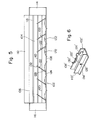
- FIGS 4 and 5 show a corona discharger to which a second embodiment of the corona discharge device in accordance with this invention is applied.
- the illustrated corona discharger is provided with an electrically conductive case 102 formed of a metallic material such as aluminum.
- the case 102 has a bottom wall 104 and side walls 106 and 108 projecting upwardly substantially vertically from both side ends of the bottom wall 104.
- an electrically conductive partitioning wall 110 formed of a metallic material and the lower end of the partitioning wall 110 is fixed to the bottom wall 104 by such means as welding.
- a shield case comprised of the bottom wall 104 (the lower portion in Figure 5), the side wall 108 and the partitioning wall 110 functions as a shield case for one corona discharge device
- a shield case comprised of the bottom wall 104 (the upper portion in Figure 5)
- the side wall 106 and the partitioning wall 110 functions as a shield case for the other corona discharge device.
- the upper portion of one side wall 106 is slightly inwardly bent toward the partitioning wall 110, and a guide member 112 is fixed to the outside surface of the side wall 106 and its one side portion projects outwardly, as shown in Figure 4.
- Supporting members 114 and 116 formed of an insulation material such as a synthetic resin material are attached to both end portions of the case 102, and wires 118 and 120 are stretched between the supporting members 114 and 116 (see Figure 5).
- One wire 118 extends along and between the side walls 106 and the partitioning wall 110, and the other wire 120 extends along and between the side wall 108 and the partitioning wall 110.
- the corona discharger as in the first embodiment, is disposed in a transfer zone opposite to the rotating drum (not shown) of an electrostatic copying machine.
- One corona discharge device including a shield case composed of the bottom wall 104, the side wall 106 and the partitioning wall 110 and one wire 118 functions as a transfer corona discharge device
- the other corona discharge device including a shield case composed of the bottom wall 104, the side wall 108 and the partitioning wall 110 and the wire 120 functions as a peeling corona discharge device.
- a guide member 122 is further disposed in regard to the other corona discharge device in the corona discharger described.
- the guide member 122 is formed of a film or sheet-like material which can be formed of a synthetic resin material such as a polyester or a vinyl chloride resin, and can be elastically deformed from a position shown in Figure 4 and by a solid line in Figure 5 to a position shown by a two-dot chain line in Figure 5.
- six guide members 122 in total are disposed in spaced-apart relationship longitudinally of the side wall 108 and the partitioning wall 110. With the longitudinally central part of the side wall 108 as a standard, three guide members 122 are provided on one side thereof (the left side in Figure 5), and three guide members 122 are provided on the other side (the right side in Figure 5).
- the guide members 122 are of substantially the same structure.
- Each of the guide members 122 has a fixed portion 124 provided at one end portion, a projecting portion 126 extending upwardly from the fixed portion 124, a guide portion 128 extending substantially horizontally from the upper end of the projecting portion 126, a suspending portion 130 extending downwardly from the end of the guide portion 128, and an anchoring projection 132 projecting nearly horizontally from the lower end of the suspending portion 130.
- the fixed portion 124 is fixed to the inside surface of the side wall 108 by an adhesive or a both-surface adhesive tape.
- a rectangular first hole 134 is formed in the partitioning wall 110 corresponding to each guide member 122.
- first holes 134 provided correspondingly to the guide members 122 disposed on one side of the longitudinally central part of the side wall 108 are positioned inwardly of the fixed portions 124 of the guide members 122, namely to the right in Figure 5.
- the first holes 134 provided correspondingly to the guide members 122 disposed on the other side of the aforesaid standard are positioned inwardly of the fixed portions 124 of the guide members 122, namely to the left in Figure 5.
- second holes 136 are formed in the side wall 108 correspondingly to the guide members 122.
- the second holes 136 are positioned further inwardly of the first holes 134.
- each guide member 122 is adapted to be selectively anchored at the partitioning wall 110 and the side wall 108.
- the anchoring projections 132 of the guide members 122 are anchored at the corresponding first holes 134, and in the anchored state, the forward ends of the anchoring projections 132 project slightly toward the side wall 106 through the partitioning wall 110.
- the guide portions 128 of the guide members 122 positioned on one side (the left hand side in Figure 5) of the side wall 108 extend inclinedly from one end toward the other inwardly to the right in Figure 5.
- the guide portions 128 of the guide members 122 positioned on the other side (on the right hand side in Figure 5) of the side wall 108 extend inclinedly from one end toward the other inwardly to the left in Figure 5.
- the guide portions 128 of the guide members 122 cross the side walls 108 and 110 while slightly projecting beyond the upper ends of the partitioning wall 110 and the side wall 108. Accordingly, the guide members 122 guide the sheet member properly and accurately prevent entry of the sheet material into the shield case of the corona discharge device functioning as a peeling corona discharge device, i.e. into the space between the partitioning wall 110 and the side wall 108.
- the action of the sheet material, etc. on the guide members 122 does not result in detachment of the guide members 122 from the case 102.
- the anchoring projections 132 of the guide members 122 are anchored at the corresponding second hole 136.
- this anchoring can be achieved by detaching the anchoring projections 132 of the guide members 122 from the first holes 134, and then elastically deforming them inwardly (clockwise in Figure 5 for the guide members 122 positioned on one side of the side wall 108, and counterclockwise in Figure 5 for the guide members 122 positioned on the other side of the side wall 108) and anchoring them in the second holes 136. Consequently, the end portions of the anchoring projections 132 project slightly outwardly through the side wall 108.
- the guide portions 128 of the guide members 122 extend nearly in the left-right direction in Figure 5 inwardly of the side wall 108 along its inside surface to expose the overhead space of the wire 120.
- the wire can be cleaned and replaced easily.
- Figure 6 shows a modified example of the corona discharger shown in Figures 4 and 5.
- the height of the side wall 108′ of the case 102′ is slightly lower than that of the partitioning wall 110′, and the guide portion 128′ as a whole of the guide member 122′ projects upwardly beyond the upper edge of the side wall 108′.
- the anchoring projection provided at the lower end of the suspending portion 130′ of the guide member 122′ is anchored at the hole 134′ formed in the partitioning wall 110′.
- the guide member 122′ When the space between the partitioning wall 110′ and the side wall 108′ is to be opened, the guide member 122′ is elastically deformed and its suspending portion 130′ is detachably anchored at the upper edge of the side wall 108′, as shown in Figure 6. Accordingly, the second holes can be omitted.
- the fixing portion 124 of the guide member 122′ is fixed to the inside surface of the side wall 108′, and the same result as in the second embodiment can be achieved.
Landscapes
- Physics & Mathematics (AREA)
- Engineering & Computer Science (AREA)
- Plasma & Fusion (AREA)
- General Physics & Mathematics (AREA)
- Electrostatic Charge, Transfer And Separation In Electrography (AREA)
Priority Applications (1)
| Application Number | Priority Date | Filing Date | Title |
|---|---|---|---|
| EP91202800A EP0469691B1 (de) | 1987-11-25 | 1988-11-24 | Glimmentladungsvorrichtung |
Applications Claiming Priority (2)
| Application Number | Priority Date | Filing Date | Title |
|---|---|---|---|
| JP1987178360U JPH0617127Y2 (ja) | 1987-11-25 | 1987-11-25 | コロナ放電器 |
| JP178360/87 | 1987-11-25 |
Related Child Applications (1)
| Application Number | Title | Priority Date | Filing Date |
|---|---|---|---|
| EP91202800.8 Division-Into | 1991-10-29 |
Publications (2)
| Publication Number | Publication Date |
|---|---|
| EP0318284A1 true EP0318284A1 (de) | 1989-05-31 |
| EP0318284B1 EP0318284B1 (de) | 1993-03-10 |
Family
ID=16047128
Family Applications (2)
| Application Number | Title | Priority Date | Filing Date |
|---|---|---|---|
| EP91202800A Expired - Lifetime EP0469691B1 (de) | 1987-11-25 | 1988-11-24 | Glimmentladungsvorrichtung |
| EP88311125A Expired - Lifetime EP0318284B1 (de) | 1987-11-25 | 1988-11-24 | Koronaentladungsvorrichtung |
Family Applications Before (1)
| Application Number | Title | Priority Date | Filing Date |
|---|---|---|---|
| EP91202800A Expired - Lifetime EP0469691B1 (de) | 1987-11-25 | 1988-11-24 | Glimmentladungsvorrichtung |
Country Status (4)
| Country | Link |
|---|---|
| US (1) | US4906841A (de) |
| EP (2) | EP0469691B1 (de) |
| JP (1) | JPH0617127Y2 (de) |
| DE (2) | DE3879116T2 (de) |
Cited By (1)
| Publication number | Priority date | Publication date | Assignee | Title |
|---|---|---|---|---|
| WO2013104753A3 (en) * | 2012-01-13 | 2013-11-21 | Oce-Technologies B.V. | Corona treatment device |
Families Citing this family (3)
| Publication number | Priority date | Publication date | Assignee | Title |
|---|---|---|---|---|
| US5229819A (en) * | 1991-09-05 | 1993-07-20 | Xerox Corporation | Protective assembly for charging apparatus |
| JP3187677B2 (ja) * | 1995-03-03 | 2001-07-11 | 京セラミタ株式会社 | 画像形成装置の転写分離部構造 |
| DE10121289A1 (de) * | 2001-05-02 | 2002-11-07 | Nexpress Solutions Llc | Vorrichtung zum Führen von Druckträgern durch eine Entladevorrichtung |
Family Cites Families (5)
| Publication number | Priority date | Publication date | Assignee | Title |
|---|---|---|---|---|
| US3778622A (en) * | 1970-09-30 | 1973-12-11 | Iwatsu Electric Co Ltd | Charging apparatus for electro-photographic copying machines |
| DE2849233C2 (de) * | 1978-11-13 | 1982-12-09 | Olympia Werke Ag, 2940 Wilhelmshaven | Elektrofotografisches Kopiergerät mit einer Übertragungseinrichtung zur Übertragung eines Tonerbildes auf ein Bildempfangsmaterial |
| JPS58138951U (ja) * | 1982-03-12 | 1983-09-19 | 株式会社リコー | 帯電装置 |
| JPH0636112B2 (ja) * | 1984-10-30 | 1994-05-11 | 株式会社東芝 | 画像形成装置 |
| US4725732A (en) * | 1986-07-02 | 1988-02-16 | Xerox Corporation | Pin corotron and scorotron assembly |
-
1987
- 1987-11-25 JP JP1987178360U patent/JPH0617127Y2/ja not_active Expired - Lifetime
-
1988
- 1988-11-22 US US07/274,965 patent/US4906841A/en not_active Expired - Lifetime
- 1988-11-24 EP EP91202800A patent/EP0469691B1/de not_active Expired - Lifetime
- 1988-11-24 DE DE8888311125T patent/DE3879116T2/de not_active Expired - Fee Related
- 1988-11-24 DE DE3853368T patent/DE3853368T2/de not_active Expired - Fee Related
- 1988-11-24 EP EP88311125A patent/EP0318284B1/de not_active Expired - Lifetime
Non-Patent Citations (2)
| Title |
|---|
| PATENT ABSTRACTS OF JAPAN, Vol. 8, No. 92 (P-271)[1529], 27th April 1984; & JP-A-59 007 969 (MATSUSHITA DENKI SANGYO K.K.) 17-01-1984 * |
| PATENT ABSTRACTS OF JAPAN, Vol. 8, No. 92 (P-271)[1529], 27th April 1984; & JP-A-59 007 971 (MATSUSHITA DENKI SANGYO K.K.) 17-01-1984 * |
Cited By (1)
| Publication number | Priority date | Publication date | Assignee | Title |
|---|---|---|---|---|
| WO2013104753A3 (en) * | 2012-01-13 | 2013-11-21 | Oce-Technologies B.V. | Corona treatment device |
Also Published As
| Publication number | Publication date |
|---|---|
| JPH0617127Y2 (ja) | 1994-05-02 |
| EP0469691B1 (de) | 1995-03-15 |
| DE3853368T2 (de) | 1995-07-27 |
| EP0469691A3 (en) | 1993-04-21 |
| US4906841A (en) | 1990-03-06 |
| EP0318284B1 (de) | 1993-03-10 |
| EP0469691A2 (de) | 1992-02-05 |
| JPH0185754U (de) | 1989-06-07 |
| DE3879116T2 (de) | 1993-09-09 |
| DE3853368D1 (de) | 1995-04-20 |
| DE3879116D1 (de) | 1993-04-15 |
Similar Documents
| Publication | Publication Date | Title |
|---|---|---|
| US12298706B2 (en) | Image forming apparatus with detectable cartridge | |
| EP0703511A2 (de) | Bilderzeugungsgerät ausgerüsted mit Reinigungsvorrichtung | |
| EP0318284A1 (de) | Koronaentladungsvorrichtung | |
| KR930002247B1 (ko) | 화상 형성장치 | |
| EP0454163A2 (de) | Tonerbehälter und Arbeitseinheit mit einem solchen Behälter | |
| JPH02163761A (ja) | プロセスカートリッジ | |
| EP0285249B1 (de) | Vorrichtung zum Entwickeln eines latenten elektrostatischen Bildes und Tonerpatrone für solche Vorrichtung | |
| US6249660B1 (en) | Imaging cartridge for use in an image forming apparatus including detachable electrode member | |
| EP0448022B1 (de) | Bilderzeugungsgerät | |
| US5842104A (en) | Image-forming device and a process unit therefor having a guide plate with multiple openings | |
| JPS63187272A (ja) | 現像器のトナ−補給装置 | |
| KR0184943B1 (ko) | 전자사진장치 | |
| US5235390A (en) | Developing device with toner cartridge cover shaped to prevent leakage | |
| JP2706437B2 (ja) | 記録装置 | |
| JP2006251754A (ja) | 装置操作方法解説シート・画像形成装置 | |
| JPH0244305Y2 (de) | ||
| KR930005738Y1 (ko) | 복사기의 카트리지 장착장치 | |
| JPS63236052A (ja) | 記録装置 | |
| US4575219A (en) | Dry process developing apparatus having detachable screening member for developing unit | |
| JPH04366980A (ja) | 画像形成装置 | |
| JPH08241024A (ja) | 画像形成装置 | |
| JP2025097349A (ja) | 画像形成装置 | |
| CA2036828C (en) | Developing device | |
| JPS5930915Y2 (ja) | 電子複写機の帯電装置 | |
| JP2706436B2 (ja) | 記録装置 |
Legal Events
| Date | Code | Title | Description |
|---|---|---|---|
| PUAI | Public reference made under article 153(3) epc to a published international application that has entered the european phase |
Free format text: ORIGINAL CODE: 0009012 |
|
| AK | Designated contracting states |
Kind code of ref document: A1 Designated state(s): DE FR GB NL |
|
| 17P | Request for examination filed |
Effective date: 19890731 |
|
| 17Q | First examination report despatched |
Effective date: 19910625 |
|
| GRAA | (expected) grant |
Free format text: ORIGINAL CODE: 0009210 |
|
| AK | Designated contracting states |
Kind code of ref document: B1 Designated state(s): DE FR GB NL |
|
| XX | Miscellaneous (additional remarks) |
Free format text: TEILANMELDUNG 91202800.8 EINGEREICHT AM 24/11/88. |
|
| REF | Corresponds to: |
Ref document number: 3879116 Country of ref document: DE Date of ref document: 19930415 |
|
| ET | Fr: translation filed | ||
| PLBE | No opposition filed within time limit |
Free format text: ORIGINAL CODE: 0009261 |
|
| STAA | Information on the status of an ep patent application or granted ep patent |
Free format text: STATUS: NO OPPOSITION FILED WITHIN TIME LIMIT |
|
| 26N | No opposition filed | ||
| PGFP | Annual fee paid to national office [announced via postgrant information from national office to epo] |
Ref country code: FR Payment date: 19951109 Year of fee payment: 8 |
|
| PGFP | Annual fee paid to national office [announced via postgrant information from national office to epo] |
Ref country code: GB Payment date: 19951115 Year of fee payment: 8 |
|
| PGFP | Annual fee paid to national office [announced via postgrant information from national office to epo] |
Ref country code: DE Payment date: 19951128 Year of fee payment: 8 |
|
| PGFP | Annual fee paid to national office [announced via postgrant information from national office to epo] |
Ref country code: NL Payment date: 19951129 Year of fee payment: 8 |
|
| PG25 | Lapsed in a contracting state [announced via postgrant information from national office to epo] |
Ref country code: GB Effective date: 19961124 |
|
| PG25 | Lapsed in a contracting state [announced via postgrant information from national office to epo] |
Ref country code: NL Effective date: 19970601 |
|
| GBPC | Gb: european patent ceased through non-payment of renewal fee |
Effective date: 19961124 |
|
| PG25 | Lapsed in a contracting state [announced via postgrant information from national office to epo] |
Ref country code: FR Effective date: 19970731 |
|
| NLV4 | Nl: lapsed or anulled due to non-payment of the annual fee |
Effective date: 19970601 |
|
| PG25 | Lapsed in a contracting state [announced via postgrant information from national office to epo] |
Ref country code: DE Effective date: 19970801 |
|
| REG | Reference to a national code |
Ref country code: FR Ref legal event code: ST |