EP0318307A2 - Armature winding machine with quick-change tooling - Google Patents
Armature winding machine with quick-change tooling Download PDFInfo
- Publication number
- EP0318307A2 EP0318307A2 EP88311173A EP88311173A EP0318307A2 EP 0318307 A2 EP0318307 A2 EP 0318307A2 EP 88311173 A EP88311173 A EP 88311173A EP 88311173 A EP88311173 A EP 88311173A EP 0318307 A2 EP0318307 A2 EP 0318307A2
- Authority
- EP
- European Patent Office
- Prior art keywords
- assembly
- armature
- outer shield
- shield
- collet
- Prior art date
- Legal status (The legal status is an assumption and is not a legal conclusion. Google has not performed a legal analysis and makes no representation as to the accuracy of the status listed.)
- Granted
Links
- 238000004804 winding Methods 0.000 title claims abstract description 40
- 230000000712 assembly Effects 0.000 claims abstract description 11
- 238000000429 assembly Methods 0.000 claims abstract description 11
- 241001155433 Centrarchus macropterus Species 0.000 claims description 10
- 238000000034 method Methods 0.000 abstract description 3
- 230000008878 coupling Effects 0.000 description 4
- 238000010168 coupling process Methods 0.000 description 4
- 238000005859 coupling reaction Methods 0.000 description 4
- 230000008859 change Effects 0.000 description 3
- 238000010276 construction Methods 0.000 description 1
- 230000000694 effects Effects 0.000 description 1
- WABPQHHGFIMREM-UHFFFAOYSA-N lead(0) Chemical compound [Pb] WABPQHHGFIMREM-UHFFFAOYSA-N 0.000 description 1
- 230000007246 mechanism Effects 0.000 description 1
Images

Classifications
-
- H—ELECTRICITY
- H02—GENERATION; CONVERSION OR DISTRIBUTION OF ELECTRIC POWER
- H02K—DYNAMO-ELECTRIC MACHINES
- H02K15/00—Processes or apparatus specially adapted for manufacturing, assembling, maintaining or repairing of dynamo-electric machines
- H02K15/08—Forming windings by laying conductors into or around core parts
- H02K15/09—Forming windings by laying conductors into or around core parts by laying conductors into slotted rotors
Definitions
- This invention relates to an armature winding machine with quick-change tooling, especially armature-specific tooling for flier-type winding machines.
- the tooling of this invention is intended primarily for use with double flier winding machines that are most generally used for winding armatures and are typically called “armature winders” but may also be used to wind other cores having radially outwardly opening slots, such as rotating cores carrying field coils.
- the invention is not so limited and may be used with single or triple flier machines and other types of winding equipment utilizing one or more winding forms.
- Typical flier-type armature winding machines used for high-speed production are essentially "dedicated” in the sense that each machine is tooled to wind but a single configuration of armature, or at best a very limited number of armatures.
- the machine tooling parts must normally be carefully machined to be armature-specific, i.e. dedicated to be used with a single armature of a given configuration, or no more than a very limited number of different configurations.
- An object of this invention is to provide a flier-type armature winding machine that may be easily and quickly changed over from being tooled to wind armatures having one set of parameters to an armature having a different set of parameters. More particularly, this invention is directed to an improved armature rotator with an armature-gripping collet assembly and to an improved commutator shield tooling assembly wherein the armature-specific parts therof may be quickly and easily removed and then quickly and easily replaced by other armature-specific parts by a person having little experience in tooling set-up techniques. This enables the machine manufacturer to produce replacement sets of armature-specific tooling parts so that a single armature winding machine may be used to produce armatures having various different configurations with minimal changeover time.
- both the inner shield assembly and the outer shield assembly include quick release means by which the armature-specific tooling parts may be quickly removed and replaced by other armature-specific tooling.
- the armature rotator assembly has a modular collet assembly which may be removed simply by manually removing a pair of connectors and replaced by another modular collet assembly. An entire tooling changeover can thus be effected by one relatively unskilled in tooling set-up techniques in a few minutes without the use of any special tools.
- this invention is shown in connection with the winding of an armature, generally designated 10, including an armature core 12 having radially inwardly directed coil-receiving slots 14 mounted on an armature shaft 16.
- a commutator 18 having plural tangs is mounted upon the same shaft 16.
- Armature 10 is merely one example of many armatures that may be wound by a flier-type winder.
- machine 20 includes an armature rotator assembly, generally designated 22, with which are associated commutator shield mechanisms comprising an inner shield assembly, generally designated 24, and an outer shield assembly, generally designated 26.
- the purpose of the armature rotator assembly 22 is to position the armature 10 as required to effect the winding of coils thereon and the connection of coil leads to the commutator 18, and the armature rotator assembly 24 has a collet 28 (FIG.
- the armature winding machine 20 further includes left and right side flier spindles 30 and 32, respectively, through which wires, designated W1 and W2, respectively, extend from suitable sources (not shown) of wire under tension.
- the wires W1 and W2 exit from flier assemblies 34 and 36, respectively, to the armature 10.
- a pair of pivotal wire clamp assemblies 38 clamp the free ends of the wires at the end of the winding of one armature until after the commencement of the winding of the next armature.
- the flier spindles 30 and 32 are rotatably driven in mutually opposite directions by a suitable motor assembly and control circuitry therefor during time the wires W1 and W2 are drawn through the flier spindles 30 and 32 and wound into the core slots 14.
- the wires are guided into the core slots 14 by left and right side form assemblies 40 and 42.
- This invention could be practiced with armature winding machines having any of various types of winding forms. However, this invention is preferably used with other armature-specific tooling devices which can be rapidly changed to accommodate different winding armatures. Winding form assemblies that may be quickly changed are disclosed in U.S. Patent Application Serial No. 125288 titled WINDING FORM ASSEMBLY, filed in the United States Patent and Trademark office on 25th November 1987.
- the armature rotator assembly 22 comprises a stepping motor 50, which through gears 52, drives a rotator spindle 54 that is hollow to receive a collet release rod 56.
- the rotator spindle 54 and the collet release rod 56 are appropriately mounted for rotation within front and rear frame plates 58 and 60, respectively, of a rotator support frame, generally designated 62, including a frame base plate 64, and a frame top plate 66.
- the rotator spindle 54 has a reduced diameter front portion 68 extending through the inner race 70 of a bearing 72 in the front frame plate 58.
- the collet release rod 56 forms part of a readily removable, modular collet assembly, generally designated 80, which also comprises the aforementioned split collet 28.
- Split collet 28 includes an armature shaft-gripping, elongated, tubular body portion 82 and an enlarged head 84 having a front collet cam surface 86 and a rear collet cam surface 88.
- the modular collet assembly 80 further comprises a tubular collet retainer 90 having, at its front end, an inwardly directed flange 92 against which the front collet cam surface 86 bears.
- a tubular collet actuator 94 Coaxially received within the retainer 90 is a tubular collet actuator 94 having a front surface 96 that bears against the rear collet cam surface 88.
- the rearward end of the collet actuator 94 is closed by a rear wall 98 having a threaded bore to which the threaded forward end portion, designated 98, of the collet release rod 56 is threadedly connected.
- Collet retainer 90 has an enlarged diameter rearward end portion 102 having, intermediate its ends, an internally threaded bore portion 104 to which a collet retainer end cap 106 is threadedly connected. End cap 106 has a central bore 108 through which the collet release rod extends.
- the actuator rear end wall 98 and the retainer end cap 106 define a chamber 110 within the enlarged diameter rear portion 102 of the retainer in which are located plural spring or Belleville washers 112.
- the collet assembly 80 comprises a unitary subassembly that may be replaced by other collet assemblies for use with armatures having different shaft, commutator, or core configurations.
- the collet assembly 80 is assembled with the other parts of the armature rotator 22 by simple, manually releasable means so that a relatievly unskilled person may assemble and disassemble the collet assembly 80 on the machine 20 in minimal time.
- the collet assembly 80 may be connected to the rotator spindle 54 by first inserting the release rod 56 into the rotator spindle 54 from its front end 68 and extending it through the extreme rearward end of the rotator spindle 54 as shown in FIG. 5. When fully assembled, as shown in FIG.
- the rearwardmost end of the enlarged rear end portion 102 of the collet retainer 90 is slipped over the forwardmost end of the reduced diameter forward portion 68 of the rotator spindle 54 extreme forward end of the rotator spindle 68.
- the rearwardmost end of the release rod 56 extends rearwardly through a collet release drive plug 114 mounted in a bearing 116 in a plug housing 118 supported on the rear frame plate 60.
- connection between the collet assembly 80 and the remainder of the rotator assembly 22 comprises a pair of disc-like, C-shaped connectors, namely a forward connector 120 and a rearward connector 122 shown in FIGS. 2, 4, 5, 6 and 7.
- a forward connector 120 shown assembled in FIGS. 4 and 7, it interconnects the forwardmost end of the rotator spindle 54 and the rearwardmost end of the collet retainer 90.
- the forwardmost end of the rotator spindle 54 has a pair of transversely extending, flats or grooves 124 and 126 along its upper and lower margins and the rearwardmost end of the collet retainer 90 has a pair of transversely extending slots 128 and 130 aligned with the grooves 124 and 126, respectively.
- the forward connector 120 may be assembled in the grooves 124 and 126 and the slots 128 and 130 to retain the collet retainer 90 releasably fixed, both rotationally and axially, relative to the rotator spindle 54.
- the forward C-shaped connector 120 When assembled, the forward C-shaped connector 120 is prevented from moving out of the grooves 124 and 126 and the slots 128 and 130 by a forward retaining sleeve 132 slidably mounted on the forward end 68 of the rotator spindle 54 between a retaining ring 134 trapped in a groove in the spindle 54 and the inner race 70 of the bearing 72.
- a spring 136 coiled about the forward portion of the rotator spindle 54 biases the retaining sleeve forwardly so that the C-shaped connector cannot accidentally become disengaged.
- the spring 136 may be relatively weak so that, for purposes of assembly and disassembly of the collet assembly 80 to the rotator spindle 54 may easily be accomplished by hand.
- rearward C-shaped connector 122 it is located in a groove 140 at the extreme rearward end of the collet release rod 56, and held agaist accidental removal by a rearward retaining sleeve 142 biased into covering relation thereto by a coil spring 144 wrapped around a rearwardly-extending shank portion 146 of the release drive plug 114.
- a retaining ring 148 lodged in a groove in the plug shank portion 146.
- the spring washers 112 bias the collet actuator 94 against the rear cam surface 88 unless the collet release rod 56 is driven rearwarly by the release drive plug 114.
- the release plug 114 is in turn driven rearwardly in known fashion by dowel pins 150 held by a drive link 152 controlled by an collet release actuator motor 154 on the frame top plate 66.
- the inner commutator shield assembly 24 of this invention comprises an inner shield 170 having notches 172 at its forward end for exposing commutator tangs as now well known in the art.
- the inner shield 170 is coaxial with and snugly surrounds the collet retainer 90 throughout substantially its entire length, and accordingly has an enlarged rear section 174 that receives the enlarged diameter rear portion 102 of the collet retainer 90.
- Bushings 176 pressed into the bore of the inner shield 170 provide a bearing between the collet retainer 90 and the inner shield 170 to permit the collet retainer 90 to freely rotate relative to the inner shield 170 when driven by the armarure rotator motor 50.
- the inner shield assembly 24 is connected to the front frame plate 58 by means permitting a quick change of the inner shield assembly 24.
- a transverely extending bracket plate 178 is welded to the inner shield 170 and connected to the front frame plate 58 by a quick release assembly 180.
- Quick disconnect assembly 180 comprises a threaded stub shaft 182 threadedly engaged within a bore 184 in the front frame plate 58 to which a quick release coupling 186 having a female connenctor part 188 and a male connector part 190 held together by ball elements (not shown) trapped in a spring biased connector sleeve 192.
- the outer shield assembly 26 has a similar quick release assembly 194 which will be described below.
- Quick release assembly 194 is shown in cross section in FIG. 3, and that cross section is representative of the corresponding parts of the inner shield quick release coupling 186.
- the end of the male connector part 188 remote from the female connector part 186 extends through an arcuate bore 196 (FIG. 8) in the outer end of the transverse bracket plate 178.
- Arcuate bore 196 permits of a limited degree of rotation of the inner shield 170 relative to the bracket plate 178. This enables the machine manufacturer to accurately preset the rotary position of the inner shield 170, and the preset orientation is maintained by a clamping nut asssembly 198.
- the outer shield assembly 26 comprises a retractable outer shield 200 connected by a bracket plate 202 and a quick disconnect assembly 204 to the piston rod 206 of an air actuator cylinder 208.
- Quick disconnect assembly 204 includes a quick release coupling 210 comprising a female connector part 212 and a male connector part 214 held together by ball elements 216 trapped in a spring biased connector sleeve 218.
- the operation of quick release couplings are well known so no further discussion therof is deemed necesasary.
- this invention enables a machine manufacturer to construct sets of tooling components comprising the quickly removable parts of the inner and outer shield assemblies and the modular collet assemblies. These sets can be tailored to fit individual .armatures and enable the user of the machine to quickly change a machine over from the winding of armatures having one set of parameters to the winding of armatures having a different set of parameters. Because the tooling parts that are not quickly removable have a location fixed relative to the machine frame, the machine manufacturer can readily supply additional tooling sets to the user of the machine whenever needed.
Landscapes
- Engineering & Computer Science (AREA)
- Manufacturing & Machinery (AREA)
- Power Engineering (AREA)
- Manufacture Of Motors, Generators (AREA)
Abstract
Description
- This invention relates to an armature winding machine with quick-change tooling, especially armature-specific tooling for flier-type winding machines. The tooling of this invention is intended primarily for use with double flier winding machines that are most generally used for winding armatures and are typically called "armature winders" but may also be used to wind other cores having radially outwardly opening slots, such as rotating cores carrying field coils. As will become apparent to those skilled in the art, the invention is not so limited and may be used with single or triple flier machines and other types of winding equipment utilizing one or more winding forms.
- Typical flier-type armature winding machines used for high-speed production are essentially "dedicated" in the sense that each machine is tooled to wind but a single configuration of armature, or at best a very limited number of armatures. To reliably make lead-wire connections to the commutators of armatures to be wound and to wind acceptable coils, the machine tooling parts must normally be carefully machined to be armature-specific, i.e. dedicated to be used with a single armature of a given configuration, or no more than a very limited number of different configurations. To change over from a conventional winding form assembly configured for use in winding one armature to another winding form assembly for winding a different armature usually requires at least several minutes time and typically requires a service representative of the armature winding machine manufacturer or a specially-trained set-up man who is capable of effecting the changeover.
- State-of-the-art double flier machines are entirely satisfactory for most winding applications. However, there are increasing demands upon armature winding machine manufacturers to provide machines that can be rapidly changed over from the capability of producing an armature having one set of parameters to producing an armature having a different set of parameters.
- An object of this invention is to provide a flier-type armature winding machine that may be easily and quickly changed over from being tooled to wind armatures having one set of parameters to an armature having a different set of parameters. More particularly, this invention is directed to an improved armature rotator with an armature-gripping collet assembly and to an improved commutator shield tooling assembly wherein the armature-specific parts therof may be quickly and easily removed and then quickly and easily replaced by other armature-specific parts by a person having little experience in tooling set-up techniques. This enables the machine manufacturer to produce replacement sets of armature-specific tooling parts so that a single armature winding machine may be used to produce armatures having various different configurations with minimal changeover time.
- In accordance with this invention, both the inner shield assembly and the outer shield assembly include quick release means by which the armature-specific tooling parts may be quickly removed and replaced by other armature-specific tooling. The armature rotator assembly has a modular collet assembly which may be removed simply by manually removing a pair of connectors and replaced by another modular collet assembly. An entire tooling changeover can thus be effected by one relatively unskilled in tooling set-up techniques in a few minutes without the use of any special tools.
- Other objects and advantages will become apparent from the following description and the drawings.
-
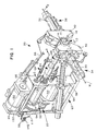
- FIG. 1 is a simplified, fragmentary perspective view of a portion of a double flier armature winding machine provided with quick-change tooling made in accordance with this invention, and also shows a portion of an armature to be wound.
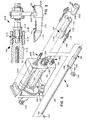
- FIG. 2 is a fragmentary perspective view with parts exploded away of a portion of the machine of FIG. 1 and on a slightly larger scale then FIG. 1. Parts have been removed to better show other parts.
- FIG. 3 is an enlarged, fragmentary side elevational view, with parts in cross section. taken substantially on line 3-3 of FIG. 1.
- FIG. 4 is an enlarged, fragmentary cross-sectional view of a portion of the machine of FIG. 1, and shows, in phantom, a portion of the armature.
- FIG. 5 is an enlarged, fragmentary cross-sectional view of another portion of the machine of FIG. 1.
- FIG. 6 is a cross-sectional view taken along line 6-6 of FIG. 4.
- FIG. 7 is a cross-sectional view taken along line 7-7 of FIG. 5.
- FIG. 8 is a fragmentary cross-sectional view taken along line 8-8 of FIG. 4.
- Referring to FIG. 1, this invention is shown in connection with the winding of an armature, generally designated 10, including an armature core 12 having radially inwardly directed coil-receiving
slots 14 mounted on anarmature shaft 16. Acommutator 18 having plural tangs is mounted upon thesame shaft 16.Armature 10 is merely one example of many armatures that may be wound by a flier-type winder. - A portion of a double flier armature winding machine, generally designated 20, used for winding the
armature 10 is shown in FIG. 1. Only a limited portion of themachine 20 is illustrated because most of the details of construction of themachine 20 may be entirely conventional and are not part of this invention. Briefly,machine 20 includes an armature rotator assembly, generally designated 22, with which are associated commutator shield mechanisms comprising an inner shield assembly, generally designated 24, and an outer shield assembly, generally designated 26. The purpose of thearmature rotator assembly 22 is to position thearmature 10 as required to effect the winding of coils thereon and the connection of coil leads to thecommutator 18, and thearmature rotator assembly 24 has a collet 28 (FIG. 4) for gripping the commutator end of thearmature shaft 16. Examples of prior armature winding machines having armature rotators with collets and commutator shields are shown in U.S. Pat. No. 3,673,878, issued to John M. Biddison on July 4, 1972, and in U.S. Pat. 4,633,577, issued to Alvin C. Banner on Jan. 6, 1987. As will become apparent from the discussion that follows, this invention is directed to improvements in thearmature rotator assembly 22 and in thecommutator shield assemblies - The
armature winding machine 20 further includes left and rightside flier spindles flier assemblies armature 10. A pair of pivotal wire clamp assemblies 38 clamp the free ends of the wires at the end of the winding of one armature until after the commencement of the winding of the next armature. As is well known, during the winding of the armature theflier spindles flier spindles core slots 14. During the winding operations, the wires are guided into thecore slots 14 by left and right side form assemblies 40 and 42. - This invention could be practiced with armature winding machines having any of various types of winding forms. However, this invention is preferably used with other armature-specific tooling devices which can be rapidly changed to accommodate different winding armatures. Winding form assemblies that may be quickly changed are disclosed in U.S. Patent Application Serial No. 125288 titled WINDING FORM ASSEMBLY, filed in the United States Patent and Trademark office on 25th November 1987.
- With reference to FIGS. 1, 2, 4 and 5, the
armature rotator assembly 22 comprises astepping motor 50, which throughgears 52, drives arotator spindle 54 that is hollow to receive acollet release rod 56. Therotator spindle 54 and thecollet release rod 56 are appropriately mounted for rotation within front andrear frame plates frame base plate 64, and aframe top plate 66. Therotator spindle 54 has a reduceddiameter front portion 68 extending through theinner race 70 of abearing 72 in thefront frame plate 58. - Referring to FIGS. 2, 4, and 5, the
collet release rod 56 forms part of a readily removable, modular collet assembly, generally designated 80, which also comprises the aforementioned split collet 28. Split collet 28 includes an armature shaft-gripping, elongated,tubular body portion 82 and an enlarged head 84 having a front collet cam surface 86 and a rear collet cam surface 88. Themodular collet assembly 80 further comprises atubular collet retainer 90 having, at its front end, an inwardly directedflange 92 against which the front collet cam surface 86 bears. Coaxially received within theretainer 90 is atubular collet actuator 94 having afront surface 96 that bears against the rear collet cam surface 88. The rearward end of thecollet actuator 94 is closed by arear wall 98 having a threaded bore to which the threaded forward end portion, designated 98, of thecollet release rod 56 is threadedly connected. -
Collet retainer 90 has an enlarged diameterrearward end portion 102 having, intermediate its ends, an internally threadedbore portion 104 to which a colletretainer end cap 106 is threadedly connected.End cap 106 has a central bore 108 through which the collet release rod extends. The actuatorrear end wall 98 and theretainer end cap 106 define a chamber 110 within the enlarged diameterrear portion 102 of the retainer in which are located plural spring or Bellevillewashers 112. - Because the
release rod 56 is threadedly connected to theend wall 98 of theactuator 94 and theend cap 106 is threadedly connected to theretainer 90, thecollet assembly 80 comprises a unitary subassembly that may be replaced by other collet assemblies for use with armatures having different shaft, commutator, or core configurations. - Further in accordance with this invention, the
collet assembly 80 is assembled with the other parts of thearmature rotator 22 by simple, manually releasable means so that a relatievly unskilled person may assemble and disassemble thecollet assembly 80 on themachine 20 in minimal time. With reference to FIGS. 1, 2, 4, and 5, thecollet assembly 80 may be connected to therotator spindle 54 by first inserting therelease rod 56 into therotator spindle 54 from itsfront end 68 and extending it through the extreme rearward end of therotator spindle 54 as shown in FIG. 5. When fully assembled, as shown in FIG. 4, the rearwardmost end of the enlargedrear end portion 102 of thecollet retainer 90 is slipped over the forwardmost end of the reduced diameterforward portion 68 of therotator spindle 54 extreme forward end of therotator spindle 68. At the same time, the rearwardmost end of therelease rod 56 extends rearwardly through a collet release drive plug 114 mounted in a bearing 116 in aplug housing 118 supported on therear frame plate 60. - The connection between the
collet assembly 80 and the remainder of therotator assembly 22 comprises a pair of disc-like, C-shaped connectors, namely aforward connector 120 and arearward connector 122 shown in FIGS. 2, 4, 5, 6 and 7. Considering first theforward connector 120 shown assembled in FIGS. 4 and 7, it interconnects the forwardmost end of therotator spindle 54 and the rearwardmost end of thecollet retainer 90. For this purpose, the forwardmost end of therotator spindle 54 has a pair of transversely extending, flats orgrooves collet retainer 90 has a pair of transversely extendingslots grooves forward connector 120 may be assembled in thegrooves slots collet retainer 90 releasably fixed, both rotationally and axially, relative to therotator spindle 54. When assembled, the forward C-shapedconnector 120 is prevented from moving out of thegrooves slots forward retaining sleeve 132 slidably mounted on theforward end 68 of therotator spindle 54 between a retainingring 134 trapped in a groove in thespindle 54 and theinner race 70 of thebearing 72. Aspring 136 coiled about the forward portion of therotator spindle 54 biases the retaining sleeve forwardly so that the C-shaped connector cannot accidentally become disengaged. Thespring 136 may be relatively weak so that, for purposes of assembly and disassembly of thecollet assembly 80 to therotator spindle 54 may easily be accomplished by hand. - Considering now the rearward C-shaped
connector 122, it is located in agroove 140 at the extreme rearward end of thecollet release rod 56, and held agaist accidental removal by a rearward retainingsleeve 142 biased into covering relation thereto by acoil spring 144 wrapped around a rearwardly-extendingshank portion 146 of the release drive plug 114. Accidental disassembly of the rearward retainingsleeve 142 is prevented by a retainingring 148 lodged in a groove in theplug shank portion 146. Here it may be noted that, in the operation of thecollet assembly 80, thespring washers 112 bias thecollet actuator 94 against the rear cam surface 88 unless thecollet release rod 56 is driven rearwarly by the release drive plug 114. The release plug 114 is in turn driven rearwardly in known fashion bydowel pins 150 held by adrive link 152 controlled by an colletrelease actuator motor 154 on theframe top plate 66. - With reference to FIGS. 1,2, and 4, the inner
commutator shield assembly 24 of this invention comprises aninner shield 170 havingnotches 172 at its forward end for exposing commutator tangs as now well known in the art. Theinner shield 170 is coaxial with and snugly surrounds thecollet retainer 90 throughout substantially its entire length, and accordingly has an enlargedrear section 174 that receives the enlarged diameterrear portion 102 of thecollet retainer 90.Bushings 176 pressed into the bore of theinner shield 170 provide a bearing between thecollet retainer 90 and theinner shield 170 to permit thecollet retainer 90 to freely rotate relative to theinner shield 170 when driven by thearmarure rotator motor 50. - The
inner shield assembly 24 is connected to thefront frame plate 58 by means permitting a quick change of theinner shield assembly 24. A transverely extendingbracket plate 178 is welded to theinner shield 170 and connected to thefront frame plate 58 by aquick release assembly 180.Quick disconnect assembly 180 comprises a threadedstub shaft 182 threadedly engaged within abore 184 in thefront frame plate 58 to which aquick release coupling 186 having a femaleconnenctor part 188 and amale connector part 190 held together by ball elements (not shown) trapped in a spring biased connector sleeve 192. Here it may be observed that theouter shield assembly 26 has a similarquick release assembly 194 which will be described below.Quick release assembly 194 is shown in cross section in FIG. 3, and that cross section is representative of the corresponding parts of the inner shieldquick release coupling 186. - The end of the
male connector part 188 remote from thefemale connector part 186 extends through an arcuate bore 196 (FIG. 8) in the outer end of thetransverse bracket plate 178. Arcuate bore 196 permits of a limited degree of rotation of theinner shield 170 relative to thebracket plate 178. This enables the machine manufacturer to accurately preset the rotary position of theinner shield 170, and the preset orientation is maintained by a clampingnut asssembly 198. - Referring to FIGS. 1 through 4, the
outer shield assembly 26 comprises a retractableouter shield 200 connected by abracket plate 202 and aquick disconnect assembly 204 to thepiston rod 206 of anair actuator cylinder 208.Quick disconnect assembly 204 includes aquick release coupling 210 comprising afemale connector part 212 and amale connector part 214 held together byball elements 216 trapped in a springbiased connector sleeve 218. The operation of quick release couplings are well known so no further discussion therof is deemed necesasary. - As will be understood by those familiar with the art, this invention enables a machine manufacturer to construct sets of tooling components comprising the quickly removable parts of the inner and outer shield assemblies and the modular collet assemblies. These sets can be tailored to fit individual .armatures and enable the user of the machine to quickly change a machine over from the winding of armatures having one set of parameters to the winding of armatures having a different set of parameters. Because the tooling parts that are not quickly removable have a location fixed relative to the machine frame, the machine manufacturer can readily supply additional tooling sets to the user of the machine whenever needed.
- Although the presently preferred embodiment of this invention has been described, it will be understood that within the purview of this invention various changes may be made within the scope of the appended claims.
Claims (7)
Applications Claiming Priority (2)
| Application Number | Priority Date | Filing Date | Title |
|---|---|---|---|
| US125289 | 1987-11-25 | ||
| US07/125,289 US4915313A (en) | 1987-11-25 | 1987-11-25 | Armature winding machine with quick-change tooling |
Publications (3)
| Publication Number | Publication Date |
|---|---|
| EP0318307A2 true EP0318307A2 (en) | 1989-05-31 |
| EP0318307A3 EP0318307A3 (en) | 1989-12-13 |
| EP0318307B1 EP0318307B1 (en) | 1993-10-27 |
Family
ID=22419006
Family Applications (1)
| Application Number | Title | Priority Date | Filing Date |
|---|---|---|---|
| EP88311173A Expired - Lifetime EP0318307B1 (en) | 1987-11-25 | 1988-11-25 | Armature winding machine with quick-change tooling |
Country Status (4)
| Country | Link |
|---|---|
| US (1) | US4915313A (en) |
| EP (1) | EP0318307B1 (en) |
| JP (1) | JPH01190237A (en) |
| DE (1) | DE3885237T2 (en) |
Cited By (3)
| Publication number | Priority date | Publication date | Assignee | Title |
|---|---|---|---|---|
| US5127594A (en) * | 1990-05-31 | 1992-07-07 | Axis U.S.A., Inc. | Tool changing methods and apparatus for an armature winding machine |
| US5178428A (en) * | 1990-06-18 | 1993-01-12 | Axis Usa, Inc. | Armature gripping machine |
| US5257744A (en) * | 1990-05-31 | 1993-11-02 | Axis Usa, Inc. | Tool changing apparatus for an armature winding machine |
Families Citing this family (5)
| Publication number | Priority date | Publication date | Assignee | Title |
|---|---|---|---|---|
| US6145773A (en) * | 1998-06-23 | 2000-11-14 | Axis Usa, Inc. | Tool changing methods and apparatus for an armature winding machine |
| US6349895B1 (en) * | 1998-11-20 | 2002-02-26 | Axis Usa, Inc. | Changeable flyer |
| DE29919214U1 (en) * | 1999-11-03 | 2000-01-05 | Dewert Antriebs- und Systemtechnik GmbH & Co KG, 32278 Kirchlengern | Electromotive furniture drive |
| CN104753267A (en) * | 2015-03-19 | 2015-07-01 | 深圳市金岷江机电设备有限公司 | Die for winding machine and die closing device for die |
| USD1060658S1 (en) | 2020-12-28 | 2025-02-04 | ResMed Asia Pte. Ltd. | Patient interface |
Family Cites Families (12)
| Publication number | Priority date | Publication date | Assignee | Title |
|---|---|---|---|---|
| US27893A (en) * | 1860-04-17 | David donalds | ||
| US882253A (en) * | 1905-06-12 | 1908-03-17 | Westinghouse Electric & Mfg Co | Coil-winding machine. |
| US2144477A (en) * | 1937-09-28 | 1939-01-17 | Abrams Ralph | Armature winding machine |
| US2348948A (en) * | 1940-07-26 | 1944-05-16 | Gen Motors Corp | Armature for dynamoelectric machines |
| US2969195A (en) * | 1957-03-14 | 1961-01-24 | Cedar Engineering Inc | Coil winding apparatus |
| US3345002A (en) * | 1965-10-24 | 1967-10-03 | Gorski Henry J | Armature winding machine |
| US3673878A (en) * | 1969-12-29 | 1972-07-04 | Globe Tool Eng Co | Shaft rotating mechanism |
| US3785583A (en) * | 1969-12-29 | 1974-01-15 | Globe Tool Eng Co | Shaft rotating mechanism |
| US3927843A (en) * | 1971-04-02 | 1975-12-23 | Possis Corp | Armature winding machine with improved lead retaining means |
| USRE27893E (en) | 1972-04-18 | 1974-01-22 | Armature winding and commutator connection | |
| US4459742A (en) * | 1982-04-15 | 1984-07-17 | The Globe Tool & Engineering Company | Armature winding machine and method |
| US4708297A (en) * | 1985-10-01 | 1987-11-24 | Micafil, Inc. | Armature winding machine with removable collet and shrouds |
-
1987
- 1987-11-25 US US07/125,289 patent/US4915313A/en not_active Expired - Fee Related
-
1988
- 1988-11-25 JP JP63299384A patent/JPH01190237A/en active Pending
- 1988-11-25 EP EP88311173A patent/EP0318307B1/en not_active Expired - Lifetime
- 1988-11-25 DE DE88311173T patent/DE3885237T2/en not_active Expired - Fee Related
Cited By (4)
| Publication number | Priority date | Publication date | Assignee | Title |
|---|---|---|---|---|
| US5127594A (en) * | 1990-05-31 | 1992-07-07 | Axis U.S.A., Inc. | Tool changing methods and apparatus for an armature winding machine |
| EP0459030A3 (en) * | 1990-05-31 | 1993-02-10 | Axis S.P.A. | Tool changing methods and apparatus for an armature winding machine |
| US5257744A (en) * | 1990-05-31 | 1993-11-02 | Axis Usa, Inc. | Tool changing apparatus for an armature winding machine |
| US5178428A (en) * | 1990-06-18 | 1993-01-12 | Axis Usa, Inc. | Armature gripping machine |
Also Published As
| Publication number | Publication date |
|---|---|
| DE3885237T2 (en) | 1994-02-24 |
| US4915313A (en) | 1990-04-10 |
| DE3885237D1 (en) | 1993-12-02 |
| EP0318307A3 (en) | 1989-12-13 |
| EP0318307B1 (en) | 1993-10-27 |
| JPH01190237A (en) | 1989-07-31 |
Similar Documents
| Publication | Publication Date | Title |
|---|---|---|
| EP0318307B1 (en) | Armature winding machine with quick-change tooling | |
| FR2464792A1 (en) | MACHINE TOOL WITH INTERCHANGEABLE TOOLS | |
| EP0484766B1 (en) | Apparatus for facilitating the changing of shrouds in armature winding machines | |
| US4633577A (en) | Armature winding method and apparatus | |
| US4052783A (en) | Apparatus and method for winding armatures | |
| KR101884437B1 (en) | Coil Winding Apparatus | |
| DE102007004550A1 (en) | Sewing machine portal frame shaped to serves as a winding yoke for the bobbin winding process | |
| DE10115449A1 (en) | Filament winding device and yarn finishing process for this device | |
| US4830297A (en) | Winding form assembly | |
| US4827601A (en) | Armature winding method and apparatus | |
| US4974313A (en) | Lead guide actuator mechanism for use on armature winding machines | |
| EP0459030A2 (en) | Tool changing methods and apparatus for an armature winding machine | |
| DE19511420A1 (en) | Rotating clamping device and method for clamping and automatic turning of a workpiece | |
| EP0013086A1 (en) | Power drawbolt with planetary drive | |
| US4289281A (en) | Apparatus for winding armatures | |
| US4174815A (en) | Apparatus for winding armatures | |
| EP0568139B1 (en) | Device for stripping of round wires | |
| US6349895B1 (en) | Changeable flyer | |
| US6314779B1 (en) | Conductor reducer for co-axial cable | |
| US3243130A (en) | Wire wrapping tool | |
| JP4718693B2 (en) | Cutter device for armature winding machine | |
| US5257744A (en) | Tool changing apparatus for an armature winding machine | |
| US4339872A (en) | Apparatus and method for winding armatures | |
| US2167851A (en) | Adjustable spool mounting for wire spooler mechanism | |
| JP3318701B2 (en) | Spindle tool clamping device for machine tools |
Legal Events
| Date | Code | Title | Description |
|---|---|---|---|
| PUAI | Public reference made under article 153(3) epc to a published international application that has entered the european phase |
Free format text: ORIGINAL CODE: 0009012 |
|
| AK | Designated contracting states |
Kind code of ref document: A2 Designated state(s): CH DE FR GB IT LI |
|
| PUAL | Search report despatched |
Free format text: ORIGINAL CODE: 0009013 |
|
| AK | Designated contracting states |
Kind code of ref document: A3 Designated state(s): CH DE FR GB IT LI |
|
| 17P | Request for examination filed |
Effective date: 19900306 |
|
| RAP1 | Party data changed (applicant data changed or rights of an application transferred) |
Owner name: GLOBE PRODUCTS INC. |
|
| 17Q | First examination report despatched |
Effective date: 19920511 |
|
| GRAA | (expected) grant |
Free format text: ORIGINAL CODE: 0009210 |
|
| AK | Designated contracting states |
Kind code of ref document: B1 Designated state(s): CH DE FR GB IT LI |
|
| ITF | It: translation for a ep patent filed | ||
| REF | Corresponds to: |
Ref document number: 3885237 Country of ref document: DE Date of ref document: 19931202 |
|
| ET | Fr: translation filed | ||
| PLBE | No opposition filed within time limit |
Free format text: ORIGINAL CODE: 0009261 |
|
| STAA | Information on the status of an ep patent application or granted ep patent |
Free format text: STATUS: NO OPPOSITION FILED WITHIN TIME LIMIT |
|
| 26N | No opposition filed | ||
| PGFP | Annual fee paid to national office [announced via postgrant information from national office to epo] |
Ref country code: FR Payment date: 19981110 Year of fee payment: 11 |
|
| PGFP | Annual fee paid to national office [announced via postgrant information from national office to epo] |
Ref country code: GB Payment date: 19981127 Year of fee payment: 11 |
|
| PGFP | Annual fee paid to national office [announced via postgrant information from national office to epo] |
Ref country code: DE Payment date: 19981207 Year of fee payment: 11 |
|
| PGFP | Annual fee paid to national office [announced via postgrant information from national office to epo] |
Ref country code: CH Payment date: 19981210 Year of fee payment: 11 |
|
| PG25 | Lapsed in a contracting state [announced via postgrant information from national office to epo] |
Ref country code: GB Free format text: LAPSE BECAUSE OF NON-PAYMENT OF DUE FEES Effective date: 19991125 |
|
| PG25 | Lapsed in a contracting state [announced via postgrant information from national office to epo] |
Ref country code: LI Free format text: LAPSE BECAUSE OF NON-PAYMENT OF DUE FEES Effective date: 19991130 Ref country code: CH Free format text: LAPSE BECAUSE OF NON-PAYMENT OF DUE FEES Effective date: 19991130 |
|
| GBPC | Gb: european patent ceased through non-payment of renewal fee |
Effective date: 19991125 |
|
| REG | Reference to a national code |
Ref country code: CH Ref legal event code: PL |
|
| PG25 | Lapsed in a contracting state [announced via postgrant information from national office to epo] |
Ref country code: FR Free format text: LAPSE BECAUSE OF NON-PAYMENT OF DUE FEES Effective date: 20000731 |
|
| PG25 | Lapsed in a contracting state [announced via postgrant information from national office to epo] |
Ref country code: DE Free format text: LAPSE BECAUSE OF NON-PAYMENT OF DUE FEES Effective date: 20000901 |
|
| REG | Reference to a national code |
Ref country code: FR Ref legal event code: ST |
|
| PG25 | Lapsed in a contracting state [announced via postgrant information from national office to epo] |
Ref country code: IT Free format text: LAPSE BECAUSE OF NON-PAYMENT OF DUE FEES;WARNING: LAPSES OF ITALIAN PATENTS WITH EFFECTIVE DATE BEFORE 2007 MAY HAVE OCCURRED AT ANY TIME BEFORE 2007. THE CORRECT EFFECTIVE DATE MAY BE DIFFERENT FROM THE ONE RECORDED. Effective date: 20051125 |