EP0318380A1 - Modulierendes Gasversorgungstriebwerk für Brenner einer Vorrichtung in der Art eines Gaskessels - Google Patents
Modulierendes Gasversorgungstriebwerk für Brenner einer Vorrichtung in der Art eines Gaskessels Download PDFInfo
- Publication number
- EP0318380A1 EP0318380A1 EP88402950A EP88402950A EP0318380A1 EP 0318380 A1 EP0318380 A1 EP 0318380A1 EP 88402950 A EP88402950 A EP 88402950A EP 88402950 A EP88402950 A EP 88402950A EP 0318380 A1 EP0318380 A1 EP 0318380A1
- Authority
- EP
- European Patent Office
- Prior art keywords
- plate
- opening
- gas
- mechanism according
- orifice
- Prior art date
- Legal status (The legal status is an assumption and is not a legal conclusion. Google has not performed a legal analysis and makes no representation as to the accuracy of the status listed.)
- Granted
Links
- 230000007246 mechanism Effects 0.000 title claims description 23
- 238000009826 distribution Methods 0.000 claims abstract description 8
- 238000007789 sealing Methods 0.000 claims description 5
- 230000010355 oscillation Effects 0.000 claims description 3
- 230000009471 action Effects 0.000 abstract description 3
- 230000000750 progressive effect Effects 0.000 description 7
- 230000008859 change Effects 0.000 description 2
- 238000002485 combustion reaction Methods 0.000 description 2
- 238000004519 manufacturing process Methods 0.000 description 2
- 230000001105 regulatory effect Effects 0.000 description 2
- 230000003247 decreasing effect Effects 0.000 description 1
- 238000005553 drilling Methods 0.000 description 1
- 230000005284 excitation Effects 0.000 description 1
- 238000009432 framing Methods 0.000 description 1
- 230000004048 modification Effects 0.000 description 1
- 238000012986 modification Methods 0.000 description 1
- 235000012771 pancakes Nutrition 0.000 description 1
- 230000002093 peripheral effect Effects 0.000 description 1
- 230000009467 reduction Effects 0.000 description 1
Images
Classifications
-
- F—MECHANICAL ENGINEERING; LIGHTING; HEATING; WEAPONS; BLASTING
- F23—COMBUSTION APPARATUS; COMBUSTION PROCESSES
- F23N—REGULATING OR CONTROLLING COMBUSTION
- F23N1/00—Regulating fuel supply
- F23N1/005—Regulating fuel supply using electrical or electromechanical means
-
- F—MECHANICAL ENGINEERING; LIGHTING; HEATING; WEAPONS; BLASTING
- F16—ENGINEERING ELEMENTS AND UNITS; GENERAL MEASURES FOR PRODUCING AND MAINTAINING EFFECTIVE FUNCTIONING OF MACHINES OR INSTALLATIONS; THERMAL INSULATION IN GENERAL
- F16K—VALVES; TAPS; COCKS; ACTUATING-FLOATS; DEVICES FOR VENTING OR AERATING
- F16K3/00—Gate valves or sliding valves, i.e. cut-off apparatus with closing members having a sliding movement along the seat for opening and closing
- F16K3/30—Details
- F16K3/34—Arrangements for modifying the way in which the rate of flow varies during the actuation of the valve
-
- F—MECHANICAL ENGINEERING; LIGHTING; HEATING; WEAPONS; BLASTING
- F23—COMBUSTION APPARATUS; COMBUSTION PROCESSES
- F23N—REGULATING OR CONTROLLING COMBUSTION
- F23N2227/00—Ignition or checking
- F23N2227/20—Calibrating devices
-
- F—MECHANICAL ENGINEERING; LIGHTING; HEATING; WEAPONS; BLASTING
- F23—COMBUSTION APPARATUS; COMBUSTION PROCESSES
- F23N—REGULATING OR CONTROLLING COMBUSTION
- F23N2235/00—Valves, nozzles or pumps
- F23N2235/02—Air or combustion gas valves or dampers
- F23N2235/10—Air or combustion gas valves or dampers power assisted, e.g. using electric motors
-
- F—MECHANICAL ENGINEERING; LIGHTING; HEATING; WEAPONS; BLASTING
- F23—COMBUSTION APPARATUS; COMBUSTION PROCESSES
- F23N—REGULATING OR CONTROLLING COMBUSTION
- F23N2235/00—Valves, nozzles or pumps
- F23N2235/12—Fuel valves
- F23N2235/18—Groups of two or more valves
-
- F—MECHANICAL ENGINEERING; LIGHTING; HEATING; WEAPONS; BLASTING
- F23—COMBUSTION APPARATUS; COMBUSTION PROCESSES
- F23N—REGULATING OR CONTROLLING COMBUSTION
- F23N2235/00—Valves, nozzles or pumps
- F23N2235/12—Fuel valves
- F23N2235/24—Valve details
Definitions
- the invention which relates to apparatuses of the gas boiler type relates more precisely to a mechanism which allows a modular supply of gas to the burner of the apparatus using a rotary plate provided with a plurality of calibrated injectors.
- the gas supply to the burner of a boiler is carried out in the usual way using an electrovalve, the shutter valve of which is associated with a core or a movable magnetic paddle.
- the opening or closing of the valve is ensured by the attraction of the movable core or the pallet which abruptly comes to sticking against a fixed core as soon as a current is supplied to the coil of the solenoid valve.
- This type of simplified solenoid valve operating in "all or nothing" has been replaced more and more often now by the solenoid valve with progressive opening which makes it possible to obtain, from a first opening threshold corresponding to a determined flow, a progressive increase in the gas intake, directly controlled by the intensity of the excitation current of the solenoid valve coil.
- the shutter assembly consists of two concentric valves, a small flow valve being directly integral with the movable core of the coil.
- the core has a cylindrical extension which engages in a central orifice of a large flow valve whose opening profile is progressive and which carries a system of stop and drive plate thanks to which it can, from an intensity threshold, applied to the coil, open this high flow valve so that the gas passage orifice is progressive and subject to variations in intensity.
- This solenoid valve or similar type of solenoid valves are operated in the usual way, and work properly, but nevertheless have a number of drawbacks.
- you want to change the minimum power of the device or adjust the minimum gas flow depending on the type of gas used you must replace at least some parts of the solenoid valve and proceed with disassembly and reassembly operations long.
- the precision of the intake gas flow rate is directly linked to the precision of the progressive opening of the profiled valve, and it is therefore very sensitive to the dimensional variations of the valve, and to its adjustment.
- the invention therefore relates to a modular gas supply mechanism to the burner of an appliance of the type of a gas boiler reacting to an intensity of electric current supplied by a command and regulation device in view to control the flow of gas admitted to the burner to this current as a function of the demand for calories, a mechanism according to which a rotary plate is arranged inside a closed chamber in which gas is admitted at normal pressure, and which the gas can exit through an opening towards the burners and according to which said plate carries a plurality of calibrated orifices traversing it over its entire thickness and distributed over at least one ring of the plate, at right of the opening, at least one part of the plate in line with said opening being provided with a means ensuring its closing, mechanism according to which also said plate is mounted in the chamber to be applied against the opening and is driven in rotation in a manner n motorized from a position where it closes the opening, at least one position corresponding to a determined intensity in which a calibrated orifice is located opposite the opening and releases a flow of gas suitable for the burners
- the turntable is housed in a distribution box having a gas inlet opening, a gas inlet box being applied against the box to communicate an inlet chamber with said opening.
- the orifices carried by the plate are calibrated differently and progressively from one to the other, between an orifice of minimum diameter and an orifice of maximum diameter, the drive of the plate being ensured by a stepping motor acting on its axis.
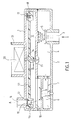
- the mechanism shown in FIG. 1 essentially comprises a first gas intake box 2 which is associated with a second gas distribution box towards the burners, the second box being designated as a whole by the reference 1.
- the box 1 which appears as a circular-shaped pancake has, at its lower part with a gas inlet opening 10 and near its peripheral edge, on its upper part, with a gas starting opening 11 towards the burners not shown.
- the periphery of the starting opening 11, on the internal face of the housing 1 is in relief with respect to said housing in order to form a rod 22 for a sealing member, as will be seen below.
- the intake box 2 has the shape of a shell which is applied in a sealed manner against the underside of the box 1.
- a gas inlet orifice 3 allows the entry of gas into an intake chamber 4 during the opening of a stop valve 5.
- the chamber 4 communicates with the pressure chamber 6 of a gas flow regulator whose diaphragm 7 with adjustable return acts on a regulating valve 8 which opens more or minus a passage orifice 9. The latter is superimposed on the inlet opening 10 of the distribution box.
- Said distribution box 1 when the valve 5 is open sees its inner chamber 12 filled with gas at the inlet pressure. Inside this circular chamber is mounted a rotary plate 13 whose axis of rotation 14 extends vertically between the two opposite faces forming the bottom and the cover of the housing 1, on which it bears in the center of the housing. The plate is mounted on the axis 14 so that its upper face is supported on the seat 22. A spiral spring 15 is interposed on the axis between the bottom of the housing and the lower face of the plate 13; one of its ends is anchored to the housing, the other is anchored to the tray itself. The axis 14 sealingly crosses the cover of the housing 1 and is connected to a stepping motor 20 fixedly mounted in a cell 21 outside the housing.
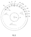
- the plate 13 also represented in FIG. 2, presents over its entire periphery a succession of orifices 16 (16a, 16b, 16c ... 16g) which are calibrated differently and progressively from an orifice to the orifice neighboring between an orifice 16a minimum diameter and an orifice 16 n maximum diameter.
- an annular ring 19 is provided serving as a friction part against the seat 22 and thus ensuring the sealing of the chamber 12 between the outlet opening 11 and the orifice 16 carried by the plate 13.
- valve 17 In one place of the plate 13, there is no orifice but a small shutter valve 17 above the plate, slidably mounted on a small support rod perpendicular to the plane of the plate, a small spring return 18 being interposed between said valve 17 and the plate.
- the valve 17 is located between the orifice 16a more small diameter, and the orifice 16 n of larger diameter, said orifices framing the valve.
- the valve 17 could be constituted by a simple fixed range of the plate, possibly with an additional thickness or an added sealing part.
- the orifices 16 are obtained directly by drilling in the plate or else they consist of a series of injectors with variable orifices mounted in sealed manner in identical openings in the plate.
- gas injectors are for example those already used in conventional devices, which thus introduces a simplification in the production of the device.
- valve 5 When there is no demand for calories from the appliance, but it is ready to operate, the valve 5 is open and the gas is admitted to its supply pressure, in chamber 12.
- the tray 13 then occupies a position for which the shutter valve 17 is opposite the opening 11 and applied against the seat 22 under the action of its small return spring 18, and the gas cannot exit in the direction of the burners.
- the mechanism After operation, when the motor 20 is no longer stressed, the mechanism is reset to zero by returning the plate 13 to its original position under the action of the spiral spring 15, position for which the valve 17 closes the opening 11 .
- the mechanism thus described is simple to carry out.
- the plate 13 can be molded or stamped sheet.
- the seals at the opening 11, thanks to the crown 19 are easy to produce. Once the tray is mounted, no further adjustment is required.
Landscapes
- Engineering & Computer Science (AREA)
- General Engineering & Computer Science (AREA)
- Mechanical Engineering (AREA)
- Chemical & Material Sciences (AREA)
- Combustion & Propulsion (AREA)
- Feeding And Controlling Fuel (AREA)
- Electrically Driven Valve-Operating Means (AREA)
Applications Claiming Priority (2)
| Application Number | Priority Date | Filing Date | Title |
|---|---|---|---|
| FR8716453A FR2623880B1 (fr) | 1987-11-27 | 1987-11-27 | Mecanisme d'alimentation modulable du gaz au bruleur d'un appareil du genre chaudiere a gaz |
| FR8716453 | 1987-11-27 |
Publications (2)
| Publication Number | Publication Date |
|---|---|
| EP0318380A1 true EP0318380A1 (de) | 1989-05-31 |
| EP0318380B1 EP0318380B1 (de) | 1992-09-02 |
Family
ID=9357234
Family Applications (1)
| Application Number | Title | Priority Date | Filing Date |
|---|---|---|---|
| EP88402950A Expired - Lifetime EP0318380B1 (de) | 1987-11-27 | 1988-11-24 | Modulierendes Gasversorgungstriebwerk für Brenner einer Vorrichtung in der Art eines Gaskessels |
Country Status (4)
| Country | Link |
|---|---|
| EP (1) | EP0318380B1 (de) |
| DE (1) | DE3874296T2 (de) |
| ES (1) | ES2034333T3 (de) |
| FR (1) | FR2623880B1 (de) |
Cited By (2)
| Publication number | Priority date | Publication date | Assignee | Title |
|---|---|---|---|---|
| EP0915295A3 (de) * | 1997-11-04 | 1999-09-29 | Miele & Cie. GmbH & Co. | Gasbeheiztes Gerät mit einer Einrichtung zur Regelung des Heizbetriebes |
| FR2786243A1 (fr) * | 1998-11-23 | 2000-05-26 | Sdecc | Dispositif d'etancheite du moteur pas a pas de commande d'admission du gaz au bruleur d'un chauffe-bains ou d'une chaudiere, et procede pour la realisation du dispositif |
Families Citing this family (3)
| Publication number | Priority date | Publication date | Assignee | Title |
|---|---|---|---|---|
| EP2457023B1 (de) * | 2009-07-24 | 2016-09-07 | BSH Hausgeräte GmbH | Gasventileinheit für einen gasbrenner |
| DE102010039009A1 (de) * | 2010-08-06 | 2012-02-09 | BSH Bosch und Siemens Hausgeräte GmbH | Gasventileinheit |
| AU2011304473B2 (en) * | 2010-09-20 | 2014-10-09 | Bsh Hausgerate Gmbh | Structure of a gas-valve unit |
Citations (6)
| Publication number | Priority date | Publication date | Assignee | Title |
|---|---|---|---|---|
| US1379904A (en) * | 1916-12-20 | 1921-05-31 | John H Derby | Pressure-reducing valve |
| FR1180167A (fr) * | 1957-07-26 | 1959-06-02 | Porcelaines Electrotechniques | Perfectionnements apportés aux vannes et leurs applications |
| US3014489A (en) * | 1958-03-17 | 1961-12-26 | Whirlpool Co | Gas valve |
| DE3047136A1 (de) * | 1980-12-15 | 1982-06-16 | Danfoss A/S, 6430 Nordborg | "schieberventil" |
| US4643215A (en) * | 1985-07-19 | 1987-02-17 | Essex Industries, Inc. | Gas flow control valve |
| EP0245068A2 (de) * | 1986-05-08 | 1987-11-11 | Matsushita Electric Industrial Co., Ltd. | Steuergerät für eine Gasströmung |
Family Cites Families (1)
| Publication number | Priority date | Publication date | Assignee | Title |
|---|---|---|---|---|
| FR2249275B1 (de) * | 1973-10-25 | 1977-09-09 | Saunier Duval |
-
1987
- 1987-11-27 FR FR8716453A patent/FR2623880B1/fr not_active Expired - Fee Related
-
1988
- 1988-11-24 ES ES198888402950T patent/ES2034333T3/es not_active Expired - Lifetime
- 1988-11-24 DE DE8888402950T patent/DE3874296T2/de not_active Expired - Fee Related
- 1988-11-24 EP EP88402950A patent/EP0318380B1/de not_active Expired - Lifetime
Patent Citations (6)
| Publication number | Priority date | Publication date | Assignee | Title |
|---|---|---|---|---|
| US1379904A (en) * | 1916-12-20 | 1921-05-31 | John H Derby | Pressure-reducing valve |
| FR1180167A (fr) * | 1957-07-26 | 1959-06-02 | Porcelaines Electrotechniques | Perfectionnements apportés aux vannes et leurs applications |
| US3014489A (en) * | 1958-03-17 | 1961-12-26 | Whirlpool Co | Gas valve |
| DE3047136A1 (de) * | 1980-12-15 | 1982-06-16 | Danfoss A/S, 6430 Nordborg | "schieberventil" |
| US4643215A (en) * | 1985-07-19 | 1987-02-17 | Essex Industries, Inc. | Gas flow control valve |
| EP0245068A2 (de) * | 1986-05-08 | 1987-11-11 | Matsushita Electric Industrial Co., Ltd. | Steuergerät für eine Gasströmung |
Cited By (3)
| Publication number | Priority date | Publication date | Assignee | Title |
|---|---|---|---|---|
| EP0915295A3 (de) * | 1997-11-04 | 1999-09-29 | Miele & Cie. GmbH & Co. | Gasbeheiztes Gerät mit einer Einrichtung zur Regelung des Heizbetriebes |
| FR2786243A1 (fr) * | 1998-11-23 | 2000-05-26 | Sdecc | Dispositif d'etancheite du moteur pas a pas de commande d'admission du gaz au bruleur d'un chauffe-bains ou d'une chaudiere, et procede pour la realisation du dispositif |
| EP1004802A1 (de) * | 1998-11-23 | 2000-05-31 | SAUNIER DUVAL EAU CHAUDE CHAUFFAGE S.D.E.C.C. - Société anonyme | Vorrichtung zum Abdichten des Gaszufuhr-Schrittmotors eines Brenners für Baderhitzer oder Heizkessel und Verfahren zur Herstellung der Vorrichtung |
Also Published As
| Publication number | Publication date |
|---|---|
| FR2623880A1 (fr) | 1989-06-02 |
| FR2623880B1 (fr) | 1990-04-27 |
| EP0318380B1 (de) | 1992-09-02 |
| DE3874296D1 (de) | 1992-10-08 |
| DE3874296T2 (de) | 1993-03-25 |
| ES2034333T3 (es) | 1993-04-01 |
Similar Documents
| Publication | Publication Date | Title |
|---|---|---|
| EP0277055B1 (de) | Elektrisches Mikro-Umschaltventil mit einer einzigen Membran | |
| FR2694365A1 (fr) | Vanne à écoulement proprotionnel. | |
| FR2586784A1 (fr) | Robinetterie melangeuse sanitaire | |
| FR2702943A1 (fr) | Machïne à boisson chaude pourvue d'un dispositif de variation du goût de la boisson. | |
| FR2781529A1 (fr) | Injecteur de carburant equipe d'une soupape de commande amont et procede de realisation | |
| EP1669648B1 (de) | Motorgesteuertes Ventil | |
| FR2574117A1 (fr) | Valve a tiroir pivotant pour reguler le debit d'un fluide en fonction de la temperature | |
| EP1844686A1 (de) | Druckkochgerät mit überwachter Dekompression | |
| EP0028049A1 (de) | Steuervorrichtung für ein Wasseraufbereitungssystem | |
| EP0318380B1 (de) | Modulierendes Gasversorgungstriebwerk für Brenner einer Vorrichtung in der Art eines Gaskessels | |
| CA1122111A (fr) | Dispositifs de securite et de commande pour appareils de production instantanee d'eau chaude par le gaz fonctionnant sans veilleuse permanente | |
| FR2610373A1 (fr) | Appareil de conditionnement d'un carburant liquide | |
| FR2697320A1 (fr) | Brûleur à gaz extra-plat à système de sécurité destiné particulièrement aux appareils à cuisiner à usage domestique. | |
| EP0622040B1 (de) | Elektrische Kaffeemaschine | |
| EP3890564B1 (de) | Dampfkocherzubehör mit doppelter turbokrone | |
| EP0196273B1 (de) | Elektromagnetisches Ventil mit mehreren Durchflussmengen | |
| EP0005395A1 (de) | Vorrichtung zur Regulierung der kleinen Durchströmung eines Elektromagnetventils einer Einrichtung der Bauart eines Kessels mit Gasfeuerung | |
| FR2518693A1 (fr) | Electrovalve a ouverture progressive pour la commande et la regulation de l'arrivee du gaz a un bruleur | |
| FR2639422A1 (fr) | Rampe d'injection de gaz pour bruleur sequentiel de chaudiere a gaz a puissance variable | |
| EP0452234B1 (de) | Elektrisch gesteuertes Ventil mit variablem Durchfluss | |
| FR2552848A1 (fr) | Dispositif hydraulique assurant l'ouverture et la fermeture brusque d'un clapet d'arrivee de gaz a un bruleur de chauffe-eau ou chauffe-bains instantane a gaz | |
| EP0064725A1 (de) | Gasbrenner, insbesondere zum Kochen bei niedriger Temperatur | |
| EP1939505B1 (de) | Gaszufuhrhahn | |
| EP0442777B1 (de) | Durchflussregler mit einer durch Druckdifferenz betätigten Membran für ein Heisswasser-Gerät | |
| FR2588935A1 (fr) | Electrovane constituee de modules juxtaposes |
Legal Events
| Date | Code | Title | Description |
|---|---|---|---|
| PUAI | Public reference made under article 153(3) epc to a published international application that has entered the european phase |
Free format text: ORIGINAL CODE: 0009012 |
|
| AK | Designated contracting states |
Kind code of ref document: A1 Designated state(s): BE DE ES GB IT |
|
| 17P | Request for examination filed |
Effective date: 19891108 |
|
| 17Q | First examination report despatched |
Effective date: 19910219 |
|
| GRAA | (expected) grant |
Free format text: ORIGINAL CODE: 0009210 |
|
| AK | Designated contracting states |
Kind code of ref document: B1 Designated state(s): BE DE ES GB IT |
|
| REF | Corresponds to: |
Ref document number: 3874296 Country of ref document: DE Date of ref document: 19921008 |
|
| GBT | Gb: translation of ep patent filed (gb section 77(6)(a)/1977) | ||
| ITF | It: translation for a ep patent filed | ||
| REG | Reference to a national code |
Ref country code: ES Ref legal event code: FG2A Ref document number: 2034333 Country of ref document: ES Kind code of ref document: T3 |
|
| PLBE | No opposition filed within time limit |
Free format text: ORIGINAL CODE: 0009261 |
|
| STAA | Information on the status of an ep patent application or granted ep patent |
Free format text: STATUS: NO OPPOSITION FILED WITHIN TIME LIMIT |
|
| 26N | No opposition filed | ||
| PGFP | Annual fee paid to national office [announced via postgrant information from national office to epo] |
Ref country code: DE Payment date: 19951114 Year of fee payment: 8 |
|
| PGFP | Annual fee paid to national office [announced via postgrant information from national office to epo] |
Ref country code: GB Payment date: 19951115 Year of fee payment: 8 |
|
| PGFP | Annual fee paid to national office [announced via postgrant information from national office to epo] |
Ref country code: BE Payment date: 19951120 Year of fee payment: 8 |
|
| PGFP | Annual fee paid to national office [announced via postgrant information from national office to epo] |
Ref country code: ES Payment date: 19951123 Year of fee payment: 8 |
|
| PG25 | Lapsed in a contracting state [announced via postgrant information from national office to epo] |
Ref country code: GB Effective date: 19961124 |
|
| PG25 | Lapsed in a contracting state [announced via postgrant information from national office to epo] |
Ref country code: ES Free format text: LAPSE BECAUSE OF NON-PAYMENT OF DUE FEES Effective date: 19961125 |
|
| PG25 | Lapsed in a contracting state [announced via postgrant information from national office to epo] |
Ref country code: BE Effective date: 19961130 |
|
| BERE | Be: lapsed |
Owner name: S.A. SAUNIER DUVAL EAU CHAUDE CHAUFFAGE SDECC Effective date: 19961130 |
|
| GBPC | Gb: european patent ceased through non-payment of renewal fee |
Effective date: 19961124 |
|
| PG25 | Lapsed in a contracting state [announced via postgrant information from national office to epo] |
Ref country code: DE Effective date: 19970801 |
|
| REG | Reference to a national code |
Ref country code: ES Ref legal event code: FD2A Effective date: 19971213 |
|
| PG25 | Lapsed in a contracting state [announced via postgrant information from national office to epo] |
Ref country code: IT Free format text: LAPSE BECAUSE OF NON-PAYMENT OF DUE FEES Effective date: 20051124 |