EP0318388A1 - Vorrichtung zur Messung einer Flüssigkeitsströmung in einem Leitungsrohr - Google Patents
Vorrichtung zur Messung einer Flüssigkeitsströmung in einem Leitungsrohr Download PDFInfo
- Publication number
- EP0318388A1 EP0318388A1 EP88402960A EP88402960A EP0318388A1 EP 0318388 A1 EP0318388 A1 EP 0318388A1 EP 88402960 A EP88402960 A EP 88402960A EP 88402960 A EP88402960 A EP 88402960A EP 0318388 A1 EP0318388 A1 EP 0318388A1
- Authority
- EP
- European Patent Office
- Prior art keywords
- heating element
- flow rate
- flow
- sensor
- fluid
- Prior art date
- Legal status (The legal status is an assumption and is not a legal conclusion. Google has not performed a legal analysis and makes no representation as to the accuracy of the status listed.)
- Withdrawn
Links
Images

Classifications
-
- G—PHYSICS
- G01—MEASURING; TESTING
- G01F—MEASURING VOLUME, VOLUME FLOW, MASS FLOW OR LIQUID LEVEL; METERING BY VOLUME
- G01F1/00—Measuring the volume flow or mass flow of fluid or fluent solid material wherein the fluid passes through a meter in a continuous flow
- G01F1/704—Measuring the volume flow or mass flow of fluid or fluent solid material wherein the fluid passes through a meter in a continuous flow using marked regions or existing inhomogeneities within the fluid stream, e.g. statistically occurring variations in a fluid parameter
- G01F1/708—Measuring the time taken to traverse a fixed distance
- G01F1/7084—Measuring the time taken to traverse a fixed distance using thermal detecting arrangements
-
- G—PHYSICS
- G01—MEASURING; TESTING
- G01F—MEASURING VOLUME, VOLUME FLOW, MASS FLOW OR LIQUID LEVEL; METERING BY VOLUME
- G01F1/00—Measuring the volume flow or mass flow of fluid or fluent solid material wherein the fluid passes through a meter in a continuous flow
- G01F1/704—Measuring the volume flow or mass flow of fluid or fluent solid material wherein the fluid passes through a meter in a continuous flow using marked regions or existing inhomogeneities within the fluid stream, e.g. statistically occurring variations in a fluid parameter
- G01F1/708—Measuring the time taken to traverse a fixed distance
- G01F1/712—Measuring the time taken to traverse a fixed distance using auto-correlation or cross-correlation detection means
-
- G—PHYSICS
- G01—MEASURING; TESTING
- G01P—MEASURING LINEAR OR ANGULAR SPEED, ACCELERATION, DECELERATION, OR SHOCK; INDICATING PRESENCE, ABSENCE, OR DIRECTION, OF MOVEMENT
- G01P5/00—Measuring speed of fluids, e.g. of air stream; Measuring speed of bodies relative to fluids, e.g. of ship, of aircraft
- G01P5/18—Measuring speed of fluids, e.g. of air stream; Measuring speed of bodies relative to fluids, e.g. of ship, of aircraft by measuring the time taken to traverse a fixed distance
Definitions
- the present invention relates to a device for measuring a fluid flow rate in a pipeline.
- thermal flowmeters include a heat source intended to locally increase the temperature of a fluid circulating in a pipe and temperature sensors making it possible to measure this increase in order to deduce the flow rate therefrom.
- the present invention aims to provide a device for carrying out such a measurement without intervention on the pipe itself.
- the subject of the invention is a device for measuring a flow rate of fluid in a pipe, characterized in that it comprises a heating element such as a collar and at least one temperature sensor, such a wire probe arranged to be arranged around the pipe, means for applying to said heating element a predetermined electrical power, and means for determining the flow rate in the pipe from the signal transmitted by the sensor.
- a heating element such as a collar and at least one temperature sensor, such a wire probe arranged to be arranged around the pipe, means for applying to said heating element a predetermined electrical power, and means for determining the flow rate in the pipe from the signal transmitted by the sensor.
- Both the heat source, namely the heating element, and the temperature sensors are therefore arranged outside the pipe around the latter, so that the device according to the invention can be instantly adapted to any existing pipeline.
- said predetermined power is applied for a limited period, the device comprising a single sensor, and means for determining the maximum of the signal transmitted by the sensor.
- said predetermined power is also applied for a limited period, the device still comprising only one sensor, but the means for determining the flow rate comprise means for determining the phase shift between the entry into power of the heating element and the signal transmitted by the sensor.
- This phase shift can in particular be determined using means making it possible to calculate the maximum of the intercorrelation function between the input of the heating element and the signal transmitted by the sensor.
- said predetermined power is a periodic power
- the device then comprising two sensors and means for determining the phase difference between the signals transmitted by the two sensors.
- These means for determining the phase shift can then comprise means making it possible to calculate the maximum of the intercorrelation function between the signals transmitted by the two sensors.
- the flow can then be determined according to the case from this phase shift, or from the maximum temperature rise, either directly by calculation, or using a calibration curve, previously stored.
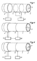
- FIG. 1 represents a pipe 1 in which a fluid 2 circulates in the direction of arrow 3.
- a heating collar 4 is placed around the pipe, and connected to a function generator 5.
- Two son probes 6 and 7 are also arranged around the pipe downstream from the collar 4, and their outputs are connected to a computing unit 8.
- the probe 6 can be placed at a distance of the order of 5 to 10 cm from the axis of the collar 4, and the probe 7 at a distance of the order of 10 to 20 cm.
- the function generator applies periodic power to the collar 4, for example a square signal with a period equal to 60 seconds for a power of 150 watts.
- the measurements carried out by the probes 6 and 7 start after the stabilization of the regime, which occurs after a few periods, and are separated by a time interval dt equal for example to 0.2 seconds.
- the signals transmitted by the two probes are then smoothed, and the unit 8 calculates the phase difference between the temperatures measured by the two probes, for example by the maximum of the intercorrelation function: where s1 or s2 are the signals transmitted by probes 6 and 7.
- the flow rate can be determined from the phase shift anyway using a calibration curve.
- a single wire probe 9 is used, arranged for example at a distance of about 5 cm from the collar 4, and connected to a calculation unit 10 to which the generator is also connected function 5.
- a single power window is applied to the collar 4, for example 150 watts for a period of 30 seconds.
- a measurement using the probe 9 is carried out for example every 0.2 seconds, starting from the start of the slot.
- the unit 10 calculates the phase difference between the power input in the collar 4 and the temperature measured by the probe 9.
- the flow rate is then determined from this phase shift using a calibration curve which can be stored in the calculation unit 10.
- FIG. 6 shows such a curve representing the phase shift ⁇ t as a function of the flow rate D, for a flow rate of up to 800 liters per hour.
- the probe 9 is alone connected to a calculation unit 11.
- a slot of 150 watts is applied to the collar 4 for 30 seconds. Measurements are also made, for example, every 0.2 seconds and start from the start of the slot.
- FIG. 4 represents the rise in temperature ⁇ as a function of time.
- This curve has a maximum ⁇ M and it has been found that the value of this maximum ⁇ M is directly linked to the flow rate in the pipeline.
- the calculation unit 11 can therefore, after having noted this maximum ⁇ M , deduce the flow rate D therefrom, using a calibration curve such as that of FIG. 5, which represents the value of the maximum ⁇ M , depending on the flow rate for a flow rate varying up to 2,000 liters per hour.
Landscapes
- Physics & Mathematics (AREA)
- General Physics & Mathematics (AREA)
- Fluid Mechanics (AREA)
- Engineering & Computer Science (AREA)
- Aviation & Aerospace Engineering (AREA)
- Measuring Volume Flow (AREA)
Applications Claiming Priority (2)
| Application Number | Priority Date | Filing Date | Title |
|---|---|---|---|
| FR8716268 | 1987-11-24 | ||
| FR8716268A FR2623617B1 (fr) | 1987-11-24 | 1987-11-24 | Dispositif pour la mesure d'un debit de fluide dans une canalisation |
Publications (1)
| Publication Number | Publication Date |
|---|---|
| EP0318388A1 true EP0318388A1 (de) | 1989-05-31 |
Family
ID=9357102
Family Applications (1)
| Application Number | Title | Priority Date | Filing Date |
|---|---|---|---|
| EP88402960A Withdrawn EP0318388A1 (de) | 1987-11-24 | 1988-11-24 | Vorrichtung zur Messung einer Flüssigkeitsströmung in einem Leitungsrohr |
Country Status (2)
| Country | Link |
|---|---|
| EP (1) | EP0318388A1 (de) |
| FR (1) | FR2623617B1 (de) |
Cited By (6)
| Publication number | Priority date | Publication date | Assignee | Title |
|---|---|---|---|---|
| US5026171A (en) * | 1989-06-07 | 1991-06-25 | Feller Murray F | Apparatus for flow rate and energy transfer measurements |
| US5333674A (en) * | 1990-09-14 | 1994-08-02 | Taprogge Gmbh | Method for measuring the cleaning effectiveness of cleaning bodies on heat exchangers |
| US6193787B1 (en) | 1996-09-16 | 2001-02-27 | Notetry Limited | Domestic vacuum cleaner and an attachment therefor |
| WO2001098738A3 (en) * | 2000-06-23 | 2002-03-28 | Michael Bowling | Fluid flow measurements |
| DE19521786B4 (de) * | 1994-06-21 | 2007-02-01 | Institut Français du Pétrole, Rueil-Malmaison | Verfahren und Vorrichtung zum Überwachen eines Partikelstromes in einer Leitung durch periodische Erregung |
| US10159213B2 (en) | 2016-04-13 | 2018-12-25 | Beco Dairy Automation Inc. | Fluid measurement device and methods of making and using the same |
Citations (6)
| Publication number | Priority date | Publication date | Assignee | Title |
|---|---|---|---|---|
| NL83702C (de) * | 1946-05-21 | 1900-01-01 | ||
| DE2934566A1 (de) * | 1979-08-27 | 1981-03-19 | Siemens AG, 1000 Berlin und 8000 München | Thermische messvorrichtung zur bestimmung von stroemungsgeschwindigkiten eines fliessenden mediums |
| FR2471593A1 (fr) * | 1979-12-13 | 1981-06-19 | Sacre Louis | Dispositif pour la pesee des avions |
| JPS59147271A (ja) * | 1983-02-14 | 1984-08-23 | Fuji Electric Co Ltd | 相関式速度測定装置 |
| FR2600776A1 (fr) * | 1986-06-24 | 1987-12-31 | Novatome | Dispositif de mesure de la vitesse d'un metal liquide en circulation a faible vitesse dans un conduit |
| FR2607250A1 (fr) * | 1986-11-25 | 1988-05-27 | Schlumberger Cie Dowell | Debitmetre pour fluides dielectriques, a intercorrelation sur bruit triboelectrique et applications notamment aux fluides du secteur petrolier |
-
1987
- 1987-11-24 FR FR8716268A patent/FR2623617B1/fr not_active Expired - Lifetime
-
1988
- 1988-11-24 EP EP88402960A patent/EP0318388A1/de not_active Withdrawn
Patent Citations (6)
| Publication number | Priority date | Publication date | Assignee | Title |
|---|---|---|---|---|
| NL83702C (de) * | 1946-05-21 | 1900-01-01 | ||
| DE2934566A1 (de) * | 1979-08-27 | 1981-03-19 | Siemens AG, 1000 Berlin und 8000 München | Thermische messvorrichtung zur bestimmung von stroemungsgeschwindigkiten eines fliessenden mediums |
| FR2471593A1 (fr) * | 1979-12-13 | 1981-06-19 | Sacre Louis | Dispositif pour la pesee des avions |
| JPS59147271A (ja) * | 1983-02-14 | 1984-08-23 | Fuji Electric Co Ltd | 相関式速度測定装置 |
| FR2600776A1 (fr) * | 1986-06-24 | 1987-12-31 | Novatome | Dispositif de mesure de la vitesse d'un metal liquide en circulation a faible vitesse dans un conduit |
| FR2607250A1 (fr) * | 1986-11-25 | 1988-05-27 | Schlumberger Cie Dowell | Debitmetre pour fluides dielectriques, a intercorrelation sur bruit triboelectrique et applications notamment aux fluides du secteur petrolier |
Non-Patent Citations (2)
| Title |
|---|
| K.D. TIMMERHAUS: " Advances in cryogenic engineering", vol. 23, Proceedings of the 1977 Cryogenic Engineering Conference, Colorado, 2-5 août 1977, pages 391-396, Plenum Press, New York, US; O. TSUKAMOTO et al.: "Determination of the flow velocity of cryogenic fluid by use of a correlation technique" * |
| PATENT ABSTRACTS OF JAPAN, vol. 8, no. 282 (P-323)[1719], 22 décembre 1984, page 72 P 323; & JP-A-59 147 271 (FUJI DENKI SEIZO K.K.) 23-08-1984 * |
Cited By (7)
| Publication number | Priority date | Publication date | Assignee | Title |
|---|---|---|---|---|
| US5026171A (en) * | 1989-06-07 | 1991-06-25 | Feller Murray F | Apparatus for flow rate and energy transfer measurements |
| US5333674A (en) * | 1990-09-14 | 1994-08-02 | Taprogge Gmbh | Method for measuring the cleaning effectiveness of cleaning bodies on heat exchangers |
| DE19521786B4 (de) * | 1994-06-21 | 2007-02-01 | Institut Français du Pétrole, Rueil-Malmaison | Verfahren und Vorrichtung zum Überwachen eines Partikelstromes in einer Leitung durch periodische Erregung |
| US6193787B1 (en) | 1996-09-16 | 2001-02-27 | Notetry Limited | Domestic vacuum cleaner and an attachment therefor |
| WO2001098738A3 (en) * | 2000-06-23 | 2002-03-28 | Michael Bowling | Fluid flow measurements |
| US10159213B2 (en) | 2016-04-13 | 2018-12-25 | Beco Dairy Automation Inc. | Fluid measurement device and methods of making and using the same |
| US11439116B1 (en) | 2016-04-13 | 2022-09-13 | Beco Dairy Automation Inc. | Fluid measurement device and methods of making and using the same |
Also Published As
| Publication number | Publication date |
|---|---|
| FR2623617B1 (fr) | 1991-06-07 |
| FR2623617A1 (fr) | 1989-05-26 |
Similar Documents
| Publication | Publication Date | Title |
|---|---|---|
| EP3087361B1 (de) | Vorrichtung zum lesen und senden von gemessenen temperaturwerten | |
| FR2488406A1 (fr) | Procede et instrument de mesure de corrosion a compensation de temperature secondaire | |
| FR2539873A1 (fr) | Thermometre clinique electronique a reponse rapide | |
| FR2552876A1 (fr) | Systeme thermique de mesure de niveau de liquide | |
| FR2595822A1 (fr) | Dispositif de mesure des fuites de vapeur | |
| EP0326494B1 (de) | Vorrichtung für die Messung der Wärmekapazität einer Brennstoffströmung | |
| FR2802302A1 (fr) | Appareil de mesure de l'intensite du courant dans un conducteur | |
| FR2569847A1 (fr) | Dispositif de detection et de localisation d'entree d'eau pour flute marine | |
| FR2623617A1 (fr) | Dispositif pour la mesure d'un debit de fluide dans une canalisation | |
| FR2685766A1 (fr) | Procede et dispositif pour la mesure de debit gazeux. | |
| FR2889872A1 (fr) | Capteur de temperature | |
| EP0066916B1 (de) | Gerät um die Beweglichkeit von Zähnen zu messen | |
| WO1991008477A2 (fr) | Appareil pour la determination automatique et non destructive de la classe de proprietes mecaniques standardisees d'un echantillon de materiau hygroscopique | |
| EP0720006B1 (de) | Verfahren und Vorrichtung zur nicht intrusiven Messung der Druckschwankungen einer Flüssigkeit innerhalb einer Kanalisation | |
| FR2485724A1 (fr) | Dispositif de mesure du debit d'un fluide circulant dans une canalisation | |
| FR2488991A1 (fr) | Procede et installation pour la mesure de grandeurs d'etat thermique de fluides | |
| EP0772855B1 (de) | Brandmelder mit korrektur von störparametern | |
| FR2827318A1 (fr) | Dispositif permettant d'evaluer la resistance mecanique d'un sol ou analogue | |
| FR3103550A1 (fr) | Dispositif de mesure d’une longueur de cable entrainee par un treuil | |
| FR2490340A1 (fr) | Thermometre electronique | |
| EP0852331A1 (de) | Verfahren und Anordnung zur Messung des Volumenkoeffizienten von Wärmeverlusten eines elektrisch gheizten Raumes | |
| WO2019219622A1 (fr) | Débitmètre piézoélectrique | |
| FR2709347A1 (fr) | Installation de détection et de localisation de fuites de liquide. | |
| FR2548778A1 (fr) | Dispositif de jaugeage de niveau d'huile notamment pour boite de vitesses automatique | |
| JP3366743B2 (ja) | 音響式管路長測定システム及びその温度補正装置 |
Legal Events
| Date | Code | Title | Description |
|---|---|---|---|
| PUAI | Public reference made under article 153(3) epc to a published international application that has entered the european phase |
Free format text: ORIGINAL CODE: 0009012 |
|
| AK | Designated contracting states |
Kind code of ref document: A1 Designated state(s): AT BE CH DE ES FR GB GR IT LI LU NL SE |
|
| STAA | Information on the status of an ep patent application or granted ep patent |
Free format text: STATUS: THE APPLICATION IS DEEMED TO BE WITHDRAWN |
|
| 18D | Application deemed to be withdrawn |
Effective date: 19891204 |