EP0318390B1 - Apparatur für Ausstrahlung von elektromagnetischen Wellen, insbesondere für den Infrarotbereich, mit einer planaren Quelle von Strahlen und einem Reflektor - Google Patents
Apparatur für Ausstrahlung von elektromagnetischen Wellen, insbesondere für den Infrarotbereich, mit einer planaren Quelle von Strahlen und einem Reflektor Download PDFInfo
- Publication number
- EP0318390B1 EP0318390B1 EP88402962A EP88402962A EP0318390B1 EP 0318390 B1 EP0318390 B1 EP 0318390B1 EP 88402962 A EP88402962 A EP 88402962A EP 88402962 A EP88402962 A EP 88402962A EP 0318390 B1 EP0318390 B1 EP 0318390B1
- Authority
- EP
- European Patent Office
- Prior art keywords
- plane
- source
- reflector
- symmetry
- target
- Prior art date
- Legal status (The legal status is an assumption and is not a legal conclusion. Google has not performed a legal analysis and makes no representation as to the accuracy of the status listed.)
- Expired - Lifetime
Links
Images
Classifications
-
- G—PHYSICS
- G02—OPTICS
- G02B—OPTICAL ELEMENTS, SYSTEMS OR APPARATUS
- G02B5/00—Optical elements other than lenses
- G02B5/08—Mirrors
- G02B5/10—Mirrors with curved faces
-
- F—MECHANICAL ENGINEERING; LIGHTING; HEATING; WEAPONS; BLASTING
- F21—LIGHTING
- F21V—FUNCTIONAL FEATURES OR DETAILS OF LIGHTING DEVICES OR SYSTEMS THEREOF; STRUCTURAL COMBINATIONS OF LIGHTING DEVICES WITH OTHER ARTICLES, NOT OTHERWISE PROVIDED FOR
- F21V7/00—Reflectors for light sources
- F21V7/04—Optical design
- F21V7/08—Optical design with elliptical curvature
-
- G—PHYSICS
- G02—OPTICS
- G02B—OPTICAL ELEMENTS, SYSTEMS OR APPARATUS
- G02B19/00—Condensers, e.g. light collectors or similar non-imaging optics
- G02B19/0004—Condensers, e.g. light collectors or similar non-imaging optics characterised by the optical means employed
- G02B19/0019—Condensers, e.g. light collectors or similar non-imaging optics characterised by the optical means employed having reflective surfaces only (e.g. louvre systems, systems with multiple planar reflectors)
- G02B19/0023—Condensers, e.g. light collectors or similar non-imaging optics characterised by the optical means employed having reflective surfaces only (e.g. louvre systems, systems with multiple planar reflectors) at least one surface having optical power
-
- G—PHYSICS
- G02—OPTICS
- G02B—OPTICAL ELEMENTS, SYSTEMS OR APPARATUS
- G02B19/00—Condensers, e.g. light collectors or similar non-imaging optics
- G02B19/0033—Condensers, e.g. light collectors or similar non-imaging optics characterised by the use
- G02B19/0047—Condensers, e.g. light collectors or similar non-imaging optics characterised by the use for use with a light source
-
- G—PHYSICS
- G02—OPTICS
- G02B—OPTICAL ELEMENTS, SYSTEMS OR APPARATUS
- G02B19/00—Condensers, e.g. light collectors or similar non-imaging optics
- G02B19/0033—Condensers, e.g. light collectors or similar non-imaging optics characterised by the use
- G02B19/009—Condensers, e.g. light collectors or similar non-imaging optics characterised by the use for use with infrared radiation
Definitions
- the present invention relates to an apparatus emitting electromagnetic radiation, in particular infrared, comprising a planar source of rays and a reflector.
- the reflector In an apparatus emitting electromagnetic radiation, in particular infrared, the reflector must be shaped and mounted, with respect to the source of rays, in such a way that there are no trapped rays between the source of the rays and the reflector. Indeed, these trapped rays cause a loss of efficiency and local overheating.
- the shape and arrangement of the reflector must allow it to eliminate multiple reflections between source and reflector, which naturally affect the performance obtained with the device.
- Patents US-E-17038, US-A-4066887 and GB-A-1110073 are already known, as described in patents US-E-17038, US-A-4066887 and GB-A-1110073.
- the radiation source is, respectively, circular and point and it is associated with a reflector which generally has the shape of a paraboloid.
- Patent GB-A 1110073 relates to a reflector for a source of rectilinear infrared rays, the half-cross section of which comprises two parabolic arcs connected together by an arc of a circle centered on the source of the rays.
- the solutions adopted in all of these known devices do not make it possible to avoid the abovementioned problems when the source of the radiation is planar.
- the present invention relates to an apparatus making it possible to satisfy these conditions and to obtain a particularly high yield, with a remarkably simple structure.
- this device emitting electromagnetic radiation, in particular infrared radiation, comprising a planar source of rays and a reflector for reflecting these rays emitted towards a target defined as extending between two ends, the source the reflector and the target.
- the reflector consists of two halves of the same cross section located on either side of the plane of symmetry and that the planar source, perpendicular to the plane of symmetry, comprises first and second ends situated on either side of this plane, the cross section of each of said halves being situated at one side of the plane of symmetry and having the shape of an elliptical arc, characterized in that the two foci of said elliptical arc consist respectively of the first end of the planar source and the first end of the target which are both located on one side of the plane of symmetry, this arc of ellipse extending between the second end of the plane source located on the other side of the plane of symmetry or a point located in the extension of the line segment joining said first and second ends of the planar source, in the immediate vicinity of this second end and the point of intersection of the ellipse with the direct radius going from the first end of the planar source to the second end of the target.
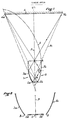
- the device emitting radiation according to the invention is generally designated by the reference 1 in FIG. 1.
- This device can emit any type of electromagnetic radiation, in particular light or infrared. In the following description, the device will however be considered, by way of non-limiting example, as emitting infrared radiation.
- This device comprises a planar source of infrared rays 2, constituting a rectangular radiant panel, which is perpendicular to a plane P which constitutes a plane of symmetry for the whole of the device 1, this plane P being perpendicular to the sheet of the drawing.
- the flat source 2 is defined as extending between two ends 2a and 2b which are symmetrical to each other with respect to the plane P.
- the apparatus emitting infrared radiation also includes a reflector 3 which is intended to return the rays emitted by the source 2 on a target 4 which, for the purpose of simplification, is considered to be plane in FIG. 1 and extending perpendicular to the plane of symmetry P of the transmitting device 1.
- This target 4 extends between two ends 4a, 4b, symmetrical to each other with respect to the plane P, the first end 4a being situated, with respect to the plane P, on the side of the first end 2a of the source 2 while the second end 4b of the target 4 is located on the opposite side, as is the second end 2b of source 2.
- the reflector 3 consists of two cylindrical halves symmetrical with respect to the plane P, namely a left half 3a and a right half 3b.
- Each half-reflector has a cross section which is constituted, in the case of the right half-reflector 3b, by an arc of an ellipse E having for foci the first ends 2a of the planar source 2 and 4a of the target 4 and passing by the second end 2b of the planar source 2.
- the right half-reflector 3b extends between the second end 2b of the planar source 2 and a point A located at the intersection of the ellipse E and the extreme direct radius R1 which extends between the first end 2a of the planar source and the second end 4b of the target 4.
- each ray coming from any point of the planar source 2 is reflected by the reflector 3 in the direction of the target 4 without there being a multiple reflection of any rays nor a prisoner ray between the source 2 and the reflector 3.
- the rays R coming from the first end 2a or left end of the source 2 directly reach the target 4 or are reflected by the right half-reflector 3b, towards the first end 4a of the target 4, without being intercepted by the left half-reflector 3b.
- the two half-reflectors 3a and 3b are not directly connected to the two ends 2a, 2b of the source 2 and they terminate at points B which are located at short distance from the ends 2a, 2b of the source 2. There are thus determined, between the ends 2a, 2b of the source 2 and the points B, openings allowing the entry of air to ensure the internal cooling of the device 1.
- the radiation emitting device according to the invention can be used throughout the visible and invisible spectrum and it can in particular constitute a light beam projector, mounted, for example, on a motor vehicle.
Landscapes
- Physics & Mathematics (AREA)
- General Physics & Mathematics (AREA)
- Optics & Photonics (AREA)
- Toxicology (AREA)
- Engineering & Computer Science (AREA)
- General Engineering & Computer Science (AREA)
- Health & Medical Sciences (AREA)
- Optical Elements Other Than Lenses (AREA)
- Led Device Packages (AREA)
- Radiation-Therapy Devices (AREA)
- Illuminated Signs And Luminous Advertising (AREA)
- Investigating Or Analysing Materials By Optical Means (AREA)
- Measuring And Recording Apparatus For Diagnosis (AREA)
- Transmitters (AREA)
- Inspection Of Paper Currency And Valuable Securities (AREA)
- Discharge Lamps And Accessories Thereof (AREA)
Claims (1)
Priority Applications (1)
| Application Number | Priority Date | Filing Date | Title |
|---|---|---|---|
| AT88402962T ATE72485T1 (de) | 1987-11-25 | 1988-11-24 | Apparatur fuer ausstrahlung von elektromagnetischen wellen, insbesondere fuer den infrarotbereich, mit einer planaren quelle von strahlen und einem reflektor. |
Applications Claiming Priority (2)
| Application Number | Priority Date | Filing Date | Title |
|---|---|---|---|
| FR8716361A FR2623634B1 (fr) | 1987-11-25 | 1987-11-25 | Appareil emetteur de rayonnement infrarouge comportant une source plane de rayons infrarouges et un reflecteur |
| FR8716361 | 1987-11-25 |
Publications (2)
| Publication Number | Publication Date |
|---|---|
| EP0318390A1 EP0318390A1 (de) | 1989-05-31 |
| EP0318390B1 true EP0318390B1 (de) | 1992-02-05 |
Family
ID=9357163
Family Applications (1)
| Application Number | Title | Priority Date | Filing Date |
|---|---|---|---|
| EP88402962A Expired - Lifetime EP0318390B1 (de) | 1987-11-25 | 1988-11-24 | Apparatur für Ausstrahlung von elektromagnetischen Wellen, insbesondere für den Infrarotbereich, mit einer planaren Quelle von Strahlen und einem Reflektor |
Country Status (6)
| Country | Link |
|---|---|
| US (1) | US4922107A (de) |
| EP (1) | EP0318390B1 (de) |
| AT (1) | ATE72485T1 (de) |
| CA (1) | CA1327960C (de) |
| DE (1) | DE3868312D1 (de) |
| FR (1) | FR2623634B1 (de) |
Families Citing this family (16)
| Publication number | Priority date | Publication date | Assignee | Title |
|---|---|---|---|---|
| US5243459A (en) * | 1989-05-05 | 1993-09-07 | The Argonne National Laboratory | Nonimaging radiant energy device |
| FR2648543B1 (fr) * | 1989-06-14 | 1991-09-06 | Armines | Luminaire pour source lumineuse cylindrique |
| US5058982A (en) * | 1989-06-21 | 1991-10-22 | Orbot Systems Ltd. | Illumination system and inspection apparatus including same |
| US5289356A (en) | 1991-07-19 | 1994-02-22 | Nioptics Corporation | Nonimaging optical illumination system |
| US5335152A (en) * | 1991-10-11 | 1994-08-02 | Nioptics Corporation | Nonimaging optical illumination system |
| US5586013A (en) * | 1991-07-19 | 1996-12-17 | Minnesota Mining And Manufacturing Company | Nonimaging optical illumination system |
| FR2683051B1 (fr) * | 1991-10-25 | 1993-12-24 | Armines | Reflecteur pour source de rayonnement a angle de rayonnement lateral maximal controle. |
| US5604607A (en) * | 1992-10-19 | 1997-02-18 | Eastman Kodak Company | Light concentrator system |
| US5517315A (en) * | 1993-10-29 | 1996-05-14 | The United States Of America As Represented By The Secretary Of The Navy | Reflectometer employing an integrating sphere and lens-mirror concentrator |
| US5903403A (en) | 1997-01-24 | 1999-05-11 | Hewlett-Packard Company | Imaging system using a compound elliptical concentrator |
| US6123436A (en) * | 1997-08-05 | 2000-09-26 | Vari-Lite, Inc. | Optical device for modifying the angular and spatial distribution of illuminating energy |
| AU7786998A (en) * | 1998-06-16 | 2000-01-05 | Orbotech Ltd. | Illuminator for inspecting substantially flat surfaces |
| IL131284A (en) | 1999-08-05 | 2003-05-29 | Orbotech Ltd | Illumination for inspecting surfaces of articles |
| JP4200849B2 (ja) * | 2003-07-17 | 2008-12-24 | 日産自動車株式会社 | 車両用赤外線投光器 |
| WO2007129146A1 (en) * | 2006-05-05 | 2007-11-15 | Capan Rahmi Oguz | Hyperbolic solar trough field system |
| AU2017418693B2 (en) * | 2017-06-12 | 2023-07-13 | Solight Ltd. | Radiation collector and method of manufacture thereof |
Family Cites Families (13)
| Publication number | Priority date | Publication date | Assignee | Title |
|---|---|---|---|---|
| US17038A (en) * | 1857-04-14 | Expansive bit | ||
| USRE17038E (en) * | 1928-07-17 | Apparatus | ||
| GB1110073A (en) * | 1965-11-09 | 1968-04-18 | British Iron Steel Research | Improvements in and relating to reflectors |
| US3449561A (en) * | 1967-07-03 | 1969-06-10 | Textron Electronics Inc | Aconic collector |
| US3827059A (en) * | 1972-07-03 | 1974-07-30 | Raytheon Co | Catoptric lens arrangement |
| US4003638A (en) * | 1973-12-28 | 1977-01-18 | The University Of Chicago | Radiant energy collection |
| US3923381A (en) * | 1973-12-28 | 1975-12-02 | Univ Chicago | Radiant energy collection |
| GB1562015A (en) * | 1976-03-03 | 1980-03-05 | Us Energy | Solar concentrator with the angle of incidence of energy on the energy absorber restricted |
| US4114592A (en) * | 1976-08-16 | 1978-09-19 | The United States Of America As Represented By The United States Department Of Energy | Cylindrical radiant energy direction device with refractive medium |
| US4129115A (en) * | 1976-09-27 | 1978-12-12 | Wyatt William G | Radiant energy collector |
| US4066887A (en) * | 1976-10-27 | 1978-01-03 | Maurice Levis | Segmented sectional reflection for the projection of light beams and its method of production |
| JPS5557803A (en) * | 1978-09-21 | 1980-04-30 | Unisearch Ltd | Light concentration unit and light dispersion unit |
| FI841491L (fi) * | 1983-04-25 | 1984-10-26 | Christian Lumpp | Anordning foer aostadkommande och reflektering av infraroed eller ultraviolett straolning. |
-
1987
- 1987-11-25 FR FR8716361A patent/FR2623634B1/fr not_active Expired - Lifetime
-
1988
- 1988-11-22 CA CA000583732A patent/CA1327960C/fr not_active Expired - Fee Related
- 1988-11-22 US US07/275,002 patent/US4922107A/en not_active Expired - Fee Related
- 1988-11-24 DE DE8888402962T patent/DE3868312D1/de not_active Expired - Lifetime
- 1988-11-24 AT AT88402962T patent/ATE72485T1/de active
- 1988-11-24 EP EP88402962A patent/EP0318390B1/de not_active Expired - Lifetime
Also Published As
| Publication number | Publication date |
|---|---|
| CA1327960C (fr) | 1994-03-22 |
| FR2623634B1 (fr) | 1991-08-16 |
| DE3868312D1 (de) | 1992-03-19 |
| FR2623634A1 (fr) | 1989-05-26 |
| ATE72485T1 (de) | 1992-02-15 |
| EP0318390A1 (de) | 1989-05-31 |
| US4922107A (en) | 1990-05-01 |
Similar Documents
| Publication | Publication Date | Title |
|---|---|---|
| EP0318390B1 (de) | Apparatur für Ausstrahlung von elektromagnetischen Wellen, insbesondere für den Infrarotbereich, mit einer planaren Quelle von Strahlen und einem Reflektor | |
| JP5001940B2 (ja) | 光偏向領域を有する光導波体 | |
| US7121679B2 (en) | Illumination apparatus | |
| JP4778503B2 (ja) | ランプ | |
| TWI291568B (en) | LED lighting device and headlamp system | |
| EP0318389B1 (de) | Emissionsvorrichtung für elektromagnetische, insbesondere infrarote Strahlung | |
| US20100046233A1 (en) | LED lighting apparatus | |
| JP2001502113A (ja) | ヘッドライト | |
| FR2570801A1 (fr) | Projecteur de lumiere a plusieurs surfaces reflechissantes | |
| US5475571A (en) | Ring Light collector | |
| US10655809B1 (en) | Vehicle lamp | |
| FR2496841A1 (fr) | Lampe a reflecteur et optique profiles | |
| EP2469650B1 (de) | Funksendevorrichtung | |
| EP1526327B1 (de) | Optische Anordnung und Vorrichtung zur Beleuchtung von Operationsfeldern | |
| JPH0821370B2 (ja) | 自動車等のヘツドライト | |
| JP2000276907A (ja) | 灯 具 | |
| JP2001101913A5 (de) | ||
| FR2525733A1 (fr) | Reflecteur a paraboloides multiples | |
| JP2000149621A (ja) | 車両用前照灯 | |
| WO2010016118A1 (ja) | 照明器具 | |
| FR2768218A1 (fr) | Dispositif d'eclairage et de signalisation a conduit optique de la lumiere, notamment pour vehicules automobiles | |
| JP3244837B2 (ja) | 照明器具 | |
| FR2769993A1 (fr) | Reflecteur concentrant | |
| JPH06302209A (ja) | 列設放射源用インボリュート形反射板 | |
| FR2765951A1 (fr) | Appareil d'eclairage pour lampe fluorescente a cathode froide |
Legal Events
| Date | Code | Title | Description |
|---|---|---|---|
| PUAI | Public reference made under article 153(3) epc to a published international application that has entered the european phase |
Free format text: ORIGINAL CODE: 0009012 |
|
| AK | Designated contracting states |
Kind code of ref document: A1 Designated state(s): AT BE CH DE ES FR GB GR IT LI LU NL SE |
|
| 17P | Request for examination filed |
Effective date: 19890630 |
|
| 17Q | First examination report despatched |
Effective date: 19910426 |
|
| GRAA | (expected) grant |
Free format text: ORIGINAL CODE: 0009210 |
|
| AK | Designated contracting states |
Kind code of ref document: B1 Designated state(s): AT BE CH DE ES FR GB GR IT LI LU NL SE |
|
| PG25 | Lapsed in a contracting state [announced via postgrant information from national office to epo] |
Ref country code: IT Free format text: LAPSE BECAUSE OF FAILURE TO SUBMIT A TRANSLATION OF THE DESCRIPTION OR TO PAY THE FEE WITHIN THE PRE;WARNING: LAPSES OF ITALIAN PATENTS WITH EFFECTIVE DATE BEFORE 2007 MAY HAVE OCCURRED AT ANY TIME BEFORE 2007. THE CORRECT EFFECTIVE DATE MAY BE DIFFERENT FROM THE ONE RECORDED.SCRIBED TIME-LIMIT Effective date: 19920205 Ref country code: SE Effective date: 19920205 Ref country code: AT Effective date: 19920205 Ref country code: GR Free format text: LAPSE BECAUSE OF FAILURE TO SUBMIT A TRANSLATION OF THE DESCRIPTION OR TO PAY THE FEE WITHIN THE PRESCRIBED TIME-LIMIT Effective date: 19920205 Ref country code: ES Free format text: THE PATENT HAS BEEN ANNULLED BY A DECISION OF A NATIONAL AUTHORITY Effective date: 19920205 |
|
| REF | Corresponds to: |
Ref document number: 72485 Country of ref document: AT Date of ref document: 19920215 Kind code of ref document: T |
|
| REF | Corresponds to: |
Ref document number: 3868312 Country of ref document: DE Date of ref document: 19920319 |
|
| GBT | Gb: translation of ep patent filed (gb section 77(6)(a)/1977) | ||
| PGFP | Annual fee paid to national office [announced via postgrant information from national office to epo] |
Ref country code: GB Payment date: 19921116 Year of fee payment: 5 |
|
| PGFP | Annual fee paid to national office [announced via postgrant information from national office to epo] |
Ref country code: LU Payment date: 19921119 Year of fee payment: 5 |
|
| PGFP | Annual fee paid to national office [announced via postgrant information from national office to epo] |
Ref country code: BE Payment date: 19921123 Year of fee payment: 5 |
|
| PGFP | Annual fee paid to national office [announced via postgrant information from national office to epo] |
Ref country code: FR Payment date: 19921125 Year of fee payment: 5 |
|
| PGFP | Annual fee paid to national office [announced via postgrant information from national office to epo] |
Ref country code: CH Payment date: 19921130 Year of fee payment: 5 Ref country code: NL Payment date: 19921130 Year of fee payment: 5 |
|
| PLBE | No opposition filed within time limit |
Free format text: ORIGINAL CODE: 0009261 |
|
| STAA | Information on the status of an ep patent application or granted ep patent |
Free format text: STATUS: NO OPPOSITION FILED WITHIN TIME LIMIT |
|
| 26N | No opposition filed | ||
| PGFP | Annual fee paid to national office [announced via postgrant information from national office to epo] |
Ref country code: DE Payment date: 19930129 Year of fee payment: 5 |
|
| EPTA | Lu: last paid annual fee | ||
| PG25 | Lapsed in a contracting state [announced via postgrant information from national office to epo] |
Ref country code: LU Free format text: LAPSE BECAUSE OF NON-PAYMENT OF DUE FEES Effective date: 19931124 Ref country code: GB Effective date: 19931124 |
|
| PG25 | Lapsed in a contracting state [announced via postgrant information from national office to epo] |
Ref country code: LI Effective date: 19931130 Ref country code: CH Effective date: 19931130 Ref country code: BE Effective date: 19931130 |
|
| BERE | Be: lapsed |
Owner name: ASSOCIATION POUR LA RECHERCHE ET LE DEVELOPPEMENT Effective date: 19931130 |
|
| PG25 | Lapsed in a contracting state [announced via postgrant information from national office to epo] |
Ref country code: NL Effective date: 19940601 |
|
| NLV4 | Nl: lapsed or anulled due to non-payment of the annual fee | ||
| GBPC | Gb: european patent ceased through non-payment of renewal fee |
Effective date: 19931124 |
|
| PG25 | Lapsed in a contracting state [announced via postgrant information from national office to epo] |
Ref country code: FR Effective date: 19940729 |
|
| REG | Reference to a national code |
Ref country code: CH Ref legal event code: PL |
|
| PG25 | Lapsed in a contracting state [announced via postgrant information from national office to epo] |
Ref country code: DE Effective date: 19940802 |
|
| REG | Reference to a national code |
Ref country code: FR Ref legal event code: ST |