EP0318510B1 - Gewebtes tarnmaterial gegen elektromagnetische strahlen - Google Patents
Gewebtes tarnmaterial gegen elektromagnetische strahlen Download PDFInfo
- Publication number
- EP0318510B1 EP0318510B1 EP87905668A EP87905668A EP0318510B1 EP 0318510 B1 EP0318510 B1 EP 0318510B1 EP 87905668 A EP87905668 A EP 87905668A EP 87905668 A EP87905668 A EP 87905668A EP 0318510 B1 EP0318510 B1 EP 0318510B1
- Authority
- EP
- European Patent Office
- Prior art keywords
- layer
- radiation
- front side
- region
- web material
- Prior art date
- Legal status (The legal status is an assumption and is not a legal conclusion. Google has not performed a legal analysis and makes no representation as to the accuracy of the status listed.)
- Expired
Links
- 239000000463 material Substances 0.000 title claims abstract description 46
- 230000005670 electromagnetic radiation Effects 0.000 title claims abstract description 9
- 230000005855 radiation Effects 0.000 claims abstract description 47
- 239000011888 foil Substances 0.000 claims abstract description 35
- 239000004033 plastic Substances 0.000 claims abstract description 13
- 229920003023 plastic Polymers 0.000 claims abstract description 13
- 239000010410 layer Substances 0.000 claims description 53
- 239000002245 particle Substances 0.000 claims description 14
- 239000011248 coating agent Substances 0.000 claims description 11
- 238000000576 coating method Methods 0.000 claims description 11
- PXHVJJICTQNCMI-UHFFFAOYSA-N Nickel Chemical compound [Ni] PXHVJJICTQNCMI-UHFFFAOYSA-N 0.000 claims description 9
- 239000000853 adhesive Substances 0.000 claims description 8
- 239000002184 metal Substances 0.000 claims description 7
- 229910052751 metal Inorganic materials 0.000 claims description 7
- 239000012790 adhesive layer Substances 0.000 claims description 5
- 239000000203 mixture Substances 0.000 claims description 5
- 229910052759 nickel Inorganic materials 0.000 claims description 3
- 229910000480 nickel oxide Inorganic materials 0.000 claims description 3
- GNRSAWUEBMWBQH-UHFFFAOYSA-N oxonickel Chemical compound [Ni]=O GNRSAWUEBMWBQH-UHFFFAOYSA-N 0.000 claims description 3
- 230000001070 adhesive effect Effects 0.000 claims description 2
- 239000003086 colorant Substances 0.000 claims description 2
- 229910044991 metal oxide Inorganic materials 0.000 claims description 2
- 230000001747 exhibiting effect Effects 0.000 claims 1
- 230000002745 absorbent Effects 0.000 abstract description 3
- 239000002250 absorbent Substances 0.000 abstract description 3
- 230000000694 effects Effects 0.000 description 15
- 238000010276 construction Methods 0.000 description 4
- 238000001514 detection method Methods 0.000 description 4
- -1 polytetrafluoroethylene Polymers 0.000 description 3
- 229920001343 polytetrafluoroethylene Polymers 0.000 description 3
- 239000004810 polytetrafluoroethylene Substances 0.000 description 3
- 229920006362 Teflon® Polymers 0.000 description 2
- 238000004519 manufacturing process Methods 0.000 description 2
- 238000000034 method Methods 0.000 description 2
- 239000002344 surface layer Substances 0.000 description 2
- 229910021543 Nickel dioxide Inorganic materials 0.000 description 1
- 239000011247 coating layer Substances 0.000 description 1
- 238000004040 coloring Methods 0.000 description 1
- 238000005260 corrosion Methods 0.000 description 1
- 230000007797 corrosion Effects 0.000 description 1
- 238000010586 diagram Methods 0.000 description 1
- 238000003618 dip coating Methods 0.000 description 1
- 238000002592 echocardiography Methods 0.000 description 1
- 239000004744 fabric Substances 0.000 description 1
- 230000001788 irregular Effects 0.000 description 1
- 239000002648 laminated material Substances 0.000 description 1
- 230000000873 masking effect Effects 0.000 description 1
- MRHPUNCYMXRSMA-UHFFFAOYSA-N nickel(2+) oxygen(2-) Chemical compound [O--].[O--].[Ni++] MRHPUNCYMXRSMA-UHFFFAOYSA-N 0.000 description 1
- 239000000049 pigment Substances 0.000 description 1
- 229920000642 polymer Polymers 0.000 description 1
- 238000002310 reflectometry Methods 0.000 description 1
- 230000000717 retained effect Effects 0.000 description 1
- 210000002105 tongue Anatomy 0.000 description 1
- 230000001131 transforming effect Effects 0.000 description 1
Images

Classifications
-
- H—ELECTRICITY
- H01—ELECTRIC ELEMENTS
- H01Q—ANTENNAS, i.e. RADIO AERIALS
- H01Q17/00—Devices for absorbing waves radiated from an antenna; Combinations of such devices with active antenna elements or systems
- H01Q17/005—Devices for absorbing waves radiated from an antenna; Combinations of such devices with active antenna elements or systems using woven or wound filaments; impregnated nets or clothes
-
- F—MECHANICAL ENGINEERING; LIGHTING; HEATING; WEAPONS; BLASTING
- F41—WEAPONS
- F41H—ARMOUR; ARMOURED TURRETS; ARMOURED OR ARMED VEHICLES; MEANS OF ATTACK OR DEFENCE, e.g. CAMOUFLAGE, IN GENERAL
- F41H3/00—Camouflage, i.e. means or methods for concealment or disguise
-
- Y—GENERAL TAGGING OF NEW TECHNOLOGICAL DEVELOPMENTS; GENERAL TAGGING OF CROSS-SECTIONAL TECHNOLOGIES SPANNING OVER SEVERAL SECTIONS OF THE IPC; TECHNICAL SUBJECTS COVERED BY FORMER USPC CROSS-REFERENCE ART COLLECTIONS [XRACs] AND DIGESTS
- Y10—TECHNICAL SUBJECTS COVERED BY FORMER USPC
- Y10S—TECHNICAL SUBJECTS COVERED BY FORMER USPC CROSS-REFERENCE ART COLLECTIONS [XRACs] AND DIGESTS
- Y10S2/00—Apparel
- Y10S2/90—Camouflaged
-
- Y—GENERAL TAGGING OF NEW TECHNOLOGICAL DEVELOPMENTS; GENERAL TAGGING OF CROSS-SECTIONAL TECHNOLOGIES SPANNING OVER SEVERAL SECTIONS OF THE IPC; TECHNICAL SUBJECTS COVERED BY FORMER USPC CROSS-REFERENCE ART COLLECTIONS [XRACs] AND DIGESTS
- Y10—TECHNICAL SUBJECTS COVERED BY FORMER USPC
- Y10S—TECHNICAL SUBJECTS COVERED BY FORMER USPC CROSS-REFERENCE ART COLLECTIONS [XRACs] AND DIGESTS
- Y10S428/00—Stock material or miscellaneous articles
- Y10S428/919—Camouflaged article
Definitions
- the present invention relates to a web material, a foil for camouflage against electromagnetic radiation. It relates particularly to a material which renders more difficult the possibility of detecting a camouflaged object using different forms of electromagnetic radiation, such as visible light, heat radiation or, for example, laser light from active detectors.
- camouflaged for example vehicles or buildings
- heat radiation of their own which is significantly greater than that of the surroundings, and they can therefore be discovered by means of detectors for infrared light, which can be made very sensitive.
- a threedimensional camouflage material is known through US 4 493 863. This material, however, has no reflecting absorbing surfaces.
- the specification refers to a right to produce tongues extended from the surface of the material by using tension stress in a plastic layer attached to a support.
- US 4 529 633 refers a thermal camouflage laminate material.
- a metal reflection layer is used in order to prevent discovering by means of thermal radiation from equipment and the material with a higher temperature than the surroundings.
- the measures to prevent detection by means of other kinds of radiation is a threedimensional mosaic structure and an outer layer being matte finished, consequently only means for scattering the light or radiation by reflection in all directions.
- the US patent 4 560 595 also teaches in accordance with the preamble of claim 1 a material intended to camouflage thermal radiation by means of a reflecting metal layer. Also here are suggested radiation non-transforming means as mosaic and patch work (claims 7, 8).
- the main means used by this reference is however a double plastic layer onto the outer surface of the metallic layer. In this double layer the two layers are chosen with different thicknesses giving an interference effect.
- the camouflaging web material for camouflaging against electromagnetic radiation comprises several layers and is provided with a front side, which is intended to be turned towards a potential observer or detector, as well as a backside, which is intended to be turned towards an object, which is to be camouflaged, wherein a first layer is formed of a metallic foil with at least one reflective surface toward the front side and with a second surface turned towards the backside and further layers on the first surface of the first layer, characterized by the further layers being the second layer in the form of a surface coating on the side of the first layer turned towards the front side and having a thickness generally less than 1 um and consisting of a mixture of particles of a metallic oxide and a metal with a particle size in the region 10-1.000 ⁇ preferably 100-1.000 ⁇ and by the third layer consisting of a plastic layer having a precisely determined thickness and chosen to provide an adapted absorbtion of radiation in the region 8-13 um and with the side of third layer forming the front side toward the material textured in an embosse
- a material is achieved having good camouflaging characteristics with respect to all previously known methods of detection, the material being made thin and light and can furthermore be produced using efficient industrial methods of mass production.
- Another advantage is that, by means of the invention, a material can be provided which is so thin that it can be produced in the form of a foil which is easy to handle and which can be made self-adhesive for direct securing onto the surface of camouflaged objects.
- Fig. 1 shows a cross section of a preferred embodiment
- fig. 2 shows a view of the material according to the embodiment from its front side
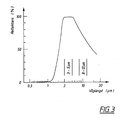
- fig. 3 shows a schematic reflectance curve.
- the best mode of carrying out the invention is a foil having a thickness on the order of tenths of a mm. By making it self-adhesive it can be secured directly onto the surfaces of the objects which are to be camouflaged. This concerns primarily objects with hard, smooth surfaces such as vehicles and other machine equipment, but also certain buildings. It is thus in this preferred product form that the material according to the invention is to be supplied. Within the scope of the invention, however, the material can be supplied in other product forms as well, such as tarpaulins, hoods or other casings for covering objects, or plates which are to be set up or secured.
- the active part of such products is, however, a foil in accordance with the invention but, for these types of products, it can of course be applied in other ways than as a self-adhesive layer.
- the foil contained in the preferred product form, as well as in other product forms, can in turn have alternative detailed constructions, one of which will be described below by way of example. As far as its principle construction is concerned, the foil is, however, the same in all forms, and this principle construction will be described below.
- the foil according to the invention which is designated by 1, exhibits a front side 2, which is intended to be turned outwards towards the potential observer or detector, and a backside 3 which is to be turned towards the object which is to be camouflaged.
- the foil is built up from a number of layers. Near the backside 3 there is a thin metallic foil 4 with a reflective surface. It is important that the foil should be reflective on the surface which is turned towards the front side 2. It is advantageous that even its inner surface be reflective, but it can however, alternatively be provided with an underlying layer, even colored throughout, as a carrier for increasing the mechanical strength without affecting significantly the camouflaging properties mentioned below.
- a surface coating 5 which has the property of being absorbent for visible light and near-infrared radiation (wave lengths up to approximately 2 ⁇ m) but transparent for thermalinfrared radiation) the wave length region 3-100 ⁇ m).
- the surface coating 5 supports a plastic layer 6 having a precisely determined thickness, the outwardly turned surface of which forms said front surface 2.
- the front surface of the foil is textured by means of an embossment 7.
- This embossment may consist of a large number of tightly packed groves, which form an irregular pattern. An example of such a pattern is shown in a view of the material in fig. 2.
- the preferred embodiment of the foil exhibits an adhesive layer 8 on its backside 3.
- This is of a self-adhesive type so that the foil may be secured on surfaces of an object, preferably the object which is to be camouflaged, or onto a fabric, a plate or some other supporting material.
- the effect is related to specific wave length regions expressed in micrometers for light radiation and thermal radiation and in mm for radio waves.
- the specified reflection relates to reflection from the front surface 2 of radiation directed against it in the form of visible light, laser light and radar waves.
- the reflection in the region for thermal infrared (IR) radiation is given as comparitive values.
- Camouflage against IR-radiation which is directed against the front surface is, however, not of primary interest but rather, the camouflage against radiation in the thermal region relates to camouflaging the radiation of the camouflaged object itself because of it having a different temperature than the surroundings, which is often the case with vehicles, other machine equipment, and buildings. Therefore, for the thermal wave length region even emission, that is, radiation from the front surface 2 because of the temperature of the foil, which can be influenced for example by incident radiation against the backside 3 or by conduction, is given. It is to be noted that reflection and emission for a surface are inversely proportional to one another.
- a certain irregularity by means of texturing and color variations makes it difficult to discern when it is located in an environment which has surfaces which are similarly irregularly textured and colored such as often occur in terrain.
- These important effects for lessening the risk of discovery by observation are achieved by means of a suitable texturing of the plastic layer 6 in the manner shown in fig. 2.
- the entire material 1, in the form of foil can be embossed so that the texturing is produced. If the material is to be fastened on a smooth surface the adhesive layer 8 can then even out the unevenness of the backside of the foil so that fully satisfactory contact is achieved.
- the embossment is exaggerated, as well as the thickness of the material.
- the material is preferably only a few tenths of a mm thick so that the embossment is only a few hundredths or tenths of a mm high.
- the said color variations can be achieved by varying the thickness of thesurface coating layer 5 of the metallic foil. Interference phenomena thereby give rise to different colors, preferably in the green and blue regions. In this way one avoids coloring using pigment, as has previously been common, which can disturb the desired influence on radiation in regions other than visible light.
- the metallic foil itself has, however, certain negative effects when it comes to other radiation. Since it is reflective, without special measures it would lead to a great risk of discovery when struck by radiation in the form of visible light or from active detectors. Masking the metallic foil using an opaque coating would, on the other hand, lessen or eliminate the effect on the IR-radiation from the camouflaged object. By means of the surface coating 5, however, the effect is achieved that the said incident radiation is damped with respect to reflection by the surface of the metallic foil whereas reflection of IR-radiation is retained and, hence, the low, adapted thermal emission as well.
- the coating by means of radiation selective influence, in particular, by means of a particle construction of the layer which provides a particle distance in the region for the wave length of visible light. It is absorbed to a great extent between the particles whereas the IR-radiation, with its longer wave length, passes the particle bed.
- the layer can be built up of non-transparent particles and transparent particles, which form the transparent portions, where the visible light is absorbed.
- the surface coating can consist of a mixture of metallic nickel and nickel oxide, which is transparent. The thickness in this case is less than 1 ⁇ m. The color is dark blue to black.
- This radiation selective effect can however also be achieved using different compositions than the one mentioned, preferably particles of a metal and its oxide.
- the metal foil thus adjusts the emission in the thermal region from the camouflaged object. It is however the case that the emission in the central thermal region, approximately 8-13 ⁇ m, is not affected to such a degree as would be desired. According to the invention this region is therefore influenced by a special means, namely, the plastic layer 6. It has namely been shown that certain types of plastics, especially polytetrafluoroethylene, Teflon® is absorbent with respect to this thermal region.
- Influence of the radiation within the said region will, just as influence within the other thermal region, be adjusted so that the IR-radiation corresponds to the IR-radiation of the surroundings.
- This adjustment is carried out by means of an adapted thickness for the plastic layer.
- a thickness of 10-20 ⁇ m is suitable.
- the following characteristics should be aimed for: Good resistance to corrosion, which is attained primarily by the choice of a suitable metal in the foil 4 combined with a choice of plastic in the layer 6; as well as good thermal contact with the base, which is achieved primarily by good adhesion of the product which is preferably made as a self-adhesive foil.
- the texturing 7 of the surface layer must in this case not affect the backside 3 in such a way that the adhesive bond is jeopardized.
- the metallic foil 4 is based primarily on nickel.
- the surface coating 5 consists of a mixture of particles of nickel oxide and metallic nickel. The thickness is less 1 ⁇ m. The color is dark blue to black.
- the surface layer 6 consists of a polymer layer. Polytetrafluoroethylene (Teflon®) has been shown to provide desirable characteristics.
- Teflon® Polytetrafluoroethylene
- the layer can be applied to the underlying surface coating 5 by means of dip-coating.
- the texturing 7 on the front surface 2 has been defined earlier.
- the adhesive layer 8 can be of a previously known type which is used for self-adhesive metallic foils for use with solar collectors.
Landscapes
- Engineering & Computer Science (AREA)
- General Engineering & Computer Science (AREA)
- Laminated Bodies (AREA)
- Aiming, Guidance, Guns With A Light Source, Armor, Camouflage, And Targets (AREA)
- Materials For Medical Uses (AREA)
- Chemical Or Physical Treatment Of Fibers (AREA)
Claims (5)
Priority Applications (1)
| Application Number | Priority Date | Filing Date | Title |
|---|---|---|---|
| AT87905668T ATE68874T1 (de) | 1986-08-21 | 1987-08-21 | Gewebtes tarnmaterial gegen elektromagnetische strahlen. |
Applications Claiming Priority (2)
| Application Number | Priority Date | Filing Date | Title |
|---|---|---|---|
| SE8603522 | 1986-08-21 | ||
| SE8603522A SE8603522D0 (sv) | 1986-08-21 | 1986-08-21 | Banformigt material for kamouflage mot elektromagnetisk stralning |
Publications (2)
| Publication Number | Publication Date |
|---|---|
| EP0318510A1 EP0318510A1 (de) | 1989-06-07 |
| EP0318510B1 true EP0318510B1 (de) | 1991-10-23 |
Family
ID=20365359
Family Applications (1)
| Application Number | Title | Priority Date | Filing Date |
|---|---|---|---|
| EP87905668A Expired EP0318510B1 (de) | 1986-08-21 | 1987-08-21 | Gewebtes tarnmaterial gegen elektromagnetische strahlen |
Country Status (8)
| Country | Link |
|---|---|
| US (1) | US4953922A (de) |
| EP (1) | EP0318510B1 (de) |
| JP (1) | JPH02500731A (de) |
| AT (1) | ATE68874T1 (de) |
| AU (1) | AU604053B2 (de) |
| DE (1) | DE3774129D1 (de) |
| SE (1) | SE8603522D0 (de) |
| WO (1) | WO1988001363A1 (de) |
Families Citing this family (33)
| Publication number | Priority date | Publication date | Assignee | Title |
|---|---|---|---|---|
| SE8704197D0 (sv) * | 1987-10-28 | 1987-10-28 | Diab Barracuda Ab | Material |
| JP2506447B2 (ja) * | 1989-06-02 | 1996-06-12 | 株式会社クラレ | 対遠赤外線偽装用フイルム |
| JP2558349B2 (ja) * | 1989-06-02 | 1996-11-27 | 株式会社クラレ | 複合偽装用シート |
| GB2237862B (en) * | 1989-10-30 | 1994-07-06 | Colebrand Ltd | Absorbers |
| GB2274154B (en) * | 1989-12-04 | 1995-01-04 | Marconi Gec Ltd | Modifying the infra-red appearance of a body |
| WO1991016592A1 (en) * | 1990-04-23 | 1991-10-31 | Courtaulds Advanced Materials (Holdings) Limited | Visual and thermal camouflage materials and manufacturing method |
| FR2733311B1 (fr) * | 1992-12-15 | 1998-01-02 | Thomson Brandt Armements | Dispositif de camouflage auto-adaptatif |
| JP2996078B2 (ja) * | 1992-12-22 | 1999-12-27 | 三菱電機株式会社 | 赤外線ステルス装置 |
| DE19710692C2 (de) * | 1997-03-14 | 1999-09-09 | Dornier Gmbh | Multispektrales Tarnelement |
| US6194329B1 (en) | 1998-01-21 | 2001-02-27 | Brookwood Companies, Incorporated | Reversible fabric for use in military environments and method of making same |
| CA2340452A1 (en) * | 1998-08-15 | 2000-03-16 | Delta Thermal Systems, Inc. | Method of reducing infrared viewability of objects |
| WO2000031493A1 (es) * | 1998-11-26 | 2000-06-02 | Gonzalez Baena Carlos Jesus | Tejido mimetico interactivo |
| ES2151431B1 (es) * | 1998-11-26 | 2001-08-16 | Gonzalez Baena Carlos Jesus | Tejido mimetico interactivo. |
| US6507101B1 (en) * | 1999-03-26 | 2003-01-14 | Hewlett-Packard Company | Lossy RF shield for integrated circuits |
| AU775033B2 (en) * | 1999-10-01 | 2004-07-15 | John L. Larue | Camouflaged structure and method of camouflaging a structure against a background having a generally uniform composition |
| US6689476B2 (en) * | 2001-06-27 | 2004-02-10 | Guardian Industries Corp. | Hydrophobic coating including oxide of Ni and/or Cr |
| GB0209242D0 (en) * | 2002-04-23 | 2002-06-05 | Omova Wallcovering Uk Ltd | Camouflage covering |
| FR2857458A1 (fr) * | 2003-07-09 | 2005-01-14 | Centre Nat Rech Scient | Antenne thermique. |
| FR2906021B1 (fr) | 2006-09-14 | 2008-11-21 | Mbda France Sa | Couverture de camouflage multispectral. |
| DE102006059955B4 (de) * | 2006-12-19 | 2008-12-04 | Diehl Bgt Defence Gmbh & Co. Kg | Strahlungsfilter |
| US8916265B1 (en) | 2007-11-09 | 2014-12-23 | W. L. Gore & Associates, Inc. | Multi-spectral, selectively reflective construct |
| US9276324B2 (en) * | 2007-11-09 | 2016-03-01 | W. L. Gore & Associates, Inc. | Multi-spectral, selectively reflective construct |
| US8220379B2 (en) * | 2010-01-27 | 2012-07-17 | Curry Reed F | Camouflage in the near ultraviolet spectrum |
| USD676674S1 (en) * | 2011-08-25 | 2013-02-26 | Lg Hausys, Ltd. | Sheet for vehicle seats |
| USD676667S1 (en) * | 2011-08-25 | 2013-02-26 | Lg Hausys, Ltd. | Sheet for vehicle seats |
| US9587913B2 (en) | 2013-01-18 | 2017-03-07 | W. L. Gore & Associates, Inc. | Incised composite material for selective, multispectral reflection |
| DE102014103601A1 (de) * | 2014-03-17 | 2015-09-17 | Thyssenkrupp Ag | Vorrichtung zur Reduktion der effektiven Radarrückstrahlfläche |
| KR101702188B1 (ko) * | 2014-12-22 | 2017-02-03 | 현대로템 주식회사 | 레이저 신호 방해 기능을 갖는 전투차량용 패널모듈 |
| DE102015202551A1 (de) * | 2015-02-12 | 2016-08-18 | Thyssenkrupp Ag | Faltbarer RCS Behälter |
| CN110763084B (zh) * | 2019-10-25 | 2022-05-27 | 中国人民解放军国防科技大学 | 可见光和热红外兼容的自适应伪装装置及显示模块 |
| SE544415C2 (en) | 2020-10-15 | 2022-05-17 | Saab Ab | A camouflage tape, and camouflage tape system for temporary multispectral camouflage of objects |
| IL291529B2 (en) | 2022-03-20 | 2023-07-01 | Ametrine Tech Ltd | External camouflage system |
| IL300318B2 (en) * | 2023-01-31 | 2024-07-01 | Ametrine Tech Ltd | Modular camouflage system and its use |
Family Cites Families (9)
| Publication number | Priority date | Publication date | Assignee | Title |
|---|---|---|---|---|
| DE1191064B (de) * | 1953-07-02 | 1965-04-15 | Eltro G M B H & Co Ges Fuer St | Infrarot-Pigment-Gemische fuer Tarnungszwecke |
| DE2750919C1 (de) * | 1977-11-15 | 1984-03-01 | Pusch, Günter, Dr.-Ing., 6903 Neckargemünd | Breitbandige Tarnung militaerischer Ziele |
| US4308882A (en) * | 1979-05-31 | 1982-01-05 | Pusch Guenter | Tents for military use and providing protection against modern sight and IR-optical search methods |
| SE434996B (sv) * | 1983-01-14 | 1984-08-27 | Diab Barracuda Ab | Halat kamouflagematerial |
| US4529633A (en) * | 1983-01-14 | 1985-07-16 | Diab-Barracuda Ab | Thermal camouflage |
| SE457115B (sv) * | 1983-03-25 | 1988-11-28 | Diab Barracuda Ab | Termisk och optisk kamouflage |
| US4479994A (en) * | 1983-05-18 | 1984-10-30 | The United States Of America As Represented By The Secretary Of The Army | Wide band energy absorbing camouflage blanket |
| US4640851A (en) * | 1985-04-01 | 1987-02-03 | Gunter Pusch | Broad band camouflage screen having a frequency dependent radar attenuation |
| US4659602A (en) * | 1985-11-12 | 1987-04-21 | Jorgen Birch | Broad spectrum camouflage mat |
-
1986
- 1986-08-21 SE SE8603522A patent/SE8603522D0/xx unknown
-
1987
- 1987-08-21 WO PCT/SE1987/000367 patent/WO1988001363A1/en not_active Ceased
- 1987-08-21 AU AU78729/87A patent/AU604053B2/en not_active Ceased
- 1987-08-21 AT AT87905668T patent/ATE68874T1/de active
- 1987-08-21 JP JP62505201A patent/JPH02500731A/ja active Pending
- 1987-08-21 DE DE8787905668T patent/DE3774129D1/de not_active Expired - Fee Related
- 1987-08-21 EP EP87905668A patent/EP0318510B1/de not_active Expired
- 1987-08-21 US US07/314,764 patent/US4953922A/en not_active Expired - Fee Related
Also Published As
| Publication number | Publication date |
|---|---|
| ATE68874T1 (de) | 1991-11-15 |
| JPH02500731A (ja) | 1990-03-15 |
| EP0318510A1 (de) | 1989-06-07 |
| WO1988001363A1 (en) | 1988-02-25 |
| DE3774129D1 (de) | 1991-11-28 |
| AU604053B2 (en) | 1990-12-06 |
| SE8603522D0 (sv) | 1986-08-21 |
| AU7872987A (en) | 1988-03-08 |
| US4953922A (en) | 1990-09-04 |
Similar Documents
| Publication | Publication Date | Title |
|---|---|---|
| US4953922A (en) | Web material for camouflage against electromagnetic radiation | |
| EP0123660B1 (de) | Thermische und optische Tarnung | |
| JP4944852B2 (ja) | 遮熱透湿防水シート | |
| KR101926909B1 (ko) | 선택적, 다중 스펙트럼 반사를 위한 절개된 복합 재료 | |
| CA2158917A1 (en) | Colour deformable mirror device having optical thin film interference colour coatings | |
| US4640851A (en) | Broad band camouflage screen having a frequency dependent radar attenuation | |
| CN1099872A (zh) | 立方隅角返回反射物品 | |
| US5077556A (en) | Canopy for screening objects | |
| JP2001508166A (ja) | 半透明な多孔質絶縁材料を有するファサードシステム | |
| US4743478A (en) | Broad band camouflage screen having a frequency dependent radar attenuation | |
| JPH0328697A (ja) | 偽装材 | |
| CA1140442A (en) | Heat reflecting wall-cover | |
| KR20220155602A (ko) | 반사율이 개선된 페인트 | |
| EP0114154B1 (de) | Wärmetarnung | |
| US4457966A (en) | Cover-substrate support material | |
| KR20220157497A (ko) | 재귀반사성 안료 및 페인트 | |
| AU729442B2 (en) | Camouflage structure | |
| US20050118402A1 (en) | Camouflage covering | |
| GB1605261A (en) | Camouflage system | |
| WO1991016592A1 (en) | Visual and thermal camouflage materials and manufacturing method | |
| CN104536072A (zh) | 一种微棱镜反光阻燃带及其制造方法 | |
| CN115558351A (zh) | 一种提高辐射制冷涂层辐射制冷性能的方法 | |
| CN121424860A (zh) | 防伪元件和防伪产品 | |
| JPH065951U (ja) | 乳半色板 | |
| JPH095516A (ja) | 熱線遮蔽シート |
Legal Events
| Date | Code | Title | Description |
|---|---|---|---|
| PUAI | Public reference made under article 153(3) epc to a published international application that has entered the european phase |
Free format text: ORIGINAL CODE: 0009012 |
|
| 17P | Request for examination filed |
Effective date: 19890207 |
|
| AK | Designated contracting states |
Kind code of ref document: A1 Designated state(s): AT BE CH DE FR GB IT LI LU NL SE |
|
| 17Q | First examination report despatched |
Effective date: 19900706 |
|
| GRAA | (expected) grant |
Free format text: ORIGINAL CODE: 0009210 |
|
| AK | Designated contracting states |
Kind code of ref document: B1 Designated state(s): AT BE CH DE FR GB IT LI LU NL SE |
|
| PG25 | Lapsed in a contracting state [announced via postgrant information from national office to epo] |
Ref country code: IT Free format text: LAPSE BECAUSE OF FAILURE TO SUBMIT A TRANSLATION OF THE DESCRIPTION OR TO PAY THE FEE WITHIN THE PRESCRIBED TIME-LIMIT;WARNING: LAPSES OF ITALIAN PATENTS WITH EFFECTIVE DATE BEFORE 2007 MAY HAVE OCCURRED AT ANY TIME BEFORE 2007. THE CORRECT EFFECTIVE DATE MAY BE DIFFERENT FROM THE ONE RECORDED. Effective date: 19911023 Ref country code: LI Effective date: 19911023 Ref country code: AT Effective date: 19911023 Ref country code: BE Effective date: 19911023 Ref country code: NL Effective date: 19911023 Ref country code: SE Effective date: 19911023 Ref country code: CH Effective date: 19911023 Ref country code: FR Effective date: 19911023 |
|
| REF | Corresponds to: |
Ref document number: 68874 Country of ref document: AT Date of ref document: 19911115 Kind code of ref document: T |
|
| REF | Corresponds to: |
Ref document number: 3774129 Country of ref document: DE Date of ref document: 19911128 |
|
| REG | Reference to a national code |
Ref country code: CH Ref legal event code: PL |
|
| EN | Fr: translation not filed | ||
| NLV1 | Nl: lapsed or annulled due to failure to fulfill the requirements of art. 29p and 29m of the patents act | ||
| PG25 | Lapsed in a contracting state [announced via postgrant information from national office to epo] |
Ref country code: GB Effective date: 19920821 |
|
| PLBE | No opposition filed within time limit |
Free format text: ORIGINAL CODE: 0009261 |
|
| STAA | Information on the status of an ep patent application or granted ep patent |
Free format text: STATUS: NO OPPOSITION FILED WITHIN TIME LIMIT |
|
| PG25 | Lapsed in a contracting state [announced via postgrant information from national office to epo] |
Ref country code: LU Free format text: LAPSE BECAUSE OF NON-PAYMENT OF DUE FEES Effective date: 19920831 |
|
| 26N | No opposition filed | ||
| GBPC | Gb: european patent ceased through non-payment of renewal fee |
Effective date: 19920821 |
|
| PG25 | Lapsed in a contracting state [announced via postgrant information from national office to epo] |
Ref country code: DE Effective date: 19930501 |