EP0318577B1 - Flussregelungsanordnung zur intravenösen verabreichung von flüssigkeiten - Google Patents
Flussregelungsanordnung zur intravenösen verabreichung von flüssigkeiten Download PDFInfo
- Publication number
- EP0318577B1 EP0318577B1 EP88906327A EP88906327A EP0318577B1 EP 0318577 B1 EP0318577 B1 EP 0318577B1 EP 88906327 A EP88906327 A EP 88906327A EP 88906327 A EP88906327 A EP 88906327A EP 0318577 B1 EP0318577 B1 EP 0318577B1
- Authority
- EP
- European Patent Office
- Prior art keywords
- valve
- metering
- flow
- valve according
- valving member
- Prior art date
- Legal status (The legal status is an assumption and is not a legal conclusion. Google has not performed a legal analysis and makes no representation as to the accuracy of the status listed.)
- Expired - Lifetime
Links
Images


Classifications
-
- F—MECHANICAL ENGINEERING; LIGHTING; HEATING; WEAPONS; BLASTING
- F16—ENGINEERING ELEMENTS AND UNITS; GENERAL MEASURES FOR PRODUCING AND MAINTAINING EFFECTIVE FUNCTIONING OF MACHINES OR INSTALLATIONS; THERMAL INSULATION IN GENERAL
- F16K—VALVES; TAPS; COCKS; ACTUATING-FLOATS; DEVICES FOR VENTING OR AERATING
- F16K3/00—Gate valves or sliding valves, i.e. cut-off apparatus with closing members having a sliding movement along the seat for opening and closing
- F16K3/30—Details
- F16K3/32—Means for additional adjustment of the rate of flow
-
- A—HUMAN NECESSITIES
- A61—MEDICAL OR VETERINARY SCIENCE; HYGIENE
- A61M—DEVICES FOR INTRODUCING MEDIA INTO, OR ONTO, THE BODY; DEVICES FOR TRANSDUCING BODY MEDIA OR FOR TAKING MEDIA FROM THE BODY; DEVICES FOR PRODUCING OR ENDING SLEEP OR STUPOR
- A61M5/00—Devices for bringing media into the body in a subcutaneous, intra-vascular or intramuscular way; Accessories therefor, e.g. filling or cleaning devices, arm-rests
- A61M5/14—Infusion devices, e.g. infusing by gravity; Blood infusion; Accessories therefor
- A61M5/168—Means for controlling media flow to the body or for metering media to the body, e.g. drip meters, counters ; Monitoring media flow to the body
- A61M5/16877—Adjusting flow; Devices for setting a flow rate
Definitions
- the present invention relates to a device for regulating and controlling the flow of intravenous (IV) and parenteral fluids. More particularly, the present invention relates to a flow metering device for precisely establishing and maintaining a preselected flow rate during the administration of IV liquids to the patient.
- IV intravenous
- parenteral fluids More particularly, the present invention relates to a flow metering device for precisely establishing and maintaining a preselected flow rate during the administration of IV liquids to the patient.
- IV infusion The gravity administration of fluids by IV infusion is a common medical procedure.
- Representative intravenous fluids include blood, plasma, dextrose and isotonic saline solutions.
- IV infusions are generally carried out with the container of IV fluid suspended above the patient.
- Customarily such containers have a seal which is broken by the insertion of a spike and the fluid is delivered to the patient at an administration needle through a drip chamber and flexible tubing connected to the spike.
- the purpose of the drip chamber is to facilitate the determination of the flow or drip rate through the tubing.
- the infusion rate is generally regulated by use of an external pinch valve or roller clamp associated with the tubing for the more common gravity type infusions.
- the tubing and needle are purged of air by initiating a flow of fluid through the tubing.
- the needle is then inserted into a venapuncture site at a suitable location such as in the forearm or wrist of the patient and infusion of fluid is initiated.
- a venapuncture site occurs in the lower arm of the patient, the arm should be properly stabilized on a contoured IV arm support.
- Medical personnel administering the IV will adjust the pinch valve or roller to restrict the IV tubing and the number of drops passing through the drip chamber are counted. The appropriate flow rate is established by trial and error, by progressively restricting or opening the tubing at the pinch valve.
- the administration procedure described above requires the attention of medical personnel for a substantial time in the initial establishment of the proper flow rate and in continual monitoring. It is general pratice of medical personnel to periodically check the flow rate by counting the drops of fluid that pass through the drip chamber. Conventional procedures as described not only require substantial time but are often inaccurate. Temperature changes cause expansion and contraction of the IV tubing allowing the flow rate to vary. The tubing may loose "memory" and collapse under continuous squeezing necessitating constant readjustment of the setting. Roller clamps or pinch valves of the general type described have a tendency to slip off the tubing which can pose a threat to the patient.
- U.S. Patent No. 3,785,378 to Stewart shows a valve for the administration of intravenous fluids which has an annular member forming a central passage through which fluid is flowable to an end face having multiple grooves. The inner ends of the multiple grooves communicate with the passage and a flow control member is rotatable to place the flow port successively and selectively in communication with the grooves to vary the flow rate.
- a flow passage is provided within a housing and is connectable to a source of IV fluid and to a delivery tube terminating at an administration needle.
- a metering pin is axially movable within the flow passage relative to a valve seat and defining a flow passageway and variable area flow notch which are positionable relative to the valve seat to regulate flow from a full flow purge position to a flow blocking position.
- the positioning of the metering pin is accomplished by a cam engaging a portion of the metering pin which forms a cam follower.
- the cam is manually adjustable by a dial on the device to accomplish accurate, repeatable and continuous flow adjustment over a full range.
- the system incorporates the metering apparatus, source of IV fluid, drip chamber and administration means. The apparatus and system works particularly well providing a high degree of accuracy and is competitive even with electronic flow controllers.
- a flow regulator which is used for precise adjustement of gravity infusions or transfusions whereby a casing with an inlet port and outlet port contains a cylindrical valve body, the cover of which has a groove of variable cross-section for regulating the flow between the inlet and outlet ports.
- the groove extends in a plane comprising the outlet port of the casing, perpendicular to the axis of the body at an angle of about 320°.
- a channel in the form of a groove starting from the largest cross-section of the groove extends parallel to the axis of the body and is linked with a circular groove extending around the periphery of the valve body into which the inlet port leads.
- the groove is linked with the inlet port via the channel and circular groove and viewed from drownstream and according to the angular position of the body a cross-section of varying size of the groove is linked with the outlet port. This enables a varying number of drops per unit of time to be fed from the casing.
- Prior WO 86/00682 patent discloses a metering apparatus and system for controlling the administration of IV fluids having a valve housing with a valving chamber therein.
- a rotatable valve body member is positioned within the valve chamber and a valve passageway of variable cross-sectional area is provided at either the chamber or on the valve member.
- the effective area and lenght of the valve passageway interposed between the inlet and outlet to the valve is adjustable to regulate the flow range of rotation only over approximately 180° by moving the valve body relative to the valve member.
- substantially the entire 360° surface of the valving member is used to regulate flow. This permits flow ranges to be spread over a greater circumferential length making the operation of the unit easier and more precise since a small movement will not have as great an effect on the flow rate. Also, because the flow regulation is extended over a full 360°, the appropriate indicia carried on the dial member may be made larger, making them easier to read and providing a greater number of graduations indicating various flow positions.
- the present invention concerns an IV metering valve for use in an IV system having a source of fluid connnected to an administration needle via a flexible tubing line, comprising :
- said bridge 16 has a cross-sectional area larger than the cross-sectional area of either said metering groove 12 or flow channel 17.
- the present invention achieves the above objects and advantages and provides a unique IV control device which can be adjusted to maintain various settings from zero to full flow with accuracy and repeatability.
- the flow control device of the present invention comprises a housing which has an inlet and outlet and a metering member of a first plastic material.
- a flow metering member and associated valing member having a variable area flow path is rotatable witin the housing by means of a manually adjustable dial member.
- the flow metering member selectively places the inlet and outlet in communication via the flow path to regulate the flow from a purge position through a flow adjusting range and to a stop flow position.
- the inlet and outlet are connectable in the IV tubing line which attaches the source of IV fluid to the administration needle.
- the valving member is fabricated of a second plastic material which is selected to effect sealing and minimize heat shrinkage.
- a backplate may be selectively attachable to the valve member to provide additional gripping surface for the medical attendant.
- a security cover may also be associated with the valving member to secure the valving member from tampering or inadvertant adjustment by unauthorized persons.
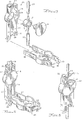
- the valve of the present invention is generally having a generally cylindrical valve housing 1 defining a valve chamber which is closed at one end and open at the other end.
- the inlet 2 and outlet 3 communicate with the valve chamber and are positioned approximately 180° apart with the outlet 3 being axially offset from the inlet 2.
- metering member 4 has an axle 5 and an integrally formed dial member 6 which is preferably knurled about its outer periphery to facilitate manual rotation by the user.
- Cylindrical valving member 7 rotates with axle 5 and is snugly engaged in the valve chamber.
- the valve housing 1 is preferably a rigid, hard plastic material such as ABS, XT of the like as is the metering member 4 and integral axle 5 and dial member 6.
- the valving member 7 is preferably of a semi-rigid plastic material such as PVC, LDP, C-Flex®, Santoprene® or other similar material.
- the valving member 7 may be suitably grooved at recess 8.
- the axle 5 may be provided with a cooperating projections 9 to be received in recesses 8 for properly aligning these components when they are assembled and to prevent relative rotation.
- the dial member 6 may include an annular flanged skirt 10 with an inwardly turned lip engageable with a peripheral flange 11 on the valve housing 1 to secure the valve housing 1 in position and prevent separation of the assembled components while permitting rotation of the valving 7 and metering 4 members relative to the valve housing 1.
- the valve also includes an O-ring 52.
- the configuration of the valving member 7 permits the valving member to turn substantially 360° to increase accuracy and to facilitate ease of adjustment although the in-and outlet 2, 3 are spaced only 180° apart.
- the outer surface of the valving member 7 is provided with a first circumferential metering groove 12 which begins adjacent land area 13.
- Metering groove 12 extends circumferentially about the valving member 7 and progressively increases in cross-sectional area from the distal end 14 to area 15 of the metering groove 12 where the metering groove 12 intersects axial bridge section 16.
- Metering groove 12 may be of various cross-sectional shapes as for example V-shaped, U-shaped of the like and is of varying cross section decreasing progressively from section 15 to section 14.
- the metering groove 12 communicates axially with flow channel 17 across bridge section 16.
- Flow channel 17 extends circumferentially from bridge section 16 along outer surface of the valving member 7 generally parallel to the metering groove 12 and terminates at end wall 18 adjacent land area 13. It will be seen that the inlet 2 is axially aligned with the metering groove 12 and the outlet 3 is axially displaced from the inlet 2 to align with the flow channel 17.
- valve At the point the inlet 2 is in communication with the area 15 of the metering groove where the metering groove intersects bridge section 16, the valve is in the full flow position or purge position as seen in Figure 7. A direct flow path from inlet 2 to outlet 3 is established via flow channel 17. In this position, the system may be purged of air prior to IV administration or a rapid infusion may be administered through the system.
- the exterior of the dial member 7 surface may be provided with appropriate indicia indicating various increments of flow rate from closed position to full flow and purge position. Since the metering occures over a full 360° of the dial member 7 surface, more precise setting of the valve is permitted. Further, additional graduations may be provided on the dial surface for the convenience of the user.
- the flow channel 7 serves as a fluid passage for all flow positions of the valve from initiation of metering through the full range of metering to purge.
- the valve provides accuracy, repeatability with minimum of moving parts.
- the components may be conveniently fabricated by plastic molding techniques and the use of plastic materials of dissimilar hardness provides a sealing at the inner face of the valving member 7 and valve chamber.
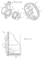
- FIG. 8 through 12 Another embodiment of the present invention is illustrated in Figures 8 through 12.
- the valve member and flow passageways are configured as described with reference to Figures 1 to 7 so that the valving member 7 regulates flow over substantially a 360° range of rotation.
- the vastaly advantage of the embodiment shown in Figures 8 to 12 is the achievement of a precise, ultra low infusion rate that is highly desirable in intravenous therapy.
- a low flow rate is often necessary, particularly to maintain a KVO (keep vein open) setting. It is not uncommon for patients with long hopitalization periods or other certain physical conditions to develop veins which are collapsed or atrophied. Therefore, medical practice is to maintain the patient connected to an ultra low rate intravenous feeding.
- the intravenous feeding maintains the patient's vein in an open condition and provides medical personnel a pathway for quick access for administration of medications or drugs.
- KVO settings are typically in the range of 5 cc. per hour.
- Such low infusion rates have not been possible with low-cost gravity devices as found in the prior art. Until now, these precise ultra-low rates were only possible with any degree of reliability with computerized volumetric pumps which are expensive and are not available at all medical facilities.
- Conventional devices such as roller clamps and prior infusion control devices are not capable of achieving with accuracy and repeatability low rates in the range of 5 cc. per hour.
- valve of the present invention is generally constructed as has been described with reference to Figures 1 to 7.
- node 19 In the "off" position, node 19 is in exact registry with inlet 2 and similarly node 20 is in direct registry with outlet 3. Slight rotation of the dial will move node 19 to the position shown in Figures 11 and 12 which allows a minute volume of fluid to flow from the inlet 2 to flow channel 17. As rotation of the valve continues, nodes 19 and 20 move further out of registry with their associated in- and outlet 2, 3.
- the nodes 19 and 20 are in the form of small generally convex protrusions on the surface of the valving member 7.
- the protrusions as will be explained hereafter, are formed in situ in a remolding process in the land area of the valving member.
- the nodes 19, 20 have a peripheral imprint exactly conforming to and, in fact, determined by the precise outlines of the inlet 2 and the outlet 3. In the "off" position, the nodes provide a tight fluid seal.
- the nodes are moved slightly out of registry with the associates in- and outlet, as seen in Figs. 11 and 12, limited flow is permitted maintaining an ultra-low KVA rate. Further rotation of the valve will result in the inlet 2 being aligned with the metering groove 12 or bridge 16 and purge and normal flow regulation as described with reference to Figs. 1 to 7 are achieved.
- the formation of the nodes in situ is accomplished by applying heat to the assembled valve.
- the valving member 7 and housing 1 are engaged in an interference fit in the range of 25 ⁇ m to 50 ⁇ m.
- the assembled condition prior to heating is shown in Fig. 9 in which the valving member 7 is tightly positioned in the valve chamber due to the interference fit.
- the valve is subjected to a heating process, typically in the range of 60°C to 82°C for a period of 1/2 to 2 hours.
- the housing 1 of the valve is formed of a regulatively rigid plastic material and the valving member 7 is formed from a softer material of the class of materials known as thermoplastic elastomers.
- the prolonged heating of the assembled valve causes the materials, particularly the elastomeric material of the valving member 7, to dimensionally stabilize and, in doing so, exhibit some slight creep or flow.
- This causes the valving member 7 and housing 1 to closely mate or conform to one another adjusting any small configurational differences that may exist due to dimensional differences that may occur in the fabrication and assembly process. Since the material of the valving member 7 will creep or flow slightly, the plastic material in the area of the in- and outlet 2, 3 will flow slightly, the plastic material in the area of the in- and outlet 2, 3 will flow forming the nodes 19 and 20, as seen in Fig. 10.
- the peripheral image of in and outlet is transferred to the adjacent surface of the valving member 7 and a slight convexity extends from the periphery.
- each valving member 7 becomes perfectly fit or seated within the valve chamber and each valving member 7 is provided with a pair of opposed nodes 19, 20 at the inlet 2 and outlet 3 with nodes have a molded image conforming to the exact contours and irregularities of the associated in-and outlet. This imprint becomes a personal, prominent and individual characteristic of the particular assembly componentry.
- the resulting valve has an individualized sealing or closing barrier to prevent flow of incoming fluid when the valve is in the closed position with the nodes 19, 20 in registry with the associated in- and outlet 2, 3.
- the nodes 19, 20 are moved to a position of partial registry, as seen in Figs. 11 and 12 through slight rotation of the valving member 7, fluid is allowed to pass to the metering port in a precise and predictable flow rate.
- the in situ formation of the nodes 19, 20 and the remolding of the valving member 7 under heat and pressure provides a highly accurate valve with positive seating.
- the nodes 19, 20 formed in this manner allow the valve to achieve the ultra KVA flow settings. It is possible to utilize the unique fabrication process with other arrangements such as an arrangement in which the valving member 7 is relatively rigid and the surrounding housing 1 is a softer, elastomeric material with the flow path provided in the surface of the housing 1. In other words, any assembly in which precision fit of the plastic components is required, could utilize the assembly process described above.
- the valve is compact and is designed to be manually operated and in some applications its size and weight are an advantage as for example in an extension IV set where the light weight would exert little pull on the needle at the venapuncture site.
- an optional backplate providing additional area for the user to grasp may be provided as can be seen from figures 13, 14 and 15.
- the backplate of this embodiment is generally designated by the numeral 21 and can be molded as a one-piece unit from a suitable plastic material.
- the backplate 21 includes a generally planar rear surface 22 and opposite forwardly extending side edges 23 and 24.
- the side edges are generally parallel and are spaced apart a distance less than the diameter of the housing 1 of the valve.
- the side edges 23 and 24 both diverge outwardly at an intermediate location having a curvature generally corresponding to the curvature of the circular housing 1 of the valve to form a receptacle 25 for housing 1 of the valve.
- Projections 26 extend in the receptacle 25 to engage the housing 1 of the valve when inserted into the backplate 21.
- the diameter of the dial member 6 exceeds the width of the backplate 21 so that the operator can conveniently grasp the valve with the backplate 21 resting in the palm of the hand and use the thumb and forefinger to grasp the dial member 6 to make the necessary adjustment.
- the opposite ends of the backplate 21 are recessed at 27 and 28 to accomodate the incoming and outgoing IV fluid lines 24 and 30.
- An upwardly extending projection 31 is provided at the upper left hand edge of the backplate 21. Projection 31 serves as part of a release mechanism when the valve is used with a cover as explained below.
- the lower opposite side edges 23 and 24 are provided with apertures 32 and 33 to accomodate a cover if desired.
- the cover may be optionally attached to the backplate 21.
- the cover may be oppositely attached when it is desired to provide additional security to prevent either intentional or inadvertent adjustment of the setting of the valve as, for example, in the case of juvenile patients.
- the cover includes a generally flat cover plate 34 having opposite depending sides 35 and 36. A portion of the cover is configured as a generally cylindrical receptacle 37 adapted to receive the dial member 6 of contained valve.
- the lower ends of opposite sides 35 and 36 depend below the cover plate 34 and are provided with inwardly extending pins 38, 39 which are receivable within apertures 32 and 33 at the opposite side edges 23, 24 of the backplate 21.
- sides 35 and 36 can be deflected outwardly a sufficient distance to engage the cooperating apertures 32 and 33.
- the cover when assembled, the cover is pivotally attached to the backplate 21 and may be positioned in an open position as shown in Figure 14 or pivoted upwardly to a closed position as shown in Figure 15.
- Locking members 40 at the interior of the sides 35 and 36 engage the edge of the backplate 21 to secure the cover in a closed position.
- Projection 41 extends upwardly from the upper right hand edge of the cover plate 34 as seen in Figure 14.
- projection 31 on the backplate and projection 41 on the cover plate may be easily forced in opposite directions to unlock the cover.
- a cut-out 42 is provided in the cover plate 34 so that the attendant can visually determine the setting of the valve.
- the backplate and cover may be molded as one piece and incorporate a connecting "live" hinge of a thin plastic membrane that allows opening and closing of the security cover.
- Flange 11 of housing 1 has a vertically extending stop portion 43 which terminates at pointer 44.
- the rotation of the metering member 4 and associated valving member 7 is limited as annular flanged skirt 10 will engage the stop portion 43.
- bi-directional operation is achieved with flow increasing in one direction of operation and decreasing in the other.
- Appropriate indicia may be placed on the face of dial member 6 which is cooperable with pointer 44 to provide an indication of flow setting.
- the valving member 7 of the valve can have a sealing band 45 as best shown in Figure 17 which is an enlarged and slightly exagerated cross-sectional view of a portion of the valving member 7.
- the valving member 7 as shown has as end wall 46 and cylindrical side wall 47 of generally uniform thickness.
- a circumferential band 45 extends axially in either direction from the metering groove 12 and flow channel 17.
- the band typically extend approximatively onethird of the overall axial length of the valving member 7.
- the band 45 projects radially inward at 48 and may also extend radially outward at 49.
- the outer surface of the band 45 defines an upwardly extending ramp portion 50 terminating at lip 51 which lip defines the opposite axial dimensions of the metering grooves and flow channel 12, 17.
- the band 45 of increased radial thickness in the area of the metering groove 12 and flow channel 17 provides increased sealing to prevent leakage.
- the band 45 does not extend axially the entire lenght of the valving member 7, proper tactile resistance and smoothness of operation is assured.
- the sealing band 45 will accomodate shrinkage of the part and accomodate any non-concentricity that may occur in the molding process.
- the basic valve as described herein can be economically manufactured and provide the accuracy and repeatibility necessary.
- the valve can further be provided with a backplate 21 as an accessory to enhance the operation of the device and to make it compatible with one-hand operation.
- the optional cover plate 34 can be attached to the backplate 21.
- the valve alone can be used in IV administration.
- the medical attendant can add either the backplate 21 or the backplate 21 and the cover plate 34 as required and dictated by the particular application and procedure.
- valving components avoids complex sealing arrangement and are economical to fabricate so the unit can be provided to health care facilities as an inexpensive, disposable item which achieves a repeatable range of flow from KVA to purge.
- This unit resists tampering and is accurate and simple for the medical attendants to operate giving accurate, repeatable results.
Landscapes
- Health & Medical Sciences (AREA)
- Engineering & Computer Science (AREA)
- General Engineering & Computer Science (AREA)
- Biomedical Technology (AREA)
- Hematology (AREA)
- Physics & Mathematics (AREA)
- Vascular Medicine (AREA)
- Anesthesiology (AREA)
- Mechanical Engineering (AREA)
- Heart & Thoracic Surgery (AREA)
- Fluid Mechanics (AREA)
- Life Sciences & Earth Sciences (AREA)
- Animal Behavior & Ethology (AREA)
- General Health & Medical Sciences (AREA)
- Public Health (AREA)
- Veterinary Medicine (AREA)
- Infusion, Injection, And Reservoir Apparatuses (AREA)
- Valve Housings (AREA)
Claims (17)
- IV-Dosierventil zur Verwendung in einem IV-System mit einer über eine flexible Schlauchleitung mit einer Verabreichungsnadel verbundenen Fluidquelle, bestehend aus:a) einem eine im allgemeinen zylindrische Ventilkammer begrenzenden Kunststoffgehäuse (1), wobei das Gehäuse (1) einen Einlaß (2) und einen Auslaß (3) aufweist, die mit der Schlauchleitung verbindbar sind und mit der Ventilkammer an mit Abstand voneinander angeordneten Stellen in Verbindung stehen;b) einem in der Ventilkammer drehbaren Kunststoffventilglied (7) mit einer im allgemeinen zylindrischen Oberfläche, die einen Strömungsweg bildet, bestehend aus einer im wesentlichen rund um die Oberfläche verlaufenden und fortschreitend in der Querschnittsfläche größer werdenden Dosiernut (12) und einem in axialer Richtung von der Dosiernut (12) beabstandeten, eine im wesentlichen gleichförmige Querschnittsfläche aufweisenden und in Umfangsrichtung entlang der Oberfläche des Ventilgliedes (7) im allgemeinen parallel zur Dosiernut verlaufenden Strömungskanal (17), wobei die Dosiernut (12) und der Strömungskanal (17) an einer Brücke (16) miteinander verbunden sind und das Ventilglied (7) in eine Spülstellung mit schneller Strömung drehbar ist, in der der Einlaß (2) mit der Brücke (16) in Verbindung steht,
dadurch gekennzeichnet, daßc) der Einlaß (2) nach Wahl mit einer Stelle entlang der Dosiernut (12) und der Auslaß (3) nach Wahl mit einer Stelle entlang dem Strömungskanal (17) in Deckung gebracht werden kann, um die Strömung durch diese vom Einlaß (2) zum Auslaß (3) über den Strömungsweg zu regulieren, undd) die Brücke (16) eine Querschnittsfläche hat, die größer ist als die Querschnittsfläche der Dosiernut (12) oder des Strömungskanals (17). - Ventil nach Anspruch 1, dadurch gekennzeichnet, daß das Gehäuse (1) aus einem ersten Kunststoffmaterial und das Ventilglied (7) aus einem zweiten im Verhältnis weicheren Kunststoffmaterial hergestellt ist, um eine Abdichtungs- und Wischwirkung herbeizuführen.
- Ventil nach einem der vorhergehenden Ansprüche, dadurch gekennzeichnet, daß der Strömungskanal (17) an einer Endwand (18) angrenzend an einen Stegbereich (13) endet, der in Längsrichtung mit der Dosiernut (12) ausgerichtet und mit dem Einlaß (2) in der Aus-Stellung zur Deckung bringbar ist.
- Ventil nach einem der vorhergehenden Ansprüche, dadurch gekennzeichnet, daß das Ventilglied (7) eine axial verlaufende Ausnehmung (8) bildet.
- Ventil nach einem der vorhergehenden Ansprüche, dadurch gekennzeichnet, daß es ein zylindrisches Dosierglied (4) mit einem Vorsprung (9) auf der äußeren zylindrischen Oberfläche einer zylindrischen Achse (5) des Dosierglieds umfaßt, um eine Ausrichtung des Ventilglieds (7) mit dem Dosierglied (4) vorzunehmen und eine Relativdrehung zwischen diesen Bauteilen zu verhindern.
- Ventil nach einem der vorhergehenden Ansprüche, dadurch gekennzeichnet, daß das Dosierglied (4) ferner ein Einstellglied (6) zum wahlweisen Bewegen des Dosierglieds (4) in bezug auf das Gehäuse (1) aufweist, um einen ausgewählten Bereich des Strömungsweges zum Verändern des Strömungsdurchsatzes einzustellen und eine Anzeige des Strömungsdurchsatzes herbeizuführen.
- Ventil nach einem der vorhergehenden Ansprüche, dadurch gekennzeichnet, daß die zylindrische Achse (5) einen Vorsprung (9) von Y-förmiger Grundgestalt an ihrem äußeren Ende aufweist, der die ordnungsgemäße Ausrichtung der Achse (5) mit dem zylindrischen Ventilglied (7) erleichtert, das ein Gehäuse von zylindrischer Grundform mit einem offenen oberen Ende und einem geschlossenen unteren Ende besitzt, wobei das geschlossene untere Ende eine Ausnehmung (8) besitzt, die der Y-Grundgestalt des Vorsprungs (9) am Ende der Achse (5) entspricht, um die zutreffende Ausrichtung der beiden Bauteile zu gewährleisten und eine Relativdrehung zwischen diesen Teilen zu verhindern, wenn das Ventilglied (7) auf die Achse (5) aufgesetzt wird und die Bauteile zusammengedrückt werden.
- Ventil nach einem der vorhergehenden Ansprüche, bei dem das Gehäuse (1) mit einem Anschlagbereich (43) versehen ist, der mit dem Dosierglied (4) zur Begrenzung dessen Bewegung zusammenwirken kann.
- Ventil nach einem der vorhergehenden Ansprüche, dadurch gekennzeichnet, daß es einen Ventilschutz mit einer Rückenplatte (21) umfaßt, die ein Behältnis (25) zur Aufnahme des Gehäuses (1) des Ventils in einer Stellung mit zugänglichem Einstellglied (6) bildet, wobei die Rückenplatte (21) in Längsrichtung gegenüber dem Behältnis (25) verläuft und eine Grifffläche bietet, damit das Ventil von Hand am Einstellglied (6) einstellbar sein kann.
- Ventil nach Anspruch 9, dadurch gekennzeichnet, daß es eine Abdeckplatte (34) umfaßt, die an der Rückenplatte (21) an Schwenkmitteln (27,28,38,39) lösbar festlegbar ist, wodurch die Abdeckplatte (34) in eine das Einstellglied (6) zur Ermöglichung einer Einstellung des Ventils freilegende Offenstellung bringbar ist und eine geschlossene Stellung aufweist, in der das Ventil abgedeckt ist, um eine unabsichtliche Verstellung des Einstellglieds (6) zu verhindern.
- Ventil nach Anspruch 10, bei dem die Abdeckplatte (34) mit einem Ausschnittsbereich (42) versehen ist, der zumindest einen Teil des Einstellglieds (6) des Ventils in der geschlossenen Stellung freilegt.
- Ventil nach einem der Ansprüche 9, 10 und 11, dadurch gekennzeichnet, daß es des weiteren zusammenwirkende Verriegelungsglieder (40) an der Abdeckplatte (34) und der Rückenplatte (21) zur Festlegung der Rückenplatte (21) und der Abdeckplatte (34) in der geschlossenen Stellung aufweist.
- Ventil nach einem der vorhergehenden Ansprüche, dadurch gekennzeichnet, daß das Ventilglied (7) einen Ansatz (19) auf der Stegfläche (13) besitzt, der der Konfiguration des Einlasses (2) entspricht und sich mit diesem in der Aus-Stellung in Deckung befindet, wobei eine vorbestimmte Drehung des Ventilglieds (7) den Ansatz (19) aus seiner Deckung mit dem Einlaß (2) verlagert und einen ultralangsamen Strömungszustand herstellt.
- Ventil nach einem der Ansprüche 1 bis 12, dadurch gekennzeichnet, daß auf dem Ventilglied (7) ein Ansatz (20) vorgesehen ist, der der Konfiguration des Auslasses (3) entspricht und sich mit diesem in der Aus-Stellung in Deckung befindet.
- Ventil nach einem der vorhergehenden Ansprüche, bei dem das erste Kunststoffmaterial aus der aus ABS, XT bestehenden Gruppe und das zweite Kunststoffmaterial aus der aus LDP oder PVC bestehenden Gruppe ausgewählt ist.
- Ventil nach einem der vorhergehenden Ansprüche, bei dem das Einstellglied (6) mit einem Flanschrand (10) versehen ist, der mit einem Bereich des Ventilgehäuses (1) in Eingriff steht.
- Ventil nach einem der vorhergehenden Ansprüche, dadurch gekennzeichnet, daß das Ventilglied (4) so gestaltet ist, daß es einen Dichtungsbund (45) von vergrößerter radialer Dicke im Bereich des Strömungskanals (17) und der Dosiernut (12) aufweist, der Bund (45) axial in beiden Richtungen von der Dosiernut (12) und dem Strömungskanal (17) verläuft und sich über etwa 1/3 der gesamten axialen Länge des Dosierglieds (7) erstreckt und die äußere Oberfläche des Bundes einen aufwärtsgerichteten, an einer Lippe (51) endenden Rampenbereich (50) bildet, welche Lippe die gegenüberliegenden axialen Abmessungen der Dosiernut (12) und des Strömungskanals (17) definiert, wobei der Bund (45) eine verstärkte Abdichtung bereitstellt, um eine Undichtigkeit zu verhindern, einen angemessenen fühlbaren Widerstand und einen glatten Betrieb gewährleistet sowie einen Schrumpf des Teils und eine Nicht-Konzentrizität, die im Formgebungsprozeß eintreten kann, auffängt.
Applications Claiming Priority (5)
| Application Number | Priority Date | Filing Date | Title |
|---|---|---|---|
| US56129 | 1987-06-01 | ||
| US07/056,129 US4807660A (en) | 1984-07-13 | 1987-06-01 | Flow control device for administration of intravenous fluids |
| US07/118,438 US4789000A (en) | 1984-07-13 | 1987-11-09 | Flow control device for administration |
| US118438 | 1987-11-09 | ||
| PCT/US1988/001903 WO1988009893A1 (en) | 1987-06-01 | 1988-06-01 | Flow control device for administration of intravenous fluids |
Publications (3)
| Publication Number | Publication Date |
|---|---|
| EP0318577A1 EP0318577A1 (de) | 1989-06-07 |
| EP0318577A4 EP0318577A4 (de) | 1989-09-19 |
| EP0318577B1 true EP0318577B1 (de) | 1994-09-14 |
Family
ID=26735001
Family Applications (1)
| Application Number | Title | Priority Date | Filing Date |
|---|---|---|---|
| EP88906327A Expired - Lifetime EP0318577B1 (de) | 1987-06-01 | 1988-06-01 | Flussregelungsanordnung zur intravenösen verabreichung von flüssigkeiten |
Country Status (5)
| Country | Link |
|---|---|
| EP (1) | EP0318577B1 (de) |
| JP (1) | JP2744799B2 (de) |
| AT (1) | ATE111576T1 (de) |
| DE (1) | DE3851512T2 (de) |
| WO (1) | WO1988009893A1 (de) |
Families Citing this family (10)
| Publication number | Priority date | Publication date | Assignee | Title |
|---|---|---|---|---|
| DE4201416A1 (de) * | 1992-01-21 | 1993-07-29 | Andreas Mommer | Dosiervorrichtung fuer uebertragungsgeraete der infusions- und transfusionstechnik |
| HUP9901650A2 (en) * | 1999-05-19 | 2001-03-28 | Dispomedicor Reszvenytarsasag | Multi-function dropping-device for infusion device |
| AU771667B2 (en) * | 1999-11-02 | 2004-04-01 | Fisher & Paykel Appliances Limited | A gas valve |
| ITRE20110038A1 (it) * | 2011-05-27 | 2012-11-28 | Mauro Bonaita | Regolatore monogiro a cartuccia. |
| US9186456B2 (en) * | 2013-04-30 | 2015-11-17 | Avent, Inc. | Flow selector device alignment system |
| KR101772685B1 (ko) | 2015-10-15 | 2017-09-12 | 김기운 | 약액 공급량 조절장치 |
| EP3708885B1 (de) * | 2019-03-11 | 2023-01-04 | CRISTINA S.r.l. | Verbesserte ausgabekartusche zur abgabe von wasser in einem wassersystem |
| US11400210B2 (en) | 2020-04-29 | 2022-08-02 | Carefusion 303, Inc. | Keep vein open infusion flow control device |
| WO2022244003A1 (en) * | 2021-05-19 | 2022-11-24 | Origin Medical Devices Inc. | Variable orifice rotary valve for controlling gas flow |
| CN114110195B (zh) * | 2021-12-24 | 2023-09-12 | 北京华源泰盟节能设备有限公司 | 一种可精确调节流量的节流阀门 |
Family Cites Families (12)
| Publication number | Priority date | Publication date | Assignee | Title |
|---|---|---|---|---|
| US545769A (en) * | 1895-09-03 | Plug-cock | ||
| US3276472A (en) * | 1963-12-03 | 1966-10-04 | Medex Inc | Medical valve |
| US3305211A (en) * | 1965-03-09 | 1967-02-21 | Edwin D Phillips | Stressed plastic valve for laboratory glassware |
| US3540631A (en) * | 1968-11-08 | 1970-11-17 | Helmuth T Schmidt | Dispenser |
| US3698683A (en) * | 1970-06-23 | 1972-10-17 | Daran Products Inc | Valve for laboratory glassware |
| US3785378A (en) * | 1972-04-06 | 1974-01-15 | C Stewart | Flow control valve for intravenous fluids |
| US3788602A (en) * | 1972-07-19 | 1974-01-29 | Becton Dickinson Co | Stopcock |
| US3807691A (en) * | 1973-05-23 | 1974-04-30 | K Earley | Stopcock for vacuum and hermetic usages |
| US3980099A (en) * | 1975-06-11 | 1976-09-14 | Custom Iron & Specialties, Inc. | Valve guard |
| US4256132A (en) * | 1978-12-07 | 1981-03-17 | Gunter Richard C | Safety device for clamp for medical solution administration systems |
| AT379512B (de) * | 1984-05-02 | 1986-01-27 | Nagy Erich | Durchflussregulator fuer schwerkraftinfusionen bzw. -transfusionen |
| IE56756B1 (en) * | 1984-07-13 | 1991-12-04 | Master Medical Corp | Flow control device for administration of intravenous fluids |
-
1988
- 1988-06-01 DE DE3851512T patent/DE3851512T2/de not_active Expired - Fee Related
- 1988-06-01 EP EP88906327A patent/EP0318577B1/de not_active Expired - Lifetime
- 1988-06-01 AT AT88906327T patent/ATE111576T1/de not_active IP Right Cessation
- 1988-06-01 JP JP63505942A patent/JP2744799B2/ja not_active Expired - Fee Related
- 1988-06-01 WO PCT/US1988/001903 patent/WO1988009893A1/en not_active Ceased
Also Published As
| Publication number | Publication date |
|---|---|
| DE3851512T2 (de) | 1995-04-13 |
| JP2744799B2 (ja) | 1998-04-28 |
| WO1988009893A1 (en) | 1988-12-15 |
| JPH01503523A (ja) | 1989-11-30 |
| EP0318577A1 (de) | 1989-06-07 |
| EP0318577A4 (de) | 1989-09-19 |
| DE3851512D1 (de) | 1994-10-20 |
| ATE111576T1 (de) | 1994-09-15 |
Similar Documents
| Publication | Publication Date | Title |
|---|---|---|
| US4789000A (en) | Flow control device for administration | |
| US4802506A (en) | Flow control device for administration of intravenous fluids | |
| US4807660A (en) | Flow control device for administration of intravenous fluids | |
| US5005604A (en) | Flow control device for administration of intravenous fluids | |
| US5113904A (en) | Flow control device for administration of intravenous fluids | |
| EP0187827B1 (de) | Anordnung zur regelung des fliessens bei der verabreichung intravenöser flüssigkeiten | |
| CN100512892C (zh) | 选择性地调节流体流率的设备 | |
| US4667927A (en) | Liquid flow metering device | |
| US5843044A (en) | Outdwelling slit valve and variable control for controlling opening and closing the slit | |
| US4361147A (en) | Flow control device for administration of intravenous fluids | |
| EP1480696B1 (de) | Druck ausgleichender iv-flussregulator | |
| US4332369A (en) | Adjustable in-line intravenous valve with locking mechanism | |
| JP2744799B2 (ja) | 静脈流体投与用流れ制御装置 | |
| US4576593A (en) | Dosing device for infusion or transfusion of fluids | |
| US4294246A (en) | Flow control device for administration of intravenous fluids | |
| AU619754B2 (en) | Flow control device for administration of intravenous fluids | |
| US5240035A (en) | Pressure compensated flow control device for IV administration | |
| US4573658A (en) | Adjustable in-line valve for sterile fluids | |
| KR960013788B1 (ko) | 정맥주사용 유량제어밸브 | |
| HK1078814B (en) | Device for selectively regulating the flow rate of a fluid |
Legal Events
| Date | Code | Title | Description |
|---|---|---|---|
| PUAI | Public reference made under article 153(3) epc to a published international application that has entered the european phase |
Free format text: ORIGINAL CODE: 0009012 |
|
| 17P | Request for examination filed |
Effective date: 19890127 |
|
| AK | Designated contracting states |
Kind code of ref document: A1 Designated state(s): AT BE CH DE FR GB IT LI LU NL SE |
|
| ITCL | It: translation for ep claims filed |
Representative=s name: ING. C. GREGORJ S.P.A. |
|
| TCAT | At: translation of patent claims filed | ||
| EL | Fr: translation of claims filed | ||
| TCNL | Nl: translation of patent claims filed | ||
| A4 | Supplementary search report drawn up and despatched |
Effective date: 19890919 |
|
| DET | De: translation of patent claims | ||
| 17Q | First examination report despatched |
Effective date: 19911206 |
|
| GRAA | (expected) grant |
Free format text: ORIGINAL CODE: 0009210 |
|
| AK | Designated contracting states |
Kind code of ref document: B1 Designated state(s): AT BE CH DE FR GB IT LI LU NL SE |
|
| REF | Corresponds to: |
Ref document number: 111576 Country of ref document: AT Date of ref document: 19940915 Kind code of ref document: T |
|
| REF | Corresponds to: |
Ref document number: 3851512 Country of ref document: DE Date of ref document: 19941020 |
|
| ITF | It: translation for a ep patent filed | ||
| ET | Fr: translation filed | ||
| EAL | Se: european patent in force in sweden |
Ref document number: 88906327.7 |
|
| PGFP | Annual fee paid to national office [announced via postgrant information from national office to epo] |
Ref country code: SE Payment date: 19950616 Year of fee payment: 8 |
|
| PGFP | Annual fee paid to national office [announced via postgrant information from national office to epo] |
Ref country code: BE Payment date: 19950707 Year of fee payment: 8 |
|
| PLBE | No opposition filed within time limit |
Free format text: ORIGINAL CODE: 0009261 |
|
| STAA | Information on the status of an ep patent application or granted ep patent |
Free format text: STATUS: NO OPPOSITION FILED WITHIN TIME LIMIT |
|
| PGFP | Annual fee paid to national office [announced via postgrant information from national office to epo] |
Ref country code: CH Payment date: 19950720 Year of fee payment: 8 |
|
| PGFP | Annual fee paid to national office [announced via postgrant information from national office to epo] |
Ref country code: LU Payment date: 19950801 Year of fee payment: 8 |
|
| 26N | No opposition filed | ||
| BECA | Be: change of holder's address |
Free format text: 950927 *CONMED CORP.:310 BROAD STREET UTICA NEW YORK 13501 |
|
| PG25 | Lapsed in a contracting state [announced via postgrant information from national office to epo] |
Ref country code: LU Free format text: LAPSE BECAUSE OF NON-PAYMENT OF DUE FEES Effective date: 19960601 |
|
| PG25 | Lapsed in a contracting state [announced via postgrant information from national office to epo] |
Ref country code: SE Effective date: 19960602 |
|
| PG25 | Lapsed in a contracting state [announced via postgrant information from national office to epo] |
Ref country code: LI Effective date: 19960630 Ref country code: CH Effective date: 19960630 Ref country code: BE Effective date: 19960630 |
|
| BERE | Be: lapsed |
Owner name: CONMED CORP. Effective date: 19960630 |
|
| REG | Reference to a national code |
Ref country code: CH Ref legal event code: PL |
|
| EUG | Se: european patent has lapsed |
Ref document number: 88906327.7 |
|
| REG | Reference to a national code |
Ref country code: GB Ref legal event code: IF02 |
|
| PGFP | Annual fee paid to national office [announced via postgrant information from national office to epo] |
Ref country code: GB Payment date: 20060505 Year of fee payment: 19 |
|
| PGFP | Annual fee paid to national office [announced via postgrant information from national office to epo] |
Ref country code: NL Payment date: 20060508 Year of fee payment: 19 Ref country code: AT Payment date: 20060508 Year of fee payment: 19 |
|
| PGFP | Annual fee paid to national office [announced via postgrant information from national office to epo] |
Ref country code: FR Payment date: 20060605 Year of fee payment: 19 |
|
| PGFP | Annual fee paid to national office [announced via postgrant information from national office to epo] |
Ref country code: IT Payment date: 20060630 Year of fee payment: 19 Ref country code: DE Payment date: 20060630 Year of fee payment: 19 |
|
| GBPC | Gb: european patent ceased through non-payment of renewal fee |
Effective date: 20070601 |
|
| PG25 | Lapsed in a contracting state [announced via postgrant information from national office to epo] |
Ref country code: AT Free format text: LAPSE BECAUSE OF NON-PAYMENT OF DUE FEES Effective date: 20070601 |
|
| NLV4 | Nl: lapsed or anulled due to non-payment of the annual fee |
Effective date: 20080101 |
|
| REG | Reference to a national code |
Ref country code: FR Ref legal event code: ST Effective date: 20080229 |
|
| PG25 | Lapsed in a contracting state [announced via postgrant information from national office to epo] |
Ref country code: NL Free format text: LAPSE BECAUSE OF NON-PAYMENT OF DUE FEES Effective date: 20080101 Ref country code: DE Free format text: LAPSE BECAUSE OF NON-PAYMENT OF DUE FEES Effective date: 20080101 |
|
| PG25 | Lapsed in a contracting state [announced via postgrant information from national office to epo] |
Ref country code: GB Free format text: LAPSE BECAUSE OF NON-PAYMENT OF DUE FEES Effective date: 20070601 |
|
| PG25 | Lapsed in a contracting state [announced via postgrant information from national office to epo] |
Ref country code: FR Free format text: LAPSE BECAUSE OF NON-PAYMENT OF DUE FEES Effective date: 20070702 |
|
| PG25 | Lapsed in a contracting state [announced via postgrant information from national office to epo] |
Ref country code: IT Free format text: LAPSE BECAUSE OF NON-PAYMENT OF DUE FEES Effective date: 20070601 |