EP0318657A1 - Récipient à protection incorporée contre la surpression - Google Patents
Récipient à protection incorporée contre la surpression Download PDFInfo
- Publication number
- EP0318657A1 EP0318657A1 EP88115536A EP88115536A EP0318657A1 EP 0318657 A1 EP0318657 A1 EP 0318657A1 EP 88115536 A EP88115536 A EP 88115536A EP 88115536 A EP88115536 A EP 88115536A EP 0318657 A1 EP0318657 A1 EP 0318657A1
- Authority
- EP
- European Patent Office
- Prior art keywords
- wall
- tear groove
- container
- container according
- groove
- Prior art date
- Legal status (The legal status is an assumption and is not a legal conclusion. Google has not performed a legal analysis and makes no representation as to the accuracy of the status listed.)
- Granted
Links
- 239000002184 metal Substances 0.000 claims abstract description 4
- 239000011324 bead Substances 0.000 claims description 11
- 235000013405 beer Nutrition 0.000 claims description 3
- 230000007704 transition Effects 0.000 claims description 3
- 238000001035 drying Methods 0.000 claims 1
- 235000013361 beverage Nutrition 0.000 abstract description 5
- 239000000463 material Substances 0.000 abstract description 5
- 238000005520 cutting process Methods 0.000 description 9
- 230000008901 benefit Effects 0.000 description 8
- 238000005452 bending Methods 0.000 description 4
- 238000004049 embossing Methods 0.000 description 4
- 238000005336 cracking Methods 0.000 description 3
- 230000000694 effects Effects 0.000 description 3
- 238000004519 manufacturing process Methods 0.000 description 3
- 239000007788 liquid Substances 0.000 description 2
- 230000009467 reduction Effects 0.000 description 2
- 230000002349 favourable effect Effects 0.000 description 1
- 238000010348 incorporation Methods 0.000 description 1
- 230000004048 modification Effects 0.000 description 1
- 238000012986 modification Methods 0.000 description 1
- 230000004044 response Effects 0.000 description 1
- 238000009420 retrofitting Methods 0.000 description 1
- 238000005096 rolling process Methods 0.000 description 1
- 238000003856 thermoforming Methods 0.000 description 1
Images


Classifications
-
- B—PERFORMING OPERATIONS; TRANSPORTING
- B65—CONVEYING; PACKING; STORING; HANDLING THIN OR FILAMENTARY MATERIAL
- B65D—CONTAINERS FOR STORAGE OR TRANSPORT OF ARTICLES OR MATERIALS, e.g. BAGS, BARRELS, BOTTLES, BOXES, CANS, CARTONS, CRATES, DRUMS, JARS, TANKS, HOPPERS, FORWARDING CONTAINERS; ACCESSORIES, CLOSURES, OR FITTINGS THEREFOR; PACKAGING ELEMENTS; PACKAGES
- B65D51/00—Closures not otherwise provided for
- B65D51/16—Closures not otherwise provided for with means for venting air or gas
- B65D51/1633—Closures not otherwise provided for with means for venting air or gas whereby venting occurs by automatic opening of the closure, container or other element
- B65D51/1638—Closures not otherwise provided for with means for venting air or gas whereby venting occurs by automatic opening of the closure, container or other element by means of an element bursting upon a predetermined pressure in the container being exceeded
-
- B—PERFORMING OPERATIONS; TRANSPORTING
- B65—CONVEYING; PACKING; STORING; HANDLING THIN OR FILAMENTARY MATERIAL
- B65D—CONTAINERS FOR STORAGE OR TRANSPORT OF ARTICLES OR MATERIALS, e.g. BAGS, BARRELS, BOTTLES, BOXES, CANS, CARTONS, CRATES, DRUMS, JARS, TANKS, HOPPERS, FORWARDING CONTAINERS; ACCESSORIES, CLOSURES, OR FITTINGS THEREFOR; PACKAGING ELEMENTS; PACKAGES
- B65D7/00—Containers having bodies formed by interconnecting or uniting two or more rigid, or substantially rigid, components made wholly or mainly of metal
- B65D7/02—Containers having bodies formed by interconnecting or uniting two or more rigid, or substantially rigid, components made wholly or mainly of metal characterised by shape
- B65D7/04—Containers having bodies formed by interconnecting or uniting two or more rigid, or substantially rigid, components made wholly or mainly of metal characterised by shape of curved cross-section, e.g. cans of circular or elliptical cross-section
- B65D7/045—Casks, barrels, or drums in their entirety, e.g. beer barrels, i.e. presenting most of the following features like rolling beads, double walls, reinforcing and supporting beads for end walls
-
- B—PERFORMING OPERATIONS; TRANSPORTING
- B65—CONVEYING; PACKING; STORING; HANDLING THIN OR FILAMENTARY MATERIAL
- B65D—CONTAINERS FOR STORAGE OR TRANSPORT OF ARTICLES OR MATERIALS, e.g. BAGS, BARRELS, BOTTLES, BOXES, CANS, CARTONS, CRATES, DRUMS, JARS, TANKS, HOPPERS, FORWARDING CONTAINERS; ACCESSORIES, CLOSURES, OR FITTINGS THEREFOR; PACKAGING ELEMENTS; PACKAGES
- B65D7/00—Containers having bodies formed by interconnecting or uniting two or more rigid, or substantially rigid, components made wholly or mainly of metal
- B65D7/42—Details of metal walls
Definitions
- the invention relates to a pressurizable container made of metal, in particular a beer keg with an essentially cylindrical side wall and outwardly curved end faces, at least one end wall being provided with a connecting piece.
- the invention has for its object to provide a container of the type mentioned, which has an overpressure protection integrated in the container itself.
- the container wall preferably in the region of an end wall with a tear groove at least partially surrounding a surface region is provided, by which the wall thickness is reduced to a predetermined residual thickness.
- the surface area enclosed by the tear groove is pressed outward in a flap-like manner, since the surface area that folds out has its unchanged wall thickness in the remaining area not delimited by the tear groove, and thus this part acts as a “joint”.
- the surface area is expediently designed to be approximately circular, the tear groove expediently having a substantially constant groove depth over the entire length.
- the tear groove can be introduced, for example, by means of a corresponding embossing tool, the cutting edge of which runs in a circular shape and has a not completely closed circular contour, or can be machined by a rotating tool after completion of the container.
- the groove expediently has an approximately wedge-shaped cross section, so that when pressure is applied, the necessary cracking occurs due to the notch effect and the superposition of tensile and bending stresses in the area of the tear groove.
- the tear groove is arranged in the transition region of the curvature of the end wall adjoining the side wall.
- the arrangement in this area of the container has the advantage that even with a large residual wall thickness defined by the tear groove, a reliable and flawless cracking occurs when a predetermined maximum pressure is exceeded. This is due to the fact that under the Influence of the internal pressure, the bulging end wall is subjected to considerable transverse expansion in this edge region, which leads to a crack if a limit stress that can be predetermined by the depth of the tear groove is exceeded.
- a rotating cutting tool can work a circular tear groove with a constant groove depth into the surface of this spherical cap.
- the transition area lying between the end face, which is essentially curved as a spherical cap, and the cylindrical side wall has a considerably smaller radius of curvature. The part of the end wall immediately adjacent to this edge area is subject to the greatest transverse expansion when pressure is applied, so that the tear groove is expediently provided in this area.
- the ends of the tear groove have a smaller radius of curvature Edge area of the curved end wall runs out.
- the ends of the tear groove end in a recess formed in the container wall, in which the wall thickness is practically unchanged.
- This arrangement also has the advantage of simple manufacture.
- An approximately punctiform depression is preferably also molded in at the edge of the curvature.
- the tear groove can now be machined with a circumferential tool that runs freely in the area of the molded-in depression, so that the tear groove has the same depth over its entire length and thus a perfect functional reliability is provided. Except for the area of the recess, cracking can occur at any point in the tear groove when the excess pressure is applied, so that local deviations in the material properties can have no influence.
- the depression is arranged on the side of the surface area enclosed by the tear groove facing away from the edge area of the curved end face.
- This arrangement has the advantage that most of the tear groove runs in the area which is subjected to the greatest transverse expansion when pressurized.
- the further advantage of this arrangement is that such a tear groove can also be applied to drums already in operation, since only a very small depression has to be incorporated here, which can also be applied to a finished drum, for example, with a ball impact.
- the stand or support ring which is usually arranged in the case of kegs and protrudes the curved end faces in extensions of the side wall, does not hinder the subsequent attachment.
- the tear groove is arranged on the end wall carrying the connecting piece.
- Such kegs are usually connected to the pressure system with the connection piece pointing upwards. If, when the specified maximum pressure is exceeded, the integrated overpressure safety device comes into operation, which, depending on the size of the remaining wall thickness specified by the tear groove, can be between pressures of 20 to 30 bar, then the usually gaseous pressure medium blows upwards. The recoil forces acting on the container are thus directed downwards, so that the Can tilt the container due to the lateral arrangement.
- Another advantage is that the pressure reduction takes place much faster due to the escape of the gaseous medium, the gas volume to be blown off being generally considerably less than the remaining liquid volume still in the barrel.
- the opening which is created when the tear is opened is essentially directed against the inner wall of the support ring, so that the escaping gas jet is deflected here, with practically no movement of the keg triggering force remains.
- the arrangement on the end wall forming the container bottom is possible and equally effective with regard to a relatively low "response pressure".
- the disadvantage is that with a tearing pressure of, for example, 20 bar and an opening cross-section sufficient for the fastest possible pressure reduction, the reaction forces which act on the container through the then jet-like liquid are so great that the container is raised almost like a floor .
- An arrangement in the top end face is therefore preferable, as kegs of this type can then be safely placed directly under the dispenser.
- the tear groove has an approximately trapezoidal cross section. This has the advantage that the necessary remaining thickness of the container wall can be kept somewhat larger in the area of the tear groove.
- a bead enclosing a preferably circular surface area is formed in the container wall and that the apex region of the bead is provided with a tear groove, which is preferably wedge-shaped in cross section and extends only over part of the bead length. While the dome-shaped end faces of such kegs are usually smooth except for the shape of the barrel sump, the arrangement of such a bead offers the possibility that the surface area enclosed by the bead is turned outwards when the pressure exceeds the permissible maximum pressure and thus the notch effect the bending movement overlying the tear groove takes place in the wall material and thus a secure crack is guaranteed.
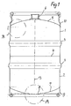
- the beer keg shown in Fig. 1 in a vertical section a so-called keg, consists of two sections 1 and 2, which are deep-drawn from metal and are firmly connected to each other after the incorporation of the rolling rings 3 in the central plane via the weld 4.
- the bulged end wall 5 of part 1 is provided with a connection fitting 6.
- a barrel sump 8 is formed in the bulging end wall 7 of part 2 forming the base part.
- a base ring 9 or 10 is welded to both the base part 7 and the end wall 5 forming the cover part.
- the overpressure protection arranged in the barrel sump 8, that is to say in area A, is explained in more detail with reference to the enlarged illustration in FIGS. 2 and 3.
- a dome-shaped depression 12 was embossed into the surface of the barrel sump 8 which is delimited by the circular edge line 11 during the manufacture of the base part 7.
- a tearing groove 14 has been machined into the surfaces delimited by the edge line 11 using a cutting tool that runs coaxially to the barrel axis 13 and surrounds a circular area and is only interrupted in the region of the dome-shaped depression 12.
- the tear groove 14 is approximately wedge-shaped, as can be seen by the line 15 of the groove wall extended outwards in the drawing.
- the residual thickness of the barrel wall remaining in the groove base is now designed so that the barrel withstands a predetermined test pressure of, for example, 3 bar, but that the barrel wall on the tear groove 14 tears open when the barrel internal pressure is increased to, for example, 35 bar. Since the tear groove 14 has the same depth over its entire length, local inhomogeneities in the material of the barrel wall have no influence on the start of the crack, so that it is only important to incorporate the depth of the tear groove 14 precisely enough.
- the tear groove 14 can be stamped in place of a cutting shape with the help of a cutting-like embossing tool during the manufacture of the barrel bottom.
- a depression 12 is incorporated, since it is then possible to work with a self-contained cutting tool which also covers the area of the depression 12, but nevertheless edge pressures which would occur in the area of the ends in the case of an unclosed embossing tool , be avoided.
- a circular circumferential bead 17 is incorporated into the area of the barrel sump 8, into the base of which a tear groove 14 is in turn incorporated.
- This embodiment takes advantage of the fact that under the influence of the internal pressure acting vertically on the inside wall of the barrel (arrow 18), the surface 19 enclosed by the bead 17 is curved outwards when a minimum pressure is exceeded, while at the same time due to the curvature of the part 19 surrounding bottom part 7 also become effective from the edge region in the direction of the surface (arrow 20), so that the weakened container wall in the area of the tear groove 14 tears open due to the superimposition of tensile and bending forces under the influence of the notch effect.
- the tear groove 14 can be closed in itself or, as shown, can be interrupted.
- the tear groove 14 can either be wedge-shaped in cross-section, as shown, or can also be trapezoidal in cross-section. This has particularly in With regard to the superimposition of tensile and bending stresses in the event of overpressure, this results in a more favorable tear behavior.
- FIG. 6 shows in section the dome-shaped lid part 5 of the keg shown in FIG. 1.
- the cover part merges with a radius of curvature R1 into the essentially cylindrical side wall 22, which is considerably smaller than the radius of curvature R2 of the spherical cap part.
- This edge region 21 is surrounded on the outside by the welded-on stand ring 10.
- the circular tear groove 14 is worked in with a rotating cutting tool, the path of movement of the tool being laid such that it runs out in the edge region 21 of the curvature of the end wall 5 which has the smaller radius of curvature R1, so that it is viewed from above 7 shows an open circular contour.
- FIG. 9 shows a dome or punctiform recess 12 incorporated into the surface, in which then Working in the tear groove 14 with the aid of a cutting but also an embossing tool, the tool can run out and the tear groove 14 enclosing the surface area 16 is again interrupted, and a corresponding "joint" is formed here, the wall thickness of which is not weakened. If the permissible maximum pressure is exceeded, the surface area 16 then opens outwards, as shown in dashed lines. The gaseous pressure medium escaping here is deflected upward from the inside of the standing ring 10, so that the reaction forces acting on the container are essentially directed towards the ground. In this embodiment too, the tear groove 14 has practically a constant depth over its full length.
Landscapes
- Engineering & Computer Science (AREA)
- Mechanical Engineering (AREA)
- Rigid Containers With Two Or More Constituent Elements (AREA)
- Safety Valves (AREA)
- Containers Opened By Tearing Frangible Portions (AREA)
Applications Claiming Priority (2)
| Application Number | Priority Date | Filing Date | Title |
|---|---|---|---|
| DE3737977 | 1987-11-08 | ||
| DE19873737977 DE3737977A1 (de) | 1987-11-08 | 1987-11-08 | Behaelter mit integrierter ueberdrucksicherung |
Publications (2)
| Publication Number | Publication Date |
|---|---|
| EP0318657A1 true EP0318657A1 (fr) | 1989-06-07 |
| EP0318657B1 EP0318657B1 (fr) | 1992-04-22 |
Family
ID=6340099
Family Applications (1)
| Application Number | Title | Priority Date | Filing Date |
|---|---|---|---|
| EP88115536A Expired - Lifetime EP0318657B1 (fr) | 1987-11-08 | 1988-09-22 | Récipient à protection incorporée contre la surpression |
Country Status (2)
| Country | Link |
|---|---|
| EP (1) | EP0318657B1 (fr) |
| DE (2) | DE3737977A1 (fr) |
Cited By (2)
| Publication number | Priority date | Publication date | Assignee | Title |
|---|---|---|---|---|
| EP1293476A3 (fr) * | 2001-09-14 | 2003-07-02 | SCHÄFER WERKE GmbH | Distributeur de boissons |
| FR2875765A1 (fr) * | 2004-09-30 | 2006-03-31 | Peugeot Citroen Automobiles Sa | Dispositif de protection d'un reservoir d'eau de lavage des elements vitres d'un vehicule automobile |
Families Citing this family (5)
| Publication number | Priority date | Publication date | Assignee | Title |
|---|---|---|---|---|
| DE9303113U1 (de) * | 1993-03-05 | 1994-04-14 | Schäfer Werke GmbH, 57290 Neunkirchen | Druckbelastbarer Metallbehälter |
| DE4437748C2 (de) * | 1994-09-20 | 1996-07-04 | Schuetz Werke Gmbh Co Kg | Verfahren zum Rekonditionieren von genormten Spundfässern aus Kunststoff |
| DE102010044338B4 (de) | 2009-09-08 | 2023-05-04 | SCHäFER WERKE GMBH | Behälter mit einer Sicherheitsberststelle |
| DE102012106643B8 (de) * | 2012-07-23 | 2014-03-27 | Progress-Werk Oberkirch Ag | Verfahren zum Herstellen eines Druckbehälters sowie derartiger Druckbehälter |
| US8939314B1 (en) | 2013-07-30 | 2015-01-27 | Progress-Werk-Oberkirch AG | Method for producing a pressure vessel and pressure vessel |
Citations (3)
| Publication number | Priority date | Publication date | Assignee | Title |
|---|---|---|---|---|
| GB1007594A (en) * | 1961-03-24 | 1965-10-13 | Grundy Teddington Ltd | Improvements in metal casks and like containers and methods of making same |
| EP0104056A2 (fr) * | 1982-09-20 | 1984-03-28 | Sexton Can Company, Inc. | Dispositif détendeur de pression |
| EP0228149A2 (fr) * | 1985-12-30 | 1987-07-08 | Amoco Corporation | Valve anti-surpression |
Family Cites Families (3)
| Publication number | Priority date | Publication date | Assignee | Title |
|---|---|---|---|---|
| AT52598B (de) * | 1910-12-05 | 1912-03-11 | Berlin Anhaltische Maschb Ag | Tank für feuergefährliche Flüssigkeiten. |
| US3484817A (en) * | 1967-11-07 | 1969-12-16 | Black Swalls & Bryson Inc | Safety pressure relief device |
| DE3533406A1 (de) * | 1985-08-23 | 1987-03-05 | Schaefer Werke Gmbh | Druckfester metallbehaelter zur aufnahme von fluessigkeiten |
-
1987
- 1987-11-08 DE DE19873737977 patent/DE3737977A1/de active Granted
-
1988
- 1988-09-22 DE DE8888115536T patent/DE3870416D1/de not_active Expired - Lifetime
- 1988-09-22 EP EP88115536A patent/EP0318657B1/fr not_active Expired - Lifetime
Patent Citations (3)
| Publication number | Priority date | Publication date | Assignee | Title |
|---|---|---|---|---|
| GB1007594A (en) * | 1961-03-24 | 1965-10-13 | Grundy Teddington Ltd | Improvements in metal casks and like containers and methods of making same |
| EP0104056A2 (fr) * | 1982-09-20 | 1984-03-28 | Sexton Can Company, Inc. | Dispositif détendeur de pression |
| EP0228149A2 (fr) * | 1985-12-30 | 1987-07-08 | Amoco Corporation | Valve anti-surpression |
Cited By (2)
| Publication number | Priority date | Publication date | Assignee | Title |
|---|---|---|---|---|
| EP1293476A3 (fr) * | 2001-09-14 | 2003-07-02 | SCHÄFER WERKE GmbH | Distributeur de boissons |
| FR2875765A1 (fr) * | 2004-09-30 | 2006-03-31 | Peugeot Citroen Automobiles Sa | Dispositif de protection d'un reservoir d'eau de lavage des elements vitres d'un vehicule automobile |
Also Published As
| Publication number | Publication date |
|---|---|
| EP0318657B1 (fr) | 1992-04-22 |
| DE3737977C2 (fr) | 1991-12-05 |
| DE3737977A1 (de) | 1989-05-24 |
| DE3870416D1 (de) | 1992-05-27 |
Similar Documents
| Publication | Publication Date | Title |
|---|---|---|
| DE3532395C2 (fr) | ||
| DE60209807T2 (de) | Dosendeckel | |
| DE69023626T2 (de) | Eingekerbte Umkehrberstscheibe. | |
| DE2828341A1 (de) | Ueberdrucksicherung mit einer reversions-bruchscheibe | |
| EP0161565A2 (fr) | Capuchon de fermeture | |
| DE60027771T2 (de) | Sicherheitventil mit sollbruchstelle | |
| DE2525047A1 (de) | Leicht zu oeffnender behaelterteil und verfahren und vorrichtung zu dessen herstellung | |
| CH656104A5 (de) | Kunststoffbehaelter mit deckel. | |
| DE1501747C3 (de) | Druckbehälter mit Abgabeventil und einer Sicherheitseinrichtung zur Druckentlastung | |
| DE2341077C3 (de) | Blechbehälterdeckel mit mindestens einem in den Behälter bewegbaren biegesteifen Verschlußteil | |
| DE3876696T2 (de) | Umkehrberstscheibe zur druckentlastung. | |
| EP0488936A2 (fr) | Générateur de gaz, en particulier générateur de gaz tubulaire pour un coussin gonflable | |
| DE2335342A1 (de) | Sicherheitsvorrichtung zum begrenzen des druckes eines fluids | |
| EP0390222B1 (fr) | Récipient avec bonde | |
| EP0318657B1 (fr) | Récipient à protection incorporée contre la surpression | |
| DE19754111B4 (de) | Stapelbarer Behälter für ein unter Druck stehendes Fluid | |
| DE3533406C2 (fr) | ||
| EP0686120B1 (fr) | Recipient en metal pouvant supporter une surpression interne | |
| DE68905791T2 (de) | Ein leicht zu oeffnender verschluss fuer duennblechdeckel von dosen und dergleichen. | |
| DE3702557A1 (de) | Druckentlastungsverfahren und berstvorrichtung | |
| EP0825131B1 (fr) | Récipient pour distribution de liquides par pression interne de gaz | |
| EP0825131A2 (fr) | Récipient pour distribution de liquides par pression interne de gaz | |
| DE69501181T2 (de) | Doppelventil | |
| DE2708505A1 (de) | Ueberdrucksicherung mit konkav-konvexem bruchglied | |
| DE69926360T2 (de) | Umkehrberstscheibe |
Legal Events
| Date | Code | Title | Description |
|---|---|---|---|
| PUAI | Public reference made under article 153(3) epc to a published international application that has entered the european phase |
Free format text: ORIGINAL CODE: 0009012 |
|
| AK | Designated contracting states |
Kind code of ref document: A1 Designated state(s): BE DE FR GB NL |
|
| GBC | Gb: translation of claims filed (gb section 78(7)/1977) | ||
| TCNL | Nl: translation of patent claims filed | ||
| EL | Fr: translation of claims filed | ||
| 17P | Request for examination filed |
Effective date: 19890622 |
|
| 17Q | First examination report despatched |
Effective date: 19910709 |
|
| GRAA | (expected) grant |
Free format text: ORIGINAL CODE: 0009210 |
|
| RAP1 | Party data changed (applicant data changed or rights of an application transferred) |
Owner name: BLEFA GMBH |
|
| AK | Designated contracting states |
Kind code of ref document: B1 Designated state(s): BE DE FR GB NL |
|
| REF | Corresponds to: |
Ref document number: 3870416 Country of ref document: DE Date of ref document: 19920527 |
|
| ET | Fr: translation filed | ||
| GBT | Gb: translation of ep patent filed (gb section 77(6)(a)/1977) | ||
| PLBI | Opposition filed |
Free format text: ORIGINAL CODE: 0009260 |
|
| 26 | Opposition filed |
Opponent name: THIELMANN AG KOMMANDITGESELLSCHAFT Effective date: 19930122 |
|
| NLR1 | Nl: opposition has been filed with the epo |
Opponent name: THIELMANN AG. KG. |
|
| PLBN | Opposition rejected |
Free format text: ORIGINAL CODE: 0009273 |
|
| STAA | Information on the status of an ep patent application or granted ep patent |
Free format text: STATUS: OPPOSITION REJECTED |
|
| 27O | Opposition rejected |
Effective date: 19940408 |
|
| NLR2 | Nl: decision of opposition | ||
| PGFP | Annual fee paid to national office [announced via postgrant information from national office to epo] |
Ref country code: GB Payment date: 19950811 Year of fee payment: 8 |
|
| PGFP | Annual fee paid to national office [announced via postgrant information from national office to epo] |
Ref country code: BE Payment date: 19950818 Year of fee payment: 8 |
|
| PGFP | Annual fee paid to national office [announced via postgrant information from national office to epo] |
Ref country code: FR Payment date: 19950821 Year of fee payment: 8 |
|
| PGFP | Annual fee paid to national office [announced via postgrant information from national office to epo] |
Ref country code: NL Payment date: 19950823 Year of fee payment: 8 |
|
| PG25 | Lapsed in a contracting state [announced via postgrant information from national office to epo] |
Ref country code: GB Effective date: 19960922 |
|
| PG25 | Lapsed in a contracting state [announced via postgrant information from national office to epo] |
Ref country code: FR Effective date: 19960930 Ref country code: BE Effective date: 19960930 |
|
| BERE | Be: lapsed |
Owner name: BLEFA G.M.B.H. Effective date: 19960930 |
|
| PG25 | Lapsed in a contracting state [announced via postgrant information from national office to epo] |
Ref country code: NL Effective date: 19970401 |
|
| PGFP | Annual fee paid to national office [announced via postgrant information from national office to epo] |
Ref country code: DE Payment date: 19970423 Year of fee payment: 9 |
|
| GBPC | Gb: european patent ceased through non-payment of renewal fee |
Effective date: 19960922 |
|
| NLV4 | Nl: lapsed or anulled due to non-payment of the annual fee |
Effective date: 19970401 |
|
| REG | Reference to a national code |
Ref country code: FR Ref legal event code: ST |
|
| REG | Reference to a national code |
Ref country code: FR Ref legal event code: ST |
|
| PG25 | Lapsed in a contracting state [announced via postgrant information from national office to epo] |
Ref country code: DE Free format text: LAPSE BECAUSE OF THE APPLICANT RENOUNCES Effective date: 19980214 |