EP0318690A2 - Aussenrückblickspiegel für Kraftfahrzeuge - Google Patents
Aussenrückblickspiegel für Kraftfahrzeuge Download PDFInfo
- Publication number
- EP0318690A2 EP0318690A2 EP88117460A EP88117460A EP0318690A2 EP 0318690 A2 EP0318690 A2 EP 0318690A2 EP 88117460 A EP88117460 A EP 88117460A EP 88117460 A EP88117460 A EP 88117460A EP 0318690 A2 EP0318690 A2 EP 0318690A2
- Authority
- EP
- European Patent Office
- Prior art keywords
- rearview mirror
- mirror according
- housing
- pyramid
- exterior
- Prior art date
- Legal status (The legal status is an assumption and is not a legal conclusion. Google has not performed a legal analysis and makes no representation as to the accuracy of the status listed.)
- Granted
Links
Images


Classifications
-
- B—PERFORMING OPERATIONS; TRANSPORTING
- B60—VEHICLES IN GENERAL
- B60R—VEHICLES, VEHICLE FITTINGS, OR VEHICLE PARTS, NOT OTHERWISE PROVIDED FOR
- B60R1/00—Optical viewing arrangements; Real-time viewing arrangements for drivers or passengers using optical image capturing systems, e.g. cameras or video systems specially adapted for use in or on vehicles
- B60R1/02—Rear-view mirror arrangements
- B60R1/06—Rear-view mirror arrangements mounted on vehicle exterior
Definitions
- the invention relates to an exterior rear view mirror for motor vehicles according to the preamble of patent claim 1.
- Such mirrors have been known for a long time.
- the basic shape of a flatter pyramid can be seen, for example, from DE-0S 16 30 338 or DE-0S 30 32 019, while the basic shape of a more elongated cone is described, for example, by DE-GM 66 04 966.
- DE-GM 66 04 966 the previously known exterior rear-view mirrors have already been designed from an aerodynamic point of view, the drag coefficient does not yet meet today's requirements.
- the dead water area is also at the height of the side windows, which leads to an undesirable contamination of these windows.
- the invention has for its object to provide an external rear view mirror of the type required, with which the air resistance can be reduced even further, with a further reduction in the contamination of the side windows to be achieved.
- the tip of the oblique pyramid or the oblique cone has a particularly favorable effect as a flow divider for the air flow that occurs in the lower area of the roof pillar, where the exterior rearview mirror is usually arranged.
- the air flowing in above the front hood and pushed away from the windshield not only flows horizontally around the front roof pillar, it also has a downward movement component, in particular in the area of the roof pillar root.
- the air flowing towards the housing of the exterior rearview mirror in this way is opposed by the exterior rearview mirror according to the invention, due to its ideal inflow distribution, little air resistance.
- Fig. 1 of the drawing the front left roof post 1 is indicated, which connects to the windshield 2.
- the arm 5 of the housing 6 of the exterior rearview mirror is fastened to the door 3, which is also only indicated, by means of a conventional triangular holding part 4.
- the housing 6 accommodates the mirror glass and can be folded down towards the vehicle contour 7 in a manner not shown with a specific force.
- the housing 6 is at a distance from the vehicle contour 7 indicated in dash-dotted lines, so that air can flow past on its inside.
- the housing 6 has the shape of an oblique pyramid.
- the rounded tip 8 of the oblique pyramid which is directed forward in the direction of travel, is provided in the upper corner area of the housing 6 facing the vehicle contour 7.
- the transition from the sides just mentioned is formed by rounded dividing edges 12, 13 and 14, which divide the air flow flowing approximately centrally to the tip 8 into essentially three partial flows.
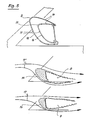
- the contour 15 representing a section at the inner end region of the housing 6 and the contour 16 representing a section in the outer region thereof.
- the upper side 10 is inclined from the upper front to the lower rear.
- the front side 11 is inclined rearwards downwards and the inner side 9 is inclined rearwards outwards.
- the air flowing in via the front hood of the vehicle and flowing downward from the windshield to the side and in the region of the exterior rearview mirror, which is illustrated by the flow arrows 17, is directed with particularly low resistance around the housing 6 of the exterior rearview mirror.
- the front side 11 - as seen in plan view - is additionally inclined to the rear in its outer area.
- the design of the housing 6 of the exterior rearview mirror described here enables a significant reduction in the partial drag coefficient generated by the exterior rearview mirror.
- Relatively small dead water zones 18 are formed, which are also directed downward in the area near the vehicle, which furthermore favors keeping the side window clear of swirled dirty water droplets.
- the housing 6 is connected to the body or door 3 of the vehicle via an approximately horizontal support arm 5, which merges into a generally triangular holding part 4.
- the support arm 5 has a wing profile-like cross section and can be subdivided and contain an articulated mechanism which enables the housing to be folded down towards the vehicle contour 7 when a certain shock load occurs.
- the profile cross section of the support arm 5 is directed from the top up to the bottom and thus also the flow direction of the body-near air flow (flow arrows 17 ') well adapted. Also in the region of the support arm 5, a very small dead water area 18 'is thus formed.
Landscapes
- Engineering & Computer Science (AREA)
- Multimedia (AREA)
- Mechanical Engineering (AREA)
- Rear-View Mirror Devices That Are Mounted On The Exterior Of The Vehicle (AREA)
- Optical Elements Other Than Lenses (AREA)
Abstract
Description
- Die Erfindung bezieht sich auf einen Außenrückblickspiegel für Kraftfahrzeuge nach dem Oberbegriff des Patentanspruchs 1.
- Derartige Spiegel sind seit langem bekannt. Die Grundform einer flacheren Pyramide geht beispielsweise aus der DE-0S 16 30 338 oder aus der DE-0S 30 32 019 hervor, während die Grundform eines mehr langgestreckten Kegels beispielsweise durch das DE-GM 66 04 966 vorbeschrieben ist. Die vorbekannten Außenrückblickspiegel sind zwar wohl schon auch nach aerodynamischen Gesichtspunkten gestaltet worden, doch befriedigt der Luftwiderstandsbeiwert noch nicht den heutigen Ansprüchen. Das Totwassergebiet liegt darüber hinaus in der Höhe der Seitenscheiben, was zu einer unerwünschten Verschmutzung dieser Scheiben führt.
- Es ist zwar schon erkannt worden, daß hier das Vorsehen eines Strömungskanals zwischen dem Gehäuse des Außenrückblickspiegels und der benachbarten Fahrzeugkontur Abhilfe schaffen kann (DE-0S 33 43 197 oder DE-0S 35 00 196), wobei in einem Fall auch schon durch zwei Tragarme des Gehäuses ein nach unten gerichteter Strömungskanal zum besseren Schmutzfernhalten der Seitenscheiben vorgesehen wurde. Auch diese Außenrückblickspiegel sind aerodynamisch noch verbesserungswürdig.
- Der Erfindung liegt die Aufgabe zugrunde, einen Außenrückblickspiegel der vorausgesetzten Gattung zu schaffen, mit dem der Luftwiderstand noch weiter vermindert werden kann, wobei auch eine weitere Verringerung der Verschmutzung der Seitenscheiben erreicht werden soll.
- Diese Aufgabe wird erfindungsgemäß mit einem Außenrückblickspiegel nach dem Oberbegriff des Patentanspruchs 1 durch die im Kennzeichen dieses Patentanspruchs angegebenen Merkmale gelöst. Dank dieser Maßnahmen wirkt die Spitze der schiefen Pyramide bzw. des schiefen Kegels besonders günstig als Strömungsteiler für die Luftströmung, die sich im unteren Bereich des Dachpfostens einstellt, wo in der Regel der Außenrückblickspiegel angeordnet ist. Die oberhalb der Fronthaube anströmende und von der Windschutzscheibe abgedrängte Luft strömt nicht nur horizontal um den vorderen Dachpfosten herum, sie hat insbesondere im Bereich der Dachpfostenwurzel auch eine nach unten gerichtete Bewegungskomponente. Der in dieser Art auf das Gehäuse des Außenrückblickspiegels zuströmenden Luft setzt der erfindungsgemäße Außenrückblickspiegel durch seine ideale Zuströmungsaufteilung wenig Luftwiderstand entgegen. Nach der Aufweitung der Umströmung erfolgt durch leicht konvergierend nach innen geneigte Abströmtangenten an den Gehäusehinterkanten eine allmähliche Zusammenführung der Strömung, die das eingeschlossene, ruhige Totwassergebiet begrenzt. Dabei wird auch der zwischen der Gehäuseinnenseite und der angrenzenden Fahrzeugkontur bzw. der Seitenscheibe freigehaltende Strömungsquerschnitt besonders wirksam durchströmt, so daß das Totwassergebiet sehr gut nach hinten, unten und in den Bereich des Türseitenbleches unterhalb der Seitenscheibe abgedrängt werden kann. Die Seitenscheiben bleiben daher sauber.
- Die Erfindung sowie weitere vorteilhafte Einzelheiten der Erfindung sind im folgenden anhand eines in der Zeichnung dargestellten Ausführungsbeispiels näher erläutert. Es zeigen
- Fig. 1 eine perspektivische Ansicht von vorne außen auf den neuen Außenrückblickspiegel;
- Fig. 2 eine teils schematisierte Seitenansicht;
- Fig. 3 eine leicht perspektivische Ansicht von hinten innen;
- Fig. 4 eine Draufsicht auf den neuen Außenrückblickspiegel und
- Fig. 5 eine Schnittdarstellung nach den Linien V-V in Iig. 4 mit dazugehörigen seitlichen Schemaansichten.
- In Fig. 1 der Zeichnung ist der vordere linke Dachpfosten 1 angedeutet, der sich an die Windschutzscheibe 2 anschließt. An der ebenfalls lediglich angedeuteten Tür 3 ist über ein übliches, dreieckiges Halteteil 4 der Tragarm 5 des Gehäuses 6 des Außenrückblickspiegels befestigt. Das Gehäuse 6 nimmt das Spiegelglas auf und ist in einer nicht näher dargestellten Weise bei einer bestimmten Krafteinwirkung zu der Fahrzeugkontur 7 hin abklappbar.
- Wie man insbesondere in Fig. 4 erkennt, hat das Gehäuse 6 von der in strichpunktierten Linien angedeuteten Fahrzeugkontur 7 einen Abstand, so daß an seiner Innenseite Luft vorbeiströmen kann.
- Das Gehäuse 6 hat die Form einer schiefen Pyramide. Die in Fahrtrichtung nach vorn gerichtete, abgerundete Spitze 8 der schiefen Pyramide ist im oberen und der Fahrzeugkontur 7 zugewandten Eckbereich des Gehäuses 6 vorgesehen. In dem an die abgerundete Spitze 8 angrenzenden Bereich des Gehäuses 6 handelt es sich um eine dreiseitige schiefe Pyramide mit einer der Fahrzeugkontur 7 zugekehrten Innenseite 9, einer Oberseite 10 und einer Vorderseite 11. Den Übergang der eben erwähnten Seiten bilden abgerundete Teilungskanten 12, 13 und 14, die den etwa zentral auf die Spitze 8 zuströmenden Luftstrom in im wesentlichen drei Teilströme aufteilen.
- In Fig. 5 sind vertikale Teilschnitte durch das Spiegelgehäuse dargestellt, wobei die Kontur 15 einen Schnitt am inneren Endbereich des Gehäuses 6 darstellt und die Kontur 16 einen Schnitt in dessen äußerem Bereich. Man erkennt, daß zumindest im inneren Bereich des Gehäuses 6 die Oberseite 10 von vorne oben nach hinten unten geneigt ist. Weiterhin ist die Vorderseite 11 nach hinten unten geneigt und die Innenseite 9 ist hinten nach außen geneigt. Auf diese Weise wird die über die Fronthaube des Fahrzeugs anströmende und von der Windschutzscheibe zur Seite sowie im Bereich des Außenrückblickspiegels auch nach unten strömende, durch die Strömungspfeile 17 veranschaulichte Luft besonders widerstandsarm um das Gehäuse 6 des Außenrückblickspiegels gelenkt. Hierzu ist es weiterhin günstig, wenn die Vorderseite 11 - in Draufsicht gesehen - zusätzlich noch in ihrem äußeren Bereich nach hinten geneigt ist.
- Die hier beschriebene Gestaltung des Gehäuses 6 des Außenrückblickspiegels ermöglicht eine deutliche Erniedrigung des vom Außenrückblickspiegel erzeugten Teil-Widerstandsbeiwerts. Es bilden sich relativ geringe, im fahrzeugnahen Bereich außerdem nach unten gerichtete Totwasserzonen 18 aus, was darüber hinaus das Freihalten der Seitenscheibe von verwirbelten Schmutzwassertröpfchen begünstigt.
- Wie man insbesondere in Fig. 1 und 3 erkennt, ist das Gehäuse 6 über einen annähernd horizontalen Tragarm 5 mit der Karosserie bzw. der Tür 3 des Fahrzeugs verbunden, der in ein in der Regel dreieckiges Halteteil 4 übergeht. Der Tragarm 5 hat einen flügelprofilähnlichen Querschnitt und kann unterteilt sein sowie einen Gelenkmechanismus enthalten, der das Abklappen des Gehäuses zur Fahrzeugkontur 7 hin ermöglicht, wenn eine bestimmte Stoßbelastung auftritt.
- Gemäß Fig. 2 ist der Profilquerschnitt des Tragarms 5 von vorne oben nach hinten unten gerichtet und damit der Strömungsrichtung der karosserienahen Luftströmung (Strömungspfeile 17′) ebenfalls gut angepaßt. Auch im Bereich des Tragarms 5 bildet sich somit ein nur sehr kleines Totwassergebiet 18′ aus.
Claims (10)
Applications Claiming Priority (2)
| Application Number | Priority Date | Filing Date | Title |
|---|---|---|---|
| DE19873737167 DE3737167A1 (de) | 1987-11-03 | 1987-11-03 | Aussenrueckblickspiegel fuer kraftfahrzeuge |
| DE3737167 | 1987-11-03 |
Publications (3)
| Publication Number | Publication Date |
|---|---|
| EP0318690A2 true EP0318690A2 (de) | 1989-06-07 |
| EP0318690A3 EP0318690A3 (en) | 1989-07-19 |
| EP0318690B1 EP0318690B1 (de) | 1992-12-16 |
Family
ID=6339621
Family Applications (1)
| Application Number | Title | Priority Date | Filing Date |
|---|---|---|---|
| EP19880117460 Expired - Lifetime EP0318690B1 (de) | 1987-11-03 | 1988-10-20 | Aussenrückblickspiegel für Kraftfahrzeuge |
Country Status (3)
| Country | Link |
|---|---|
| EP (1) | EP0318690B1 (de) |
| DE (2) | DE3737167A1 (de) |
| ES (1) | ES2037178T3 (de) |
Cited By (1)
| Publication number | Priority date | Publication date | Assignee | Title |
|---|---|---|---|---|
| EP2607172A1 (de) * | 2011-12-20 | 2013-06-26 | Nissan Motor Manufacturing (UK) Ltd. | Seitenrückspiegelanordnung |
Family Cites Families (7)
| Publication number | Priority date | Publication date | Assignee | Title |
|---|---|---|---|---|
| US3993281A (en) * | 1975-08-29 | 1976-11-23 | Mccarroll R A | Safety side mirror for vehicles |
| US4200327A (en) * | 1978-08-04 | 1980-04-29 | General Motors Corporation | Air-deflecting arrangement |
| SE444152B (sv) * | 1982-11-29 | 1986-03-24 | Saab Scania Ab | Backspegel for fordon |
| US4538851A (en) * | 1984-01-18 | 1985-09-03 | General Motors Corporation | Aerodynamic rear view mirror |
| DE3429493C1 (de) * | 1984-08-10 | 1985-12-05 | Daimler-Benz Ag, 7000 Stuttgart | Außenrückblickspiegel für Fahrzeuge, insbesondere für Kraftwagen |
| US4759620A (en) * | 1985-12-25 | 1988-07-26 | Honda Giken Kogyo Kabushiki Kaisha | Back-mirror device for small-sized vehicles |
| US4645170A (en) * | 1986-03-24 | 1987-02-24 | Parker-Hannifin Corporation | Outside rear view mirror |
-
1987
- 1987-11-03 DE DE19873737167 patent/DE3737167A1/de not_active Withdrawn
-
1988
- 1988-10-20 DE DE8888117460T patent/DE3876764D1/de not_active Expired - Lifetime
- 1988-10-20 ES ES198888117460T patent/ES2037178T3/es not_active Expired - Lifetime
- 1988-10-20 EP EP19880117460 patent/EP0318690B1/de not_active Expired - Lifetime
Cited By (1)
| Publication number | Priority date | Publication date | Assignee | Title |
|---|---|---|---|---|
| EP2607172A1 (de) * | 2011-12-20 | 2013-06-26 | Nissan Motor Manufacturing (UK) Ltd. | Seitenrückspiegelanordnung |
Also Published As
| Publication number | Publication date |
|---|---|
| DE3876764D1 (de) | 1993-01-28 |
| DE3737167A1 (de) | 1989-05-18 |
| EP0318690A3 (en) | 1989-07-19 |
| ES2037178T3 (es) | 1993-06-16 |
| EP0318690B1 (de) | 1992-12-16 |
Similar Documents
| Publication | Publication Date | Title |
|---|---|---|
| EP0853562B1 (de) | Wischblatt für eine scheibenwischvorrichtung eines fahrzeuges | |
| EP0895889B2 (de) | Cabriofahrzeug | |
| DE19734169B4 (de) | Nutzfahrzeug mit einem Spiegel im Frontbereich | |
| DE4040839A1 (de) | Innenrueckblickspiegel fuer kraftfahrzeuge | |
| DE4445414B4 (de) | Verbindungsstück für eine Scheibenwischvorrichtung eines Kraftfahrzeuges | |
| DE3343197C2 (de) | ||
| DE2511290A1 (de) | Nicht verschmutzender rueckspiegel | |
| EP0199010A2 (de) | Aerodynamische Vorrichtung für einen Personenwagen | |
| EP0396930B1 (de) | Omnibus mit wenigstens drei Aussenspiegeln | |
| DE69206329T2 (de) | Scheibenwischer für ein Kraftfahrzeug, versehen mit einem aerodynamischen Windabweiser. | |
| DE3739591C2 (de) | ||
| EP0190715B1 (de) | Fahrzeug-Flügeltür | |
| EP0318690B1 (de) | Aussenrückblickspiegel für Kraftfahrzeuge | |
| DE3809220C2 (de) | ||
| DE3116628A1 (de) | Im heckbereich eines personenkraftfahrzeuges mit heckscheibe angeordneter abweiser fuer schmutz, regen und dgl. | |
| DE3631467C2 (de) | Luftleitvorrichtung für Vollheck-Kraftfahrzeuge | |
| DE10156019B4 (de) | Verstellbares Fahrzeugdach für ein Cabriolet-Fahrzeug | |
| DE3115150A1 (de) | "aerodynamisch wirkende vorrichtung zur verringerung der seitenwindempfindlichkeit eines fahrzeugs" | |
| DE2735330A1 (de) | Anordnung zum sauberhalten der seitenscheibe eines kraftfahrzeuges | |
| DE2552915A1 (de) | Aussenrueckblickspiegel fuer fahrzeuge | |
| DE19825703B4 (de) | Vorrichtung zur Verringerung der Seitenscheibenverschmutzung an einem Kraftfahrzeug | |
| DE102005057619A1 (de) | Nutzfahrzeug mit Öffnung im Dachspoiler | |
| DE10052837A1 (de) | Kraftfahrzeug | |
| DE102005019778A1 (de) | Spiegelgehäuse | |
| DE10246980B4 (de) | Reinigungsvorrichtung für eine Scheibe eines Fahrzeugs |
Legal Events
| Date | Code | Title | Description |
|---|---|---|---|
| PUAI | Public reference made under article 153(3) epc to a published international application that has entered the european phase |
Free format text: ORIGINAL CODE: 0009012 |
|
| PUAL | Search report despatched |
Free format text: ORIGINAL CODE: 0009013 |
|
| AK | Designated contracting states |
Kind code of ref document: A2 Designated state(s): DE ES FR GB IT SE |
|
| AK | Designated contracting states |
Kind code of ref document: A3 Designated state(s): DE ES FR GB IT SE |
|
| 17P | Request for examination filed |
Effective date: 19890616 |
|
| 17Q | First examination report despatched |
Effective date: 19910801 |
|
| GRAA | (expected) grant |
Free format text: ORIGINAL CODE: 0009210 |
|
| AK | Designated contracting states |
Kind code of ref document: B1 Designated state(s): DE ES FR GB IT SE |
|
| ET | Fr: translation filed | ||
| GBT | Gb: translation of ep patent filed (gb section 77(6)(a)/1977) |
Effective date: 19921216 |
|
| REF | Corresponds to: |
Ref document number: 3876764 Country of ref document: DE Date of ref document: 19930128 |
|
| ITF | It: translation for a ep patent filed | ||
| RAP4 | Party data changed (patent owner data changed or rights of a patent transferred) |
Owner name: BAYERISCHE MOTOREN WERKE AKTIENGESELLSCHAFT |
|
| REG | Reference to a national code |
Ref country code: ES Ref legal event code: FG2A Ref document number: 2037178 Country of ref document: ES Kind code of ref document: T3 |
|
| PLBE | No opposition filed within time limit |
Free format text: ORIGINAL CODE: 0009261 |
|
| STAA | Information on the status of an ep patent application or granted ep patent |
Free format text: STATUS: NO OPPOSITION FILED WITHIN TIME LIMIT |
|
| 26N | No opposition filed | ||
| EAL | Se: european patent in force in sweden |
Ref document number: 88117460.1 |
|
| REG | Reference to a national code |
Ref country code: GB Ref legal event code: IF02 |
|
| PGFP | Annual fee paid to national office [announced via postgrant information from national office to epo] |
Ref country code: ES Payment date: 20070927 Year of fee payment: 20 |
|
| PGFP | Annual fee paid to national office [announced via postgrant information from national office to epo] |
Ref country code: DE Payment date: 20071129 Year of fee payment: 20 |
|
| PGFP | Annual fee paid to national office [announced via postgrant information from national office to epo] |
Ref country code: IT Payment date: 20071030 Year of fee payment: 20 |
|
| PGFP | Annual fee paid to national office [announced via postgrant information from national office to epo] |
Ref country code: SE Payment date: 20071004 Year of fee payment: 20 |
|
| PGFP | Annual fee paid to national office [announced via postgrant information from national office to epo] |
Ref country code: GB Payment date: 20071031 Year of fee payment: 20 Ref country code: FR Payment date: 20071029 Year of fee payment: 20 |
|
| REG | Reference to a national code |
Ref country code: GB Ref legal event code: PE20 Expiry date: 20081019 |
|
| EUG | Se: european patent has lapsed | ||
| REG | Reference to a national code |
Ref country code: ES Ref legal event code: FD2A Effective date: 20081021 |
|
| PG25 | Lapsed in a contracting state [announced via postgrant information from national office to epo] |
Ref country code: ES Free format text: LAPSE BECAUSE OF EXPIRATION OF PROTECTION Effective date: 20081021 |
|
| PG25 | Lapsed in a contracting state [announced via postgrant information from national office to epo] |
Ref country code: GB Free format text: LAPSE BECAUSE OF EXPIRATION OF PROTECTION Effective date: 20081019 |