EP0318692B1 - Warnleuchte für Fahrzeuge - Google Patents
Warnleuchte für Fahrzeuge Download PDFInfo
- Publication number
- EP0318692B1 EP0318692B1 EP88117517A EP88117517A EP0318692B1 EP 0318692 B1 EP0318692 B1 EP 0318692B1 EP 88117517 A EP88117517 A EP 88117517A EP 88117517 A EP88117517 A EP 88117517A EP 0318692 B1 EP0318692 B1 EP 0318692B1
- Authority
- EP
- European Patent Office
- Prior art keywords
- light
- reflector
- shading plate
- warning light
- shading
- Prior art date
- Legal status (The legal status is an assumption and is not a legal conclusion. Google has not performed a legal analysis and makes no representation as to the accuracy of the status listed.)
- Expired - Lifetime
Links
- 230000003287 optical effect Effects 0.000 claims description 3
- 241000761557 Lamina Species 0.000 claims 1
- 230000004313 glare Effects 0.000 description 5
- 230000000694 effects Effects 0.000 description 3
- 241000446313 Lamella Species 0.000 description 1
- 238000005452 bending Methods 0.000 description 1
- 230000001419 dependent effect Effects 0.000 description 1
- 230000004907 flux Effects 0.000 description 1
- 239000011888 foil Substances 0.000 description 1
- 230000011664 signaling Effects 0.000 description 1
- 239000012780 transparent material Substances 0.000 description 1
Images
Classifications
-
- B—PERFORMING OPERATIONS; TRANSPORTING
- B60—VEHICLES IN GENERAL
- B60Q—ARRANGEMENT OF SIGNALLING OR LIGHTING DEVICES, THE MOUNTING OR SUPPORTING THEREOF OR CIRCUITS THEREFOR, FOR VEHICLES IN GENERAL
- B60Q1/00—Arrangement of optical signalling or lighting devices, the mounting or supporting thereof or circuits therefor
- B60Q1/26—Arrangement of optical signalling or lighting devices, the mounting or supporting thereof or circuits therefor the devices being primarily intended to indicate the vehicle, or parts thereof, or to give signals, to other traffic
- B60Q1/2611—Indicating devices mounted on the roof of the vehicle
Definitions
- the innovation relates to a warning light for vehicles, with a light-concentrating reflector located within a translucent, colored light hood, arranged on a rotating base, and a shading device arranged in the beam path between the reflector and the light hood.
- FR-A-1 185 191 proposes a warning light with a screen made of transparent material built into the light hood.
- the luminous flux emerging directly from the lamp is covered by a spherical cap.
- the signal light directed by the reflector is disadvantageously emitted, no longer in the horizontal direction, but obliquely downwards or upwards. Since the light that emits directly from the incandescent lamp is covered by the spherical cap, the warning light loses its signaling effect almost completely.
- the attachment of the screen over the entire outlet opening of the reflector has such a disadvantage that a large part of the light is absorbed.
- the object of the innovation is to design the warning lamp for vehicles in such a way that glare to the vehicle occupants is avoided without having to accept a reduction in the light emerging from the reflector. If possible, only that part of the light that causes glare to the vehicle occupants should be shaded.
- the innovations should enable all existing warning lights with a rotating reflector to be retrofitted with little effort and simple assembly, and the new shading device can be manufactured as an inexpensive stamped part.
- a shading plate divided into slats running parallel to the horizontal central plane forms the shading device, which is firmly connected to the reflector, and that the shading plate is arranged in the lower half of the reflector opening.
- the shading plate only partially covers the reflector and only the lower half. This has the effect that, despite the movement of the vehicle about the transverse axis, not only is warning light emitted obliquely upwards or downwards, but also in the horizontal direction by the part of the directly emitted light which is not affected by the shading device.
- Another advantageous embodiment of the innovation is such that the shading plate has only a single lamella, as a result of which the weight of the shading plate is even lighter with regard to imbalance and can be produced with less effort.
- the shading plate shades rays of the directly emerging light beam at an angle ( ⁇ ) which begins approximately 45 ° below the horizontal plane lying in the optical axis of the reflector and extends approximately to the vertical.
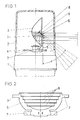
- a warning lamp is shown, the housing of which consists of a lamp base (1) and a translucent light hood (2).
- a rotatably mounted base (4) which is connected to an electric motor, not shown, is arranged below the light hood (2) and on the lower part of the lamp (1).
- the reflector (3) is covered on its lower exit half by a shading plate (5) and its slats (6) pointing in the horizontal plane.
- the shading plate (5) is firmly connected to the reflector (3) and the base (4) by bending folds (7).
- the light (9), which is emitted by the light source arranged in the focal point (8) of the reflector (3) is directed at the angle ( ⁇ ) with shading by the slats (6) of the shading plate (5) at the outlet through the light hood (2) prevented.
- the new design of the shader with regard to the number of its slats is dependent on the desired ratio of the continuous to the absorbed light.
- the surface design of a slat must always be taken into account depending on the size of the reflector and the angle of the directly emitted light.
Landscapes
- Engineering & Computer Science (AREA)
- Mechanical Engineering (AREA)
- Non-Portable Lighting Devices Or Systems Thereof (AREA)
Description
- Die Neuerung bezieht sich auf eine Warnleuchte für Fahrzeuge, mit einem innerhalb einer lichtdurchlässigen, farbigen Lichthaube befindlichen, auf einem rotierenden Sockel angeordneten, lichtbündelnden Reflektor und einem im Strahlengang zwischen dem Reflektor und der Lichthaube angeordneten Abschatter.
- Sonderfahrzeuge mit derartigen Warnleuchten sind in der Regel bei der Polizei, Feuerwehr oder ähnlichen Einrichtungen bekannt. Es ergeben sich jedoch bei Fahrzeugen der neueren Generation, an den aus verschiedenen Gründen extrem geneigten Frontscheiben, Blenderscheinungen durch vagabundierendes Licht, speziell durch Reflektion an Scheibenwischern, Zierleisten oder dergleichen.
- In der FR-A-1 185 191 wird eine Warnleuchte, mit in die Lichthaube eingebauten Blendschirm aus transparentem Material vorgeschlagen. Gleichzeitig wird der direkt aus der Lampe austretende Lichtstrom durch eine Kalotte abgedeckt. Bei einer Bewegung des Fahrzeugs um seine Querachse erfolgt nachteiligerweise die Abstrahlung des vom Reflektor gerichteten Signallichts, nicht mehr in horizontaler Richtung, sondern schräg nach unten oder oben. Da das direkt aus der Glühlampe ausfallende Licht durch die Kalotte abgedeckt ist, verliert die Warnleuchte ihre Signalwirkung fast vollständig. Außerdem wirkt sich die Anbringung des Blendschirms über die gesamte Austrittsöffnung des Reflektors derartig nachteilig aus, daß ein großer Teil des Lichtes absorbiert wird.
- Eine andere, aus dem DE-U-85 26 331 bezeichnete Variante, die Blendung zu unterdrücken, ist die Verwendung von Folien, welche entweder auf der Innen- oder Außenseite der farbigen Lichthaube angebracht sind. Abgesehen von der möglichen Beschädigung durch Waschanlagen bei Außenmontage ist es nachteilig, daß eine nicht mehr genügende Lichtmenge die Warnleuchte verläßt, da nicht nur, wie gewünscht direkt aus der Glühlampe austretendes und deshalb Blendung verursachendes Licht abgeschirmt wird, sondern auch das durch den Reflektor horizontal ausgerichtete Licht. Bei Abschattung eines nur in Fahrtrichtung weisenden Sektors durch eine Folie oder Blendschirm macht sich nachteiligerweise eine dem Fahrzeug und speziell seiner Windschutzscheibe angepaßte Einbaulage der Warnleuchte erforderlich.
- Aufgabe der Neuerung ist es, die Warnleuchte für Fahrzeuge so auszubilden, daß eine Blendung der Fahrzeuginsassen vermieden wird, ohne dabei eine Reduzierung des aus dem Reflektor gerichtet austretenden Lichts in Kauf nehmen zu müssen. Dabei soll möglichst nur der Teil des Lichtes abgeschattet werden, der die Blendung der Fahrzeuginsassen hervorruft. Darüber hinaus sollen durch die Neuerungen alle bereits existierenden Warnleuchten mit rotierendem Reflektor ohne großen Aufwand bei einfacher Montage nachgerüstet werden können, wobei der neuerungsgemäße Abschatter als kostengünstiges Stanzteil gefertigt werden kann.
- Diese Aufgabe wird gemäß der Neuerung dadurch gelöst, daß ein in parallel zur horizontalen Mittelebene verlaufende Lamellen unterteiltes Abschattungsblech den Abschatter bildet, das mit dem Reflektor fest verbunden ist, und daß das Abschattungsblech in der unteren Hälfte der Reflektoröffnung angeordnet ist. Dies bewirkt, daß trotz Bewegung des Fahrzeuges um die Querachse nicht nur Warnlicht nach schräg oben oder unten abgegeben wird, sondern auch durch den vom Abschatter nicht betroffenen Teil des direkt abgestrahlten Lichtes in horizontaler Richtung.
- Weiterhin ist es von Vorteil, wenn das Abschattungsblech den Reflektor nur teilweise und zwar nur die untere Hälfte abdeckt. Dies bewirkt, daß trotz Bewegung des Fahrzeuges um die Querachse nicht nur Warnlicht nach schräg oben oder unten abgegeben wird, sondern auch durch den vom Abschatter nicht betroffenen Teil des direkt abgestrahlten Lichtes in horizontaler Richtung.
- Eine weitere vorteilhafte Ausführungsform der Neuerung ist derart, daß das Abschattungsblech nur eine einzige Lamelle aufweist, wodurch das Abschattungsblech in seinem Gewicht bezüglich einer Unwucht noch leichter ausfällt und mit geringerem Aufwand gefertigt werden kann.
- Ferner ist es von Vorteil, wenn das Abschattungsblech Strahlen des direkt ausfallenden Lichtbündels in einem Winkel (α) abschattet, der etwa 45 ° unterhalb der in der optischen Achse des Reflektors liegenden Horizontalebene beginnt und etwa bis zur Vertikalen geht.
- Die Neuerung ist in einer Zeichnung dargestellt, und zwar zeigt:
- Figur 1 eine Seitenansicht der Warnleuchte mit einer teilweise geschnittenen Lichthaube,
- Figur 2 das Abschattungsblech in Frontalansicht im unmontiertem Zustand.
- In der Zeichnung ist eine Warnleuchte dargestellt, deren Gehäuse aus einem Leuchtenunterteil (1) und einer lichtdurchlässigen Lichthaube (2) besteht. Unterhalb der Lichthaube (2) und auf dem Leuchtenunterteil (1) ist ein drehbar gelagerter Sockel (4) angeordnet, der mit einem nicht dargestellten E-Motor verbunden ist. An dem Sockel (4) ist ein Reflektor (3) mit einer nicht dargestellten Glühlampe befestigt. Der Reflektor (3) ist an seiner unteren Austrittshälfte von einem Abschattungsblech (5) und seinen in horizontaler Ebene weisenden Lamellen (6) abgedeckt. Durch Biegefalze (7) wird das Abschattungsblech (5) fest mit dem Reflektor (3) und dem Sockel (4) verbunden. Das, von der im Brennpunkt (8) des Reflektors (3) angeordneten Lichtquelle abgegebene, direkt nach außen gerichtete Licht (9) wird im Winkel (α) unter Abschattung durch die Lamellen (6) des Abschattungsblechs (5) am Austritt durch die Lichthaube (2) gehindert.
- Die neuerungsgemäße Ausführung des Abschatters hinsichtlich der Anzahl seiner Lamellen ist einmal abhängig vom angestrebten Verhältnis des durchgehenden zum absorbierten Licht. Dabei ist die flächenmäßige Gestaltung einer Lamelle stets in Abhängigkeit von der Größe des Reflektors und dem Winkel des direkt abgestrahlten Lichts zu berücksichtigen.
Claims (4)
- Warnleuchte für Fahrzeuge mit einem innerhalb einer lichtdurchlässigen, farbigen Lichthaube befindlichen, auf einem rotierenden Leuchtensockel angeordneten, lichtbündelnden Reflektor und einem im Strahlengang zwischen dem Reflektor und der Lichthaube angeordneten Abschatter, dadurch gekennzeichnet, daß ein in parallel zur horizontalen Mittelebene verlaufende Lamellen (6) unterteiltes Abschattungsblech (5) den Abschatter bildet, das mit dem Reflektor (3) fest verbunden ist, und daß das Abschattungsblech (5) in der unteren Hälfte der Reflektoröffnung angeordnet ist.
- Warnleuchte für Fahrzeuge nach Anspruch 1, dadurch gekennzeichnet, daß das Abschattungsblech (5) sich über die gesamte untere Hälfte des Reflektoröffnung (3) erstreckt.
- Warnleuchte für Fahrzeuge nach Anspruch 1, dadurch gekennzeichnet, daß das Abschattungsblech (5) mit nur einer Lamelle (6) versehen ist.
- Warnleuchte für Fahrzeuge nach einem der vorstehenden Ansprüche, dadurch gekennzeichnet, daß das Abschattungsblech (5) Strahlen des direkt ausfallenden Lichtbündels (9) in einem Winkel (α) abschattet, der etwa 45 ° unterhalb der in der optischen Achse des Reflektors liegenden Horizontalebene beginnt und etwa bis zur Vertikalen geht.
Applications Claiming Priority (2)
| Application Number | Priority Date | Filing Date | Title |
|---|---|---|---|
| DE8715822U | 1987-11-30 | ||
| DE8715822U DE8715822U1 (de) | 1987-11-30 | 1987-11-30 | Warnleuchte für Fahrzeuge |
Publications (2)
| Publication Number | Publication Date |
|---|---|
| EP0318692A1 EP0318692A1 (de) | 1989-06-07 |
| EP0318692B1 true EP0318692B1 (de) | 1992-01-29 |
Family
ID=6814595
Family Applications (1)
| Application Number | Title | Priority Date | Filing Date |
|---|---|---|---|
| EP88117517A Expired - Lifetime EP0318692B1 (de) | 1987-11-30 | 1988-10-21 | Warnleuchte für Fahrzeuge |
Country Status (2)
| Country | Link |
|---|---|
| EP (1) | EP0318692B1 (de) |
| DE (2) | DE8715822U1 (de) |
Family Cites Families (5)
| Publication number | Priority date | Publication date | Assignee | Title |
|---|---|---|---|---|
| GB136677A (en) * | 1919-01-09 | 1919-12-24 | Herbert Weld-Blundell | Improvements in or relating to Signal Lights for Motor Road Vehicles. |
| FR587069A (fr) * | 1924-10-09 | 1925-04-10 | Ecran à lames horizontales fixes pour phares d'automobiles | |
| FR618782A (fr) * | 1926-04-13 | 1927-03-18 | Phare anti-éblouissant | |
| FR864409A (fr) * | 1940-04-06 | 1941-04-26 | Lampe Yvel Anciens Etablisseme | Lampes de projecteurs pour véhicules, spécialement les automobiles, à répartition optimum du flux rayonné |
| DE8518587U1 (de) * | 1985-06-27 | 1985-08-14 | Westfälische Metall Industrie KG Hueck & Co, 4780 Lippstadt | Warnleuchte für Fahrzeuge |
-
1987
- 1987-11-30 DE DE8715822U patent/DE8715822U1/de not_active Expired
-
1988
- 1988-10-21 DE DE8888117517T patent/DE3868242D1/de not_active Expired - Lifetime
- 1988-10-21 EP EP88117517A patent/EP0318692B1/de not_active Expired - Lifetime
Also Published As
| Publication number | Publication date |
|---|---|
| DE8715822U1 (de) | 1988-02-11 |
| DE3868242D1 (de) | 1992-03-12 |
| EP0318692A1 (de) | 1989-06-07 |
Similar Documents
| Publication | Publication Date | Title |
|---|---|---|
| DE2732895C3 (de) | Scheinwerfer, insbesondere für Kraftfahrzeuge | |
| DE3634996C2 (de) | ||
| EP0113365B1 (de) | Scheinwerfer mit verstellbarem reflektor für kraftfahrzeuge | |
| DE10003061A1 (de) | Beleuchtungssystem für Kraftfahrzeuge mit einer Tagessignallichtfunktion | |
| DE19824053A1 (de) | Beleuchtungseinrichtung für Fahrzeuge | |
| DE3214523C2 (de) | Scheinwerferanordnung | |
| DE3239754C2 (de) | ||
| DE3306481A1 (de) | Lichtabgabevorrichtung fuer kraftfahrzeuge | |
| DE3427398C2 (de) | ||
| DE602004010766T2 (de) | Umgebungsbeleuchtungssystem für Kraftfahrzeuge, Beleuchtungseinrichtung, Fahrzeug und Rollo mit einem solchen System | |
| EP0318692A1 (de) | Warnleuchte für Fahrzeuge | |
| DE3922830C2 (de) | Lichtabgabeoptik für Kraftfahrzeugleuchten | |
| DE69513789T2 (de) | Zusatzwarnleuchteanordnung in Heckspoiler eines Fahrzeuges | |
| WO2001027526A1 (de) | Scheinwerfer für ein kraftfahrzeug | |
| EP2981436B1 (de) | Beleuchtungseinrichtung für ein hinteres kennzeichenschild eines kraftfahrzeugs | |
| DE918433C (de) | Abblendeinrichtung an Scheinwerfer-, Nebel- und Kurvenlampen von Fahrzeugen | |
| DE2908821C2 (de) | Farbig strahlende Eckleuchte für ein Fahrzeug | |
| DE2725953C3 (de) | Scheinwerfer, insbesondere für Kraftfahrzeuge | |
| DE3430824A1 (de) | Sonnenschutz | |
| DE913281C (de) | Leuchte mit Blendschutz, insbesondere fuer Verkehrswege | |
| DE3625938C2 (de) | ||
| DE69001995T2 (de) | Trennvorrichtung für den Fahrgastraum eines Fahrzeugs mit Heckklappe. | |
| DE102023000760B4 (de) | Heckleuchtenanordnung für ein Fahrzeug | |
| DE2835808A1 (de) | Signalleuchte, insbesondere fuer kraftfahrzeuge | |
| DE2743777A1 (de) | Signalleuchte, insbesondere fuer kraftfahrzeuge |
Legal Events
| Date | Code | Title | Description |
|---|---|---|---|
| PUAI | Public reference made under article 153(3) epc to a published international application that has entered the european phase |
Free format text: ORIGINAL CODE: 0009012 |
|
| AK | Designated contracting states |
Kind code of ref document: A1 Designated state(s): BE DE FR GB IT NL |
|
| 17P | Request for examination filed |
Effective date: 19891031 |
|
| 17Q | First examination report despatched |
Effective date: 19910314 |
|
| ITF | It: translation for a ep patent filed | ||
| GRAA | (expected) grant |
Free format text: ORIGINAL CODE: 0009210 |
|
| AK | Designated contracting states |
Kind code of ref document: B1 Designated state(s): BE DE FR GB IT NL |
|
| REF | Corresponds to: |
Ref document number: 3868242 Country of ref document: DE Date of ref document: 19920312 |
|
| GBT | Gb: translation of ep patent filed (gb section 77(6)(a)/1977) | ||
| ET | Fr: translation filed | ||
| PGFP | Annual fee paid to national office [announced via postgrant information from national office to epo] |
Ref country code: NL Payment date: 19921031 Year of fee payment: 5 |
|
| PLBE | No opposition filed within time limit |
Free format text: ORIGINAL CODE: 0009261 |
|
| STAA | Information on the status of an ep patent application or granted ep patent |
Free format text: STATUS: NO OPPOSITION FILED WITHIN TIME LIMIT |
|
| 26N | No opposition filed | ||
| PG25 | Lapsed in a contracting state [announced via postgrant information from national office to epo] |
Ref country code: NL Effective date: 19940501 |
|
| NLV4 | Nl: lapsed or anulled due to non-payment of the annual fee | ||
| PGFP | Annual fee paid to national office [announced via postgrant information from national office to epo] |
Ref country code: GB Payment date: 19940920 Year of fee payment: 7 |
|
| PGFP | Annual fee paid to national office [announced via postgrant information from national office to epo] |
Ref country code: FR Payment date: 19941007 Year of fee payment: 7 |
|
| PGFP | Annual fee paid to national office [announced via postgrant information from national office to epo] |
Ref country code: BE Payment date: 19941011 Year of fee payment: 7 |
|
| PGFP | Annual fee paid to national office [announced via postgrant information from national office to epo] |
Ref country code: DE Payment date: 19941104 Year of fee payment: 7 |
|
| PG25 | Lapsed in a contracting state [announced via postgrant information from national office to epo] |
Ref country code: GB Effective date: 19951021 |
|
| PG25 | Lapsed in a contracting state [announced via postgrant information from national office to epo] |
Ref country code: BE Effective date: 19951031 |
|
| BERE | Be: lapsed |
Owner name: HELLA K.G. HUECK & CO. Effective date: 19951031 |
|
| GBPC | Gb: european patent ceased through non-payment of renewal fee |
Effective date: 19951021 |
|
| PG25 | Lapsed in a contracting state [announced via postgrant information from national office to epo] |
Ref country code: FR Effective date: 19960628 |
|
| PG25 | Lapsed in a contracting state [announced via postgrant information from national office to epo] |
Ref country code: DE Effective date: 19960702 |
|
| REG | Reference to a national code |
Ref country code: FR Ref legal event code: ST |
|
| PG25 | Lapsed in a contracting state [announced via postgrant information from national office to epo] |
Ref country code: IT Free format text: LAPSE BECAUSE OF NON-PAYMENT OF DUE FEES;WARNING: LAPSES OF ITALIAN PATENTS WITH EFFECTIVE DATE BEFORE 2007 MAY HAVE OCCURRED AT ANY TIME BEFORE 2007. THE CORRECT EFFECTIVE DATE MAY BE DIFFERENT FROM THE ONE RECORDED. Effective date: 20051021 |