EP0318712A1 - Dispositif de connexion pour raccorder un plancher en béton à une colonne, et bâtiment - Google Patents
Dispositif de connexion pour raccorder un plancher en béton à une colonne, et bâtiment Download PDFInfo
- Publication number
- EP0318712A1 EP0318712A1 EP88118231A EP88118231A EP0318712A1 EP 0318712 A1 EP0318712 A1 EP 0318712A1 EP 88118231 A EP88118231 A EP 88118231A EP 88118231 A EP88118231 A EP 88118231A EP 0318712 A1 EP0318712 A1 EP 0318712A1
- Authority
- EP
- European Patent Office
- Prior art keywords
- support
- preferably according
- column
- concrete
- edge support
- Prior art date
- Legal status (The legal status is an assumption and is not a legal conclusion. Google has not performed a legal analysis and makes no representation as to the accuracy of the status listed.)
- Granted
Links
Images


Classifications
-
- E—FIXED CONSTRUCTIONS
- E04—BUILDING
- E04B—GENERAL BUILDING CONSTRUCTIONS; WALLS, e.g. PARTITIONS; ROOFS; FLOORS; CEILINGS; INSULATION OR OTHER PROTECTION OF BUILDINGS
- E04B5/00—Floors; Floor construction with regard to insulation; Connections specially adapted therefor
- E04B5/43—Floor structures of extraordinary design; Features relating to the elastic stability; Floor structures specially designed for resting on columns only, e.g. mushroom floors
-
- E—FIXED CONSTRUCTIONS
- E04—BUILDING
- E04C—STRUCTURAL ELEMENTS; BUILDING MATERIALS
- E04C5/00—Reinforcing elements, e.g. for concrete; Auxiliary elements therefor
- E04C5/01—Reinforcing elements of metal, e.g. with non-structural coatings
- E04C5/06—Reinforcing elements of metal, e.g. with non-structural coatings of high bending resistance, i.e. of essentially three-dimensional [3D] extent, e.g. lattice girders
- E04C5/0645—Shear reinforcements, e.g. shearheads for floor slabs
Definitions
- the present invention relates to a connecting device for connecting a concrete ceiling to a support and a structure with at least one device.
- a column head for connecting a solid concrete ceiling to a steel profile column with a vertical passage for utility lines has become known, in which construction the head part of the steel profile column is provided with vertical, wing-like steel sheets.
- an anchoring part is provided, which consists of rows of headed dowels which are welded to the wing-like steel sheets of the steel profile support.
- This prop head avoids peak loads, which is particularly due to the anchoring part that is made up of head there is bolting, is achieved.
- This column head can only be used for steel profile columns, the basic idea disclosed is therefore not to be used for pure iron-reinforced concrete structures.
- the headed dowels used are only used for laying on and not for mechanical connection with concrete reinforcing bars.
- a reinforced concrete ceiling with at least one vertical support in which the connection of the ceiling and the support or supports at or at each connection point is formed by a horizontally arranged element made of steel profile and having at least two angles to one another.
- the free legs of this element are connected to one another by at least one steel link. Concrete-free space for the passage of lines exists between the legs of the horizontal element and the associated steel connecting link.
- the prior art also includes a metallic column knob, which serves as a connecting element between a supporting column, on which it is fastened, and an armored concrete slab, in which slab it is cast.
- This column knob consists of several rods, which are welded together and which circumscribe a polygon, the ends of the rods protruding from this polygon being self-supporting. These bars or profiles are provided with pins pointing towards the inside of the polygon, which are used for anchoring in the concrete.
- a building is also part of the prior art, in which a mushroom has a central opening for inserting a support from above.
- the plate in the middle opening is subsequently connected to the mushroom, e.g. welded.
- the present invention aims to provide a connecting device which, compared to the prior art, has a low steel consumption, creates advantageous force relationships in the area of supporting the ceiling on the support and is environmentally friendly.
- Such a connecting device is characterized by the wording of one of the claims.
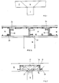
- FIG. 1 shows a support 1 with a concrete ceiling 2, in which construction no special measures for transferring forces from the concrete ceiling 2 into the support 1 are provided, that is to say in particular also no support head.
- the well-known eruption 4 then occurs, which can cause the ceiling to collapse.
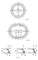
- FIGS. 2 and 3 shows a support 16 with a frame, which serves as an edge support 19 and is made of flat steel, glass fiber reinforced plastic or the like. Furthermore, outer and inner composite means 20 and 24 are arranged in a hedgehog-like manner projecting outwards and inwards from the edge carrier 19.
- the force is transferred from the inwardly projecting composite means 24 to the support 16 via a concrete pressure strut 27.
- Any moments as well as forces not taken over by concrete pressure struts can be transferred from beams using a cross 17.
- the shapes are square, rectangular, polygonal, circular, oval or other shapes are provided.
- Fig. 13 shows sections, among others. 2 and 4, in different versions.
- Edge supports 19 and 28 with or without additional supports 17 arranged in a cross or laid in the diagonals can be used as main structures.
- Shapes can be used for these flat or wide flat sheets, double-T or T-rolled profiles or other types of composite profiles and composite structures made of appropriate materials.
- the edge beams 19, 28, shown here as flat bars or Z-profiles, can also be designed as L-profiles, as box profiles or in any composition or as composite structures.
- the edge girder 19 with the composite means 20 is concreted in a concrete ceiling 18, as is analogous, for example, with reference to FIG. 2 and 3 is explained.
- the ceiling 18 is reinforced by means of reinforcing steels 30. From the illustration it can be seen how the U-shaped reinforcing steel is connected to the edge support 19 via the composite means 20.
- Flat or wide flat sheet metal is normally used for the head plates.
- Their shape can be square, rectangular, circular or star-shaped. But it is also possible without constructing these head plates and dimensioning the crosses accordingly.
- the devices according to the invention allow hori zonal and vertical recesses in the ceiling. They are particularly suitable for medium to large loads, but are material and therefore cost-saving for them. They form complete units with a relatively small installation weight and are inexpensive in every respect. They also comply with the SIA 160, 162 standard.
- the inner connection means 24 must be closer to the upper end plane of the ceiling, which is normal to the support, than the outer connection means 20, so that the pressure forces introduced into the pressure strut form a minimum inclination angle ⁇ with this end plane, which is greater than 25 according to SIA standards ° should be. If this angle becomes too small, several frames with composite materials must be provided to ensure that the forces are applied at an angle> 25 ° to the support.
- the new construction explained in detail offers the greatest possible degree of safety and improves the bending strength in the contact area. In addition, it enables perfect reinforcement management and thus optimal force transmission.
Landscapes
- Engineering & Computer Science (AREA)
- Architecture (AREA)
- Civil Engineering (AREA)
- Structural Engineering (AREA)
- Physics & Mathematics (AREA)
- Electromagnetism (AREA)
- Joining Of Building Structures In Genera (AREA)
- Working Measures On Existing Buildindgs (AREA)
- Connection Or Junction Boxes (AREA)
- Building Environments (AREA)
- Conveying And Assembling Of Building Elements In Situ (AREA)
Priority Applications (1)
| Application Number | Priority Date | Filing Date | Title |
|---|---|---|---|
| AT88118231T ATE72001T1 (de) | 1987-11-30 | 1988-11-02 | Verbindungsvorrichtung zum anschliessen einer betondecke an eine stuetze sowie bauwerk. |
Applications Claiming Priority (2)
| Application Number | Priority Date | Filing Date | Title |
|---|---|---|---|
| CH4653/87 | 1987-11-30 | ||
| CH465387 | 1987-11-30 |
Publications (2)
| Publication Number | Publication Date |
|---|---|
| EP0318712A1 true EP0318712A1 (fr) | 1989-06-07 |
| EP0318712B1 EP0318712B1 (fr) | 1992-01-22 |
Family
ID=4280128
Family Applications (1)
| Application Number | Title | Priority Date | Filing Date |
|---|---|---|---|
| EP88118231A Expired - Lifetime EP0318712B1 (fr) | 1987-11-30 | 1988-11-02 | Dispositif de connexion pour raccorder un plancher en béton à une colonne, et bâtiment |
Country Status (4)
| Country | Link |
|---|---|
| EP (1) | EP0318712B1 (fr) |
| AT (1) | ATE72001T1 (fr) |
| DE (1) | DE3868025D1 (fr) |
| NO (1) | NO884885D0 (fr) |
Cited By (10)
| Publication number | Priority date | Publication date | Assignee | Title |
|---|---|---|---|---|
| GB2235221A (en) * | 1989-08-21 | 1991-02-27 | Square Grip Ltd | Shearhead |
| EP0557731A1 (fr) * | 1992-01-28 | 1993-09-01 | Fundia Betoniteräkset Oy Ab | Armature pour un panneau à béton |
| WO1995028534A1 (fr) * | 1994-04-13 | 1995-10-26 | Zellner, Wilhelm | Bande a goujons pour barres relevees |
| WO1997036067A1 (fr) * | 1996-03-26 | 1997-10-02 | Sicon S.R.O. | Joint d'elements de construction en beton |
| RU2163959C2 (ru) * | 1996-03-26 | 2001-03-10 | Зикон С.Р.О. | Соединение конструктивных бетонных элементов |
| EP1180565A1 (fr) | 2000-08-08 | 2002-02-20 | Philippe Menetrey | Armature flexible de connexion pour le renforcement de structures en béton |
| DE19741509B4 (de) * | 1997-09-20 | 2004-03-11 | Stahl + Verbundbau Gesellschaft für industrielles Bauen m.b.H. | Stützenkopfverbreiterung als Durchstanzbewehrung in Stahlbetonplatten |
| DE102004005916A1 (de) * | 2004-02-06 | 2005-09-01 | Tue, Nguyen Viet, Prof. Dr.-Ing.habil. | Einbauteil für Beton zur Traglasterhöhung bei Druckbelastung |
| AT503475B1 (de) * | 2006-03-23 | 2009-01-15 | Katzenberger Baustoffindustrie | Flachdecke aus bewehrtem ortbeton und/oder betonfertigelementen |
| US20110094182A1 (en) * | 2008-05-19 | 2011-04-28 | Jeom Han KIM | Stiffener for connecting prestressed concrete beam and method of constructing structure using the same |
Citations (7)
| Publication number | Priority date | Publication date | Assignee | Title |
|---|---|---|---|---|
| CH382950A (de) * | 1964-04-23 | 1964-10-15 | Geilinger & Co | Abstützvorrichtung einer Eisenbetondecke |
| CH430128A (de) * | 1965-10-19 | 1967-02-15 | Geilinger & Co | Eisenbetondecke |
| DE2108524A1 (de) * | 1971-02-23 | 1973-05-10 | Bodo Rasch | System fuer rohbauten - bestehend aus elementen in pilzkonstruktion - industriell hergestellt und an der baustelle montiertgeeignet fuer eingeschossige und mehrgeschossige bauten - oder fuer vielgeschossige und hochhaeuser mittels uebergeordneter makrokonstruktion |
| CH596399A5 (en) * | 1975-09-12 | 1978-03-15 | Zwahlen & Mayr Sa | Metal cap to connect column and concrete slab |
| DE2920044A1 (de) * | 1979-05-18 | 1980-11-27 | Spannverbund Ges Fuer Verbundt | Stuetzenkopf |
| EP0128994A1 (fr) * | 1983-10-06 | 1984-12-27 | Geilinger AG | Procédé de fabrication d'un bâtiment |
| EP0163923A1 (fr) * | 1984-05-10 | 1985-12-11 | Wolfhart Dr.-Ing. Andrä | Liaison entre une dalle coulée sur place et des colonnes préfabriquées |
-
1988
- 1988-11-02 EP EP88118231A patent/EP0318712B1/fr not_active Expired - Lifetime
- 1988-11-02 AT AT88118231T patent/ATE72001T1/de not_active IP Right Cessation
- 1988-11-02 NO NO884885A patent/NO884885D0/no unknown
- 1988-11-02 DE DE8888118231T patent/DE3868025D1/de not_active Expired - Fee Related
Patent Citations (7)
| Publication number | Priority date | Publication date | Assignee | Title |
|---|---|---|---|---|
| CH382950A (de) * | 1964-04-23 | 1964-10-15 | Geilinger & Co | Abstützvorrichtung einer Eisenbetondecke |
| CH430128A (de) * | 1965-10-19 | 1967-02-15 | Geilinger & Co | Eisenbetondecke |
| DE2108524A1 (de) * | 1971-02-23 | 1973-05-10 | Bodo Rasch | System fuer rohbauten - bestehend aus elementen in pilzkonstruktion - industriell hergestellt und an der baustelle montiertgeeignet fuer eingeschossige und mehrgeschossige bauten - oder fuer vielgeschossige und hochhaeuser mittels uebergeordneter makrokonstruktion |
| CH596399A5 (en) * | 1975-09-12 | 1978-03-15 | Zwahlen & Mayr Sa | Metal cap to connect column and concrete slab |
| DE2920044A1 (de) * | 1979-05-18 | 1980-11-27 | Spannverbund Ges Fuer Verbundt | Stuetzenkopf |
| EP0128994A1 (fr) * | 1983-10-06 | 1984-12-27 | Geilinger AG | Procédé de fabrication d'un bâtiment |
| EP0163923A1 (fr) * | 1984-05-10 | 1985-12-11 | Wolfhart Dr.-Ing. Andrä | Liaison entre une dalle coulée sur place et des colonnes préfabriquées |
Cited By (14)
| Publication number | Priority date | Publication date | Assignee | Title |
|---|---|---|---|---|
| GB2235221B (en) * | 1989-08-21 | 1993-08-25 | Square Grip Ltd | Shearhead reinforcement |
| GB2235221A (en) * | 1989-08-21 | 1991-02-27 | Square Grip Ltd | Shearhead |
| EP0557731A1 (fr) * | 1992-01-28 | 1993-09-01 | Fundia Betoniteräkset Oy Ab | Armature pour un panneau à béton |
| US5867960A (en) * | 1994-04-13 | 1999-02-09 | Andrae; Hans-Peter | Dowel member for reinforcing concrete structures |
| WO1995028534A1 (fr) * | 1994-04-13 | 1995-10-26 | Zellner, Wilhelm | Bande a goujons pour barres relevees |
| US6058669A (en) * | 1996-03-26 | 2000-05-09 | Sicon, S.R.O. | Joint of concrete building elements |
| WO1997036067A1 (fr) * | 1996-03-26 | 1997-10-02 | Sicon S.R.O. | Joint d'elements de construction en beton |
| RU2163959C2 (ru) * | 1996-03-26 | 2001-03-10 | Зикон С.Р.О. | Соединение конструктивных бетонных элементов |
| DE19741509B4 (de) * | 1997-09-20 | 2004-03-11 | Stahl + Verbundbau Gesellschaft für industrielles Bauen m.b.H. | Stützenkopfverbreiterung als Durchstanzbewehrung in Stahlbetonplatten |
| EP1180565A1 (fr) | 2000-08-08 | 2002-02-20 | Philippe Menetrey | Armature flexible de connexion pour le renforcement de structures en béton |
| DE102004005916A1 (de) * | 2004-02-06 | 2005-09-01 | Tue, Nguyen Viet, Prof. Dr.-Ing.habil. | Einbauteil für Beton zur Traglasterhöhung bei Druckbelastung |
| AT503475B1 (de) * | 2006-03-23 | 2009-01-15 | Katzenberger Baustoffindustrie | Flachdecke aus bewehrtem ortbeton und/oder betonfertigelementen |
| US20110094182A1 (en) * | 2008-05-19 | 2011-04-28 | Jeom Han KIM | Stiffener for connecting prestressed concrete beam and method of constructing structure using the same |
| US8166717B2 (en) * | 2008-05-19 | 2012-05-01 | Cross Structural Consultant Co., Ltd. | Stiffener for connecting prestressed concrete beam and method of constructing structure using the same |
Also Published As
| Publication number | Publication date |
|---|---|
| NO884885D0 (no) | 1988-11-02 |
| ATE72001T1 (de) | 1992-02-15 |
| DE3868025D1 (de) | 1992-03-05 |
| EP0318712B1 (fr) | 1992-01-22 |
Similar Documents
| Publication | Publication Date | Title |
|---|---|---|
| DE1903129B2 (de) | Vorrichtung zum Anschließen eines Trägers an eine Betonstütze | |
| DE69221000T2 (de) | Gebäudekonstruktion | |
| EP0318712B1 (fr) | Dispositif de connexion pour raccorder un plancher en béton à une colonne, et bâtiment | |
| DE1609310A1 (de) | Gewoelbekonstruktion und Verfahren zu deren Errichtung | |
| EP4442917A2 (fr) | Structure primaire de coffrage composée de modules de structure plane constitués d'éléments | |
| DE4023465A1 (de) | Turmbauwerk | |
| DE102017114090B4 (de) | Verfahren zur Errichtung eines Gebäudes | |
| EP0023042B1 (fr) | Elément de plancher préfabriqué pour planchers de bâtiments | |
| DE102018131066A1 (de) | Bewehrung, Betonelement, Modulverbindung, Modulblock sowie Gebäude | |
| DE3403140C1 (de) | Tragwerk,insbesondere Brueckentragwerk | |
| DE3343721A1 (de) | Hoher, freistehender schornstein oder turm aus stahlbeton-fertigteilen | |
| CH651095A5 (de) | Bewehrungselement zur uebertragung von querkraeften in plattenartigen traggliedern, z.b. flachdecken. | |
| DE2649936A1 (de) | Behaelter aus stahlbeton und verfahren zur errichtung desselben | |
| EP0376167B1 (fr) | Mât pour un élévateur de construction, en particulier pour un élévateur à crémaillère | |
| EP1860246B1 (fr) | Elément de construction pour isolation thermique | |
| DE4000956C2 (de) | Element für den Großtafelbau aus Beton | |
| EP1630315A1 (fr) | Élément de construction pour armature de cisaillement et de poinconnement | |
| DE19636026C1 (de) | Hilfsrahmen für ein Nutzfahrzeug | |
| DE212021000266U1 (de) | Verbindungsstruktur zur Realisierung einer genauen Positionierung einer betongefüllten Raumstruktur aus mehrgliedrigen Stahlrohren und einer Tragplattform | |
| DE8027569U1 (de) | Platte, insbesondere deckenplatte aus beton | |
| DE2153495A1 (de) | Fertigteildeckenplatte fuer den montagebau | |
| DE3871960T2 (de) | Bodenstruktur fuer gebaeude. | |
| DE19903310A1 (de) | Verbundfertigteilträger sowie Verfahren zur Herstellung von Trägern, insbesondere für Brückenbauwerke | |
| DE19611200A1 (de) | Bewehrungsanordnung für Porenbeton-Bauteile | |
| DE2438376A1 (de) | Fachwerkplatte, insbesondere fuer versorgungsintensive bauten, und form zu deren herstellung |
Legal Events
| Date | Code | Title | Description |
|---|---|---|---|
| PUAI | Public reference made under article 153(3) epc to a published international application that has entered the european phase |
Free format text: ORIGINAL CODE: 0009012 |
|
| AK | Designated contracting states |
Kind code of ref document: A1 Designated state(s): AT BE CH DE ES FR GB GR IT LI LU NL SE |
|
| 17P | Request for examination filed |
Effective date: 19890717 |
|
| 17Q | First examination report despatched |
Effective date: 19900704 |
|
| GRAA | (expected) grant |
Free format text: ORIGINAL CODE: 0009210 |
|
| AK | Designated contracting states |
Kind code of ref document: B1 Designated state(s): AT BE CH DE ES FR GB GR IT LI LU NL SE |
|
| PG25 | Lapsed in a contracting state [announced via postgrant information from national office to epo] |
Ref country code: IT Free format text: LAPSE BECAUSE OF FAILURE TO SUBMIT A TRANSLATION OF THE DESCRIPTION OR TO PAY THE FEE WITHIN THE PRE;WARNING: LAPSES OF ITALIAN PATENTS WITH EFFECTIVE DATE BEFORE 2007 MAY HAVE OCCURRED AT ANY TIME BEFORE 2007. THE CORRECT EFFECTIVE DATE MAY BE DIFFERENT FROM THE ONE RECORDED.SCRIBED TIME-LIMIT Effective date: 19920122 Ref country code: GB Effective date: 19920122 Ref country code: SE Effective date: 19920122 Ref country code: BE Effective date: 19920122 Ref country code: NL Effective date: 19920122 Ref country code: ES Free format text: THE PATENT HAS BEEN ANNULLED BY A DECISION OF A NATIONAL AUTHORITY Effective date: 19920122 Ref country code: GR Free format text: LAPSE BECAUSE OF FAILURE TO SUBMIT A TRANSLATION OF THE DESCRIPTION OR TO PAY THE FEE WITHIN THE PRESCRIBED TIME-LIMIT Effective date: 19920122 |
|
| REF | Corresponds to: |
Ref document number: 72001 Country of ref document: AT Date of ref document: 19920215 Kind code of ref document: T |
|
| REF | Corresponds to: |
Ref document number: 3868025 Country of ref document: DE Date of ref document: 19920305 |
|
| ET | Fr: translation filed | ||
| NLV1 | Nl: lapsed or annulled due to failure to fulfill the requirements of art. 29p and 29m of the patents act | ||
| GBV | Gb: ep patent (uk) treated as always having been void in accordance with gb section 77(7)/1977 [no translation filed] | ||
| PG25 | Lapsed in a contracting state [announced via postgrant information from national office to epo] |
Ref country code: AT Effective date: 19921102 |
|
| PGFP | Annual fee paid to national office [announced via postgrant information from national office to epo] |
Ref country code: DE Payment date: 19921123 Year of fee payment: 5 |
|
| PGFP | Annual fee paid to national office [announced via postgrant information from national office to epo] |
Ref country code: FR Payment date: 19921125 Year of fee payment: 5 |
|
| PLBE | No opposition filed within time limit |
Free format text: ORIGINAL CODE: 0009261 |
|
| STAA | Information on the status of an ep patent application or granted ep patent |
Free format text: STATUS: NO OPPOSITION FILED WITHIN TIME LIMIT |
|
| PG25 | Lapsed in a contracting state [announced via postgrant information from national office to epo] |
Ref country code: LU Free format text: LAPSE BECAUSE OF NON-PAYMENT OF DUE FEES Effective date: 19921130 |
|
| 26N | No opposition filed | ||
| PGFP | Annual fee paid to national office [announced via postgrant information from national office to epo] |
Ref country code: CH Payment date: 19930129 Year of fee payment: 5 |
|
| PG25 | Lapsed in a contracting state [announced via postgrant information from national office to epo] |
Ref country code: LI Effective date: 19931130 Ref country code: CH Effective date: 19931130 |
|
| PG25 | Lapsed in a contracting state [announced via postgrant information from national office to epo] |
Ref country code: FR Effective date: 19940729 |
|
| REG | Reference to a national code |
Ref country code: CH Ref legal event code: PL |
|
| PG25 | Lapsed in a contracting state [announced via postgrant information from national office to epo] |
Ref country code: DE Effective date: 19940802 |
|
| REG | Reference to a national code |
Ref country code: FR Ref legal event code: ST |