EP0318726A2 - Outil pour enlever la queue de montage d'un insert fileté - Google Patents
Outil pour enlever la queue de montage d'un insert fileté Download PDFInfo
- Publication number
- EP0318726A2 EP0318726A2 EP88118530A EP88118530A EP0318726A2 EP 0318726 A2 EP0318726 A2 EP 0318726A2 EP 88118530 A EP88118530 A EP 88118530A EP 88118530 A EP88118530 A EP 88118530A EP 0318726 A2 EP0318726 A2 EP 0318726A2
- Authority
- EP
- European Patent Office
- Prior art keywords
- tube
- tool according
- piston
- flange
- tool
- Prior art date
- Legal status (The legal status is an assumption and is not a legal conclusion. Google has not performed a legal analysis and makes no representation as to the accuracy of the status listed.)
- Granted
Links
Images

Classifications
-
- B—PERFORMING OPERATIONS; TRANSPORTING
- B25—HAND TOOLS; PORTABLE POWER-DRIVEN TOOLS; MANIPULATORS
- B25B—TOOLS OR BENCH DEVICES NOT OTHERWISE PROVIDED FOR, FOR FASTENING, CONNECTING, DISENGAGING, OR HOLDING
- B25B27/00—Hand tools, specially adapted for fitting together or separating parts or objects whether or not involving some deformation, not otherwise provided for
- B25B27/14—Hand tools, specially adapted for fitting together or separating parts or objects whether or not involving some deformation, not otherwise provided for for assembling objects other than by press fit or detaching same
- B25B27/143—Hand tools, specially adapted for fitting together or separating parts or objects whether or not involving some deformation, not otherwise provided for for assembling objects other than by press fit or detaching same for installing wire thread inserts or tubular threaded inserts
-
- B—PERFORMING OPERATIONS; TRANSPORTING
- B23—MACHINE TOOLS; METAL-WORKING NOT OTHERWISE PROVIDED FOR
- B23D—PLANING; SLOTTING; SHEARING; BROACHING; SAWING; FILING; SCRAPING; LIKE OPERATIONS FOR WORKING METAL BY REMOVING MATERIAL, NOT OTHERWISE PROVIDED FOR
- B23D29/00—Hand-held metal-shearing or metal-cutting devices
- B23D29/002—Hand-held metal-shearing or metal-cutting devices for cutting wire or the like
Definitions
- the invention relates to a tool for removing the mounting pin of a wire thread insert according to the preamble of patent claim 1.
- Such wire thread inserts are used to line internal threads in parts whose building material is too soft to give a bolt made of hard material sufficient support or to allow repeated screwing in and out without damaging the internal thread.
- the inserts in the form of a wire coil are usually made with a larger diameter than the diameter of the internal thread to be lined, so that they embed themselves firmly in the threads under their own spring force. The inserts must therefore contract before or during insertion, i.e. be reduced in diameter.
- a continuous bolt is to be screwed into the threaded insert, the mounting pin must be removed.
- a predetermined breaking point in the form of a notch is provided at the end of the leading turn.
- the invention has for its object a tool To break off and remove the mounting pin, in particular from blind holes, so that the mounting pin is removed as quickly and reliably as possible.
- the already detached mounting pin is sucked out of an air stream through a tube inserted into the screwed-in wire coil.
- the air flow enters the blind bore through an annular gap between the outer circumference of the pipe and the inner circumference of the threaded insert, is deflected at the bottom of the blind hole and flows out through the inside of the pipe, the pin being carried safely.
- the tube immersed in the insert can preferably have a cross section which allows as much compressed air as possible to be supplied in a short time.
- the outer circumference of the tube can have a shape deviating from a circle in order to enlarge the inflow cross section for the compressed air.
- the outside of the tube can be provided with axial grooves or be flattened several times.
- the inner wall of the tube is preferably circular in order to facilitate the suctioning off of the pin.
- the mounting pin should be as short as possible.
- the pipe is also used to knock off the mounting pin.
- the compressed air required for suction also serves to actuate the tool for knocking off the pin.
- a piston is first actuated by the compressed air, which triggers the impact effect, whereupon a path for the compressed air is released to lead them into the blind hole. In this way, the working speed of the tool is significantly increased.
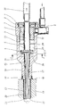
- the tool consists of a housing 1, a piston 2, a tube 3, a flange 4 fastened to the tube, a spring 5 arranged between the flange 4 and the piston 2, a compressed air connection 6 for a cylinder space 7, one Cylinder chamber 7 closing, with the housing 1 sealingly and releasably connected cover 8 and a rubber sleeve 10 on the front end of the housing 1st
- the ring piston 2 is slidably guided on the tube 3 and slides in the bore 11 of the housing 1.
- the ring piston 2 has a shoulder 12.
- the flange 4 is fastened on the tube 3 and is provided with radial grooves 14 on its side facing away from the annular piston 2. These grooves 14 open at their radially inner end into flats 15 of the tube 3, which can be seen in particular in FIG. 2.
- the tube 3 is guided in the bore 17 in the region of the front end 16 of the housing 1.
- the tool With a rubber sleeve 10, the tool is placed sealingly on the surface 18 of a workpiece 19, in whose inner bore 20 a wire thread insert 21 is inserted.
- the end of the wire thread insert 21 leading during insertion is bent as shown in FIG. 3 and forms an installation pin 22 which is as short as possible and already ends at a distance from the center axis of the insert.
- a predetermined breaking point in the form of a notch 23 is provided in order to facilitate the breaking off of the installation pin 22.
- the front end edge 25 of the tube 3 serves to knock off the mounting pin.
- the mode of operation is as follows: The tool is placed on the workpiece 19, the rubber sleeve 10 effecting a seal.
- the tube 3 is freely displaceable relative to the housing 1, and is pressed forward by the spring 5 and comes into contact with the mounting pin 22. Compressed air is then fed into the chamber 7 via the connection 6.
- the annular piston 2 is accelerated and strikes the flange 4 at high speed, which thus receives an axial feed at high speed together with the tube 3, as a result of which the pin 22 is knocked off the end edge 25 of the tube 3. This movement is ended as soon as the flange 4 has come into contact with the end wall 26 of the housing.
- the compressed air can pass from the chamber 7 into the space 29 and reaches the outside of the tube 3 via the radial grooves 14 in the flange 4 and via that in the axial direction extending flats 15 of the tube from the front end 16 of the housing.
- the air flow then enters the annular gap between the threaded insert 21 and the outside of the tube 3, is deflected at the end of the bore and becomes blown through the interior of the tube 3 with the entrained pin 22 to the outside.
- a hose 30 can be connected to dispose of the knocked off pins.
- the piston 2 is actuated by a brief burst of compressed air and the knocked-off pin is blown out. The piston 2 then returns to the starting position shown by means of the spring 5.
- the length of the tube 3 between the flange 4 and the pin to be knocked off must be chosen so that the stroke of the tube is sufficient to knock off the pin safely.
Landscapes
- Engineering & Computer Science (AREA)
- Mechanical Engineering (AREA)
- Percussive Tools And Related Accessories (AREA)
Applications Claiming Priority (2)
| Application Number | Priority Date | Filing Date | Title |
|---|---|---|---|
| DE3740560A DE3740560C2 (de) | 1987-11-30 | 1987-11-30 | Werkzeug zum Entfernen des Einbauzapfens eines Drahtgewindeeinsatzes |
| DE3740560 | 1987-11-30 |
Publications (3)
| Publication Number | Publication Date |
|---|---|
| EP0318726A2 true EP0318726A2 (fr) | 1989-06-07 |
| EP0318726A3 EP0318726A3 (en) | 1990-05-09 |
| EP0318726B1 EP0318726B1 (fr) | 1994-02-02 |
Family
ID=6341582
Family Applications (1)
| Application Number | Title | Priority Date | Filing Date |
|---|---|---|---|
| EP88118530A Expired - Lifetime EP0318726B1 (fr) | 1987-11-30 | 1988-11-07 | Outil pour enlever la queue de montage d'un insert fileté |
Country Status (2)
| Country | Link |
|---|---|
| EP (1) | EP0318726B1 (fr) |
| DE (3) | DE8717987U1 (fr) |
Cited By (5)
| Publication number | Priority date | Publication date | Assignee | Title |
|---|---|---|---|---|
| WO2002014025A1 (fr) * | 2000-08-11 | 2002-02-21 | Volvo Aero Corporation | Outil a main destine a detacher et a enlever des goupilles d'inserts fils helicoidaux constitues d'un fil metallique |
| EP1084800A3 (fr) * | 1999-09-15 | 2002-03-27 | Emhart Inc. | Outil motorisé pour filet hélicoidal |
| DE10305898A1 (de) * | 2003-02-13 | 2004-08-26 | Alstom Technology Ltd | Verfahren zum Einbauen von spiralförmigen Gewindeeinsätzen sowie Einbauwerkzeug zur Durchführung des Verfahrens |
| AT517436A1 (de) * | 2015-06-15 | 2017-01-15 | Fill Gmbh | Vorrichtung und Verfahren zum automatisierten Montieren von Gewindeeinsätzen in Bauteilen |
| CN117444328A (zh) * | 2019-11-18 | 2024-01-26 | 江苏科森医疗器械有限公司 | 薄壁管的内螺纹加工设备 |
Family Cites Families (3)
| Publication number | Priority date | Publication date | Assignee | Title |
|---|---|---|---|---|
| US3385380A (en) * | 1966-10-20 | 1968-05-28 | Vare Corp | Tang breakoff tool having spring actuated impact means |
| US3832772A (en) * | 1972-06-02 | 1974-09-03 | Shapiro Leonard U | Pneumatic hand tool |
| US4450736A (en) * | 1982-05-10 | 1984-05-29 | Bethlehem Steel Corp. | Impact-actuated gripping tool |
-
1987
- 1987-11-30 DE DE8717987U patent/DE8717987U1/de not_active Expired - Lifetime
- 1987-11-30 DE DE3740560A patent/DE3740560C2/de not_active Expired - Fee Related
-
1988
- 1988-11-07 EP EP88118530A patent/EP0318726B1/fr not_active Expired - Lifetime
- 1988-11-07 DE DE88118530T patent/DE3887655D1/de not_active Expired - Fee Related
Cited By (7)
| Publication number | Priority date | Publication date | Assignee | Title |
|---|---|---|---|---|
| EP1084800A3 (fr) * | 1999-09-15 | 2002-03-27 | Emhart Inc. | Outil motorisé pour filet hélicoidal |
| WO2002014025A1 (fr) * | 2000-08-11 | 2002-02-21 | Volvo Aero Corporation | Outil a main destine a detacher et a enlever des goupilles d'inserts fils helicoidaux constitues d'un fil metallique |
| DE10305898A1 (de) * | 2003-02-13 | 2004-08-26 | Alstom Technology Ltd | Verfahren zum Einbauen von spiralförmigen Gewindeeinsätzen sowie Einbauwerkzeug zur Durchführung des Verfahrens |
| US7340814B2 (en) | 2003-02-13 | 2008-03-11 | Alstom Technology Ltd. | Method of installing spiral threaded inserts and installation tool |
| AT517436A1 (de) * | 2015-06-15 | 2017-01-15 | Fill Gmbh | Vorrichtung und Verfahren zum automatisierten Montieren von Gewindeeinsätzen in Bauteilen |
| AT517436B1 (de) * | 2015-06-15 | 2017-04-15 | Fill Gmbh | Vorrichtung und Verfahren zum automatisierten Montieren von Gewindeeinsätzen in Bauteilen |
| CN117444328A (zh) * | 2019-11-18 | 2024-01-26 | 江苏科森医疗器械有限公司 | 薄壁管的内螺纹加工设备 |
Also Published As
| Publication number | Publication date |
|---|---|
| EP0318726A3 (en) | 1990-05-09 |
| DE3887655D1 (de) | 1994-03-17 |
| DE8717987U1 (de) | 1992-06-11 |
| EP0318726B1 (fr) | 1994-02-02 |
| DE3740560C2 (de) | 1994-05-26 |
| DE3740560A1 (de) | 1989-06-08 |
Similar Documents
| Publication | Publication Date | Title |
|---|---|---|
| EP4003649B1 (fr) | Collier de serrage | |
| EP0023672A1 (fr) | Elément pour la prise manuelle d'un instrument dentaire, l'élément étant muni d'une valve de commande de l'écoulement d'un courant de fluide | |
| EP0845092A1 (fr) | Systeme de raccordement haute pression | |
| DE4401622C2 (de) | Befestigungsvorrichtung für ein Montageglied einer Mutter-Schraube-Verbindung | |
| DE8121384U1 (de) | Loesbare rohrkupplung und patrone zur bildung einer solchen rohrkupplung | |
| DE10141560C2 (de) | Verfahren zur Herstellung eines fluidbetätigten Arbeitszylinders | |
| EP0318726B1 (fr) | Outil pour enlever la queue de montage d'un insert fileté | |
| EP3180543B1 (fr) | Élément vibrant muni d'un composant découplé | |
| EP0031125B1 (fr) | Raccord de tuyaux détachable | |
| DE3407315A1 (de) | Dehnspannwerkzeug mit kontrolleinrichtung | |
| DE4020669C2 (de) | Verfahren zur Herstellung eines Bremssattelgehäuses | |
| EP3383567B1 (fr) | Marteau de débourrage pour le débourrage de pièces coulées | |
| DE3148032C2 (fr) | ||
| DE3833882A1 (de) | Rammbohrgeraet | |
| DE2710830A1 (de) | Endarmatur fuer mehrkanalschlaeuche | |
| EP4554751A1 (fr) | Dispositif de réglage de longueur pour régler une position longitudinale d'un outil, appareil de serrage d'outil, et système et procédé comprenant le dispositif de réglage de longueur | |
| DE3024907A1 (de) | Haemmerwerkzeug fuer stumpf-befestiger | |
| DE3029621A1 (de) | Form- und nutvorrichtung fuer rohrenden | |
| DE102017000857A1 (de) | Zylinder-Kolben-Vorrichtung | |
| DE19681469B4 (de) | Hydraulisches Spielausgleichselement für einen Ventiltrieb einer Brennkraftmaschine | |
| EP1273793B1 (fr) | Dispositif de sécurité pour le blocage en rotation d'un élément à vis | |
| EP0491882B1 (fr) | Etancon hydraulique a plusieurs etages | |
| DE3014744A1 (de) | Hydraulische spannvorrichtung | |
| DE4441533C1 (de) | Dichtring | |
| EP0987475B1 (fr) | Soupape de pression résiduelle |
Legal Events
| Date | Code | Title | Description |
|---|---|---|---|
| PUAI | Public reference made under article 153(3) epc to a published international application that has entered the european phase |
Free format text: ORIGINAL CODE: 0009012 |
|
| AK | Designated contracting states |
Kind code of ref document: A2 Designated state(s): DE ES FR GB IT SE |
|
| PUAL | Search report despatched |
Free format text: ORIGINAL CODE: 0009013 |
|
| AK | Designated contracting states |
Kind code of ref document: A3 Designated state(s): DE ES FR GB IT SE |
|
| 17P | Request for examination filed |
Effective date: 19900904 |
|
| 17Q | First examination report despatched |
Effective date: 19920203 |
|
| GRAA | (expected) grant |
Free format text: ORIGINAL CODE: 0009210 |
|
| AK | Designated contracting states |
Kind code of ref document: B1 Designated state(s): DE ES FR GB IT SE |
|
| PG25 | Lapsed in a contracting state [announced via postgrant information from national office to epo] |
Ref country code: IT Free format text: LAPSE BECAUSE OF FAILURE TO SUBMIT A TRANSLATION OF THE DESCRIPTION OR TO PAY THE FEE WITHIN THE PRE;WARNING: LAPSES OF ITALIAN PATENTS WITH EFFECTIVE DATE BEFORE 2007 MAY HAVE OCCURRED AT ANY TIME BEFORE 2007. THE CORRECT EFFECTIVE DATE MAY BE DIFFERENT FROM THE ONE RECORDED.SCRIBED TIME-LIMIT Effective date: 19940202 Ref country code: FR Effective date: 19940202 Ref country code: ES Free format text: THE PATENT HAS BEEN ANNULLED BY A DECISION OF A NATIONAL AUTHORITY Effective date: 19940202 Ref country code: SE Effective date: 19940202 |
|
| GBT | Gb: translation of ep patent filed (gb section 77(6)(a)/1977) |
Effective date: 19940201 |
|
| REF | Corresponds to: |
Ref document number: 3887655 Country of ref document: DE Date of ref document: 19940317 |
|
| EN | Fr: translation not filed | ||
| PLBE | No opposition filed within time limit |
Free format text: ORIGINAL CODE: 0009261 |
|
| STAA | Information on the status of an ep patent application or granted ep patent |
Free format text: STATUS: NO OPPOSITION FILED WITHIN TIME LIMIT |
|
| 26N | No opposition filed | ||
| PGFP | Annual fee paid to national office [announced via postgrant information from national office to epo] |
Ref country code: DE Payment date: 19971028 Year of fee payment: 10 |
|
| PGFP | Annual fee paid to national office [announced via postgrant information from national office to epo] |
Ref country code: GB Payment date: 19971029 Year of fee payment: 10 |
|
| PG25 | Lapsed in a contracting state [announced via postgrant information from national office to epo] |
Ref country code: GB Free format text: LAPSE BECAUSE OF NON-PAYMENT OF DUE FEES Effective date: 19981107 |
|
| GBPC | Gb: european patent ceased through non-payment of renewal fee |
Effective date: 19981107 |
|
| PG25 | Lapsed in a contracting state [announced via postgrant information from national office to epo] |
Ref country code: DE Free format text: LAPSE BECAUSE OF NON-PAYMENT OF DUE FEES Effective date: 19990901 |