EP0318828A2 - Verriegelungseinrichtung für eine Kassette und eine Kassette damit - Google Patents
Verriegelungseinrichtung für eine Kassette und eine Kassette damit Download PDFInfo
- Publication number
- EP0318828A2 EP0318828A2 EP88119550A EP88119550A EP0318828A2 EP 0318828 A2 EP0318828 A2 EP 0318828A2 EP 88119550 A EP88119550 A EP 88119550A EP 88119550 A EP88119550 A EP 88119550A EP 0318828 A2 EP0318828 A2 EP 0318828A2
- Authority
- EP
- European Patent Office
- Prior art keywords
- cassette
- locking device
- bearing
- pivot
- wall
- Prior art date
- Legal status (The legal status is an assumption and is not a legal conclusion. Google has not performed a legal analysis and makes no representation as to the accuracy of the status listed.)
- Granted
Links
Images



Classifications
-
- G—PHYSICS
- G11—INFORMATION STORAGE
- G11B—INFORMATION STORAGE BASED ON RELATIVE MOVEMENT BETWEEN RECORD CARRIER AND TRANSDUCER
- G11B23/00—Record carriers not specific to the method of recording or reproducing; Accessories, e.g. containers, specially adapted for co-operation with the recording or reproducing apparatus ; Intermediate mediums; Apparatus or processes specially adapted for their manufacture
- G11B23/02—Containers; Storing means both adapted to cooperate with the recording or reproducing means
- G11B23/04—Magazines; Cassettes for webs or filaments
- G11B23/08—Magazines; Cassettes for webs or filaments for housing webs or filaments having two distinct ends
-
- G—PHYSICS
- G11—INFORMATION STORAGE
- G11B—INFORMATION STORAGE BASED ON RELATIVE MOVEMENT BETWEEN RECORD CARRIER AND TRANSDUCER
- G11B23/00—Record carriers not specific to the method of recording or reproducing; Accessories, e.g. containers, specially adapted for co-operation with the recording or reproducing apparatus ; Intermediate mediums; Apparatus or processes specially adapted for their manufacture
- G11B23/02—Containers; Storing means both adapted to cooperate with the recording or reproducing means
- G11B23/04—Magazines; Cassettes for webs or filaments
- G11B23/08—Magazines; Cassettes for webs or filaments for housing webs or filaments having two distinct ends
- G11B23/087—Magazines; Cassettes for webs or filaments for housing webs or filaments having two distinct ends using two different reels or cores
- G11B23/08707—Details
- G11B23/08735—Covers
Definitions
- the invention relates to a locking device for a cassette and a cassette therewith, consisting of a pivoting element pivotable about a bearing axis of a bearing device and a locking device arranged thereon below the bearing axis, the bearing device cooperating with housing walls of the cassette and the pivoting element at least partially made of elastically deformable Material consists and the locking device is arranged operable for pivoting.
- a locking device in which a pivotably mounted locking plate is supported against the housing of the cassette by means of a separate pivot spring attached to it, in order to generate a pretension in the locking position.
- a directly locking projection on the locking plate is in the locking position with a recess in a pivoting flap of the cassette, and another projection on the locking plate is actuated to release the locking plate from outside the housing, and thus the locking plate is pivoted against the bias and gives the swivel flap for opening and opening the cassette is free.
- the object of the invention is therefore to eliminate the disadvantages of the known locking devices and cassettes, to make them more economical to manufacture and to extend their service life.
- a locking device for a cassette consisting of a pivoting element pivotable about a bearing axis of a bearing device and a locking device arranged therefrom below the bearing axis, the bearing device cooperating with housing walls of the cassette and the pivoting element at least partially as consists of elastically deformable material and wherein the locking device is operably arranged, thereby solved, that the pivoting element has a support extension above the bearing axis and that the pivoting element is in contact with the inside of the outer wall in an essentially stress-free manner with the support extension and / or a part below the bearing axis, wherein in the operating position when the locking device is actuated, the pivoting element is pivoted and thereby transferred to a voltage state, the supporting extension being in contact with the inside of the housing outer wall and the lower part of the pivoting element not in contact with the housing wall.
- the swivel element lies just against the housing wall with little or no pressure or pressure.
- the swivel element is in its angular rest position, in which the locking device is not actuated, practically unloaded and completely free of tension in the cassette, which e.g. can be a VHS video cassette. From about 5 to 10 years of average storage time or usage time, such a cassette is hardly more than 100 to 200 hours in operation, that is, only in this relatively short period of time is the pivot element on its support, which is effective as an abutment, loaded.
- the molded thin plastic springs of the prior art are under load during the entire service life of the cassettes and will therefore slow down even with very elastic, thin thermoplastic material, that is to say that the spring properties change because the thermoplastic flow of these plastic materials depends on the load and the time period is.
- the arrangement of the support extension directly above the bearing axis means that the inner elasticity of the pivot element between the bearing points of the bearing device is sufficient to apply a spring force in the pivoting range of the pivot element, i.e. during and after its actuation, in order to its rest position to maintain the locking function and to apply the necessary pretension or spring force in the actuation position.
- the at least one support extension can expediently lie essentially in the middle between the bearing bodies of the bearing device may be arranged. This enables retrofitting in existing VHS cassettes and also ensures an essentially symmetrical force attack.
- the distances between the contact points of the support extension and the lower part of the swivel plate from the bearing axis are to be designed approximately in a ratio of 1:12 to 1: 6, so that forces of the desired sizes can be achieved with the usual dimensions of the swivel plate and known thermoplastic materials.
- the support extension can be formed with a material thickening at the free end opposite the outer wall of the housing, as a result of which an angular position of the swivel plate is obtained.
- the angle between the same and the outer wall of the housing can be in the range from approximately 0.5 ° to approximately 1.5 °.
- the swivel element is designed as a swivel plate.
- the swivel plate can be designed with a frame-like reinforcement that extends as far as the bearing bodies of the bearing device, and the swivel plate can be designed between the bearing bodies with the inclusion of the support extension with a reduced thickness compared to the frame reinforcement and therefore flexible.
- a cassette in particular a video cassette with a locking device for a cassette flap, can advantageously have the features of the claims for a locking device.
- leg element is designed as a swivel plate.
- first contact point between the support extension of the swivel element and the housing wall (15) of the cassette and the second contact point between the lower part of the swivel element and the housing wall have distances from the bearing axis in the ratio of 1: 6 to 1:12.
- the pivoting element and storage in the cassette housing are to be designed such that the angle between the pivoting element and the outer wall in the rest position of the pivoting element is in the range from approximately 0.5 ° to approximately 1.5 °.
- FIG. 1 shows a front corner part 30 of a VHS cassette, consisting of upper and lower housing parts 31, 32, which are suitably connected to one another.
- a pivoting flap 33 with side walls 34 is used, on the inside of which pins 35 are injection molded, about which the pivoting flap can be pivoted.
- a pivotable locking plate 36 is provided, which by means of a projection 41, which engages in a not shown recess in the flap side wall 34, brings about the locking by the locking plate 36.
- the pivot plate 33 with side walls 34 is biased towards the housing parts 31, 32 in the closed position by means of a pivot spring 37 provided on a pin 35, the leg 38 of which engages on the underside of the pivot flap 33.
- the locking plate 36 is biased in its locking position via a further pivot spring 39, which is arranged on a bearing pin 40 of the locking plate 36 and whose leg is supported against a rib of the housing base part 31.
- a larger actuation projection 42 is also provided on the locking plate 36 and can be actuated from outside the cassette.
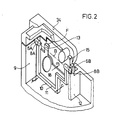
- FIG. 2 shows a locking device according to the present invention.
- the leg spring 37 has been omitted for reasons of clarity.
- the swivel plate 10 is formed with a frame 11 and has means at the foot with the locking device 7, formed from projections 41 and 42, which are visible in FIG. 4, for locking or for actuating the locking device from outside the cassette.
- At the upper end of the leg plate 10 are right and left cylindrical bearing elements 6A and 6B are provided as bearing devices 6.
- a common cylinder axis can also be used as a bearing device.
- the cylinder bearing elements 6A and 6B are parts of the bearing device 6, for which purpose bearing openings 8A and 8B in the outer wall 9 of the cassette and in the inner wall 12 are also to be counted.
- the bearing axis which is also the pivot axis of the pivot plate 10, is denoted by B.
- B The bearing axis, which is also the pivot axis of the pivot plate 10, is denoted by B.
- at least one support extension 13 is provided, which here has the shape of a nose with a cam 14 at the free end as a material thickening for spacing from the side outer wall 15.
- the contact point of the cam 14 on the inside of the side outer wall 15 is labeled "A".
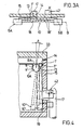
- FIG 3 the pivot plate 10 is shown with a uniform thickness e (without frame 11).
- the support extension 16 has a wedge shape with the largest material accumulation at the free end.
- Figure 3A shows a plan view of the pivot plate 10 in its design and arrangement from Figure 2.
- the drawn bending lines 18 ' show the elastic part 18 during the force application by means of the force K on the actuating projection 42 and the effect of the cam 14 on the support extension 13 the inside of the outer wall 15 at the contact point F.
- a-b should be 0 - 0.2 mm. This defines the angular position of the swivel plate 10 in the rest position and the degree of deflection in the operating position.
- FIG. 5 shows that contact points at S and T are present.
- contact point F there is also a contact point T on the lower edge 19 of the swivel plate 10, for example as shown in FIG. 4, where only one cam 14 and the lower edge 19 are used as contact parts themselves. If distance cams are used, the distance b to the contacting front end of the cam must be calculated and the dimensioning instructions above should be observed.
- Figure 4 shows the pivot plate 10 with the spacing cam 14 on the support extension 13 in the rest position 10 'and operating position 10' while in the rest position 10 '( Figure 2 and 3) the deflection angle ⁇ from the vertical is about 0.5-1.5 ° , which is also determined by the cam dimensions, the deflection angle ⁇ is approximately 10 ° in the operating position.
- ⁇ should be in the range of 5-20 °, which of course depends on the design and the actuation path W of the locking device, in particular the actuation projection 42 through the actuation pin 17.
- the materials mentioned must have a modulus of elasticity between 2500 N / mm2 and 3500 N / mm2, preferably of about 3000 N / mm2 because of the required flexible properties.
- the forces that were applied via the swivel plate 10 are predominantly bending forces.
- reaction forces of such swivel plates or similar locking or braking elements in the range from approx. 1 cN to 30 cN or even above can also be dimensioned, in particular if there are other dimensional and spatial conditions.
- the invention is described for video cassettes.
- the locking device can also be used advantageously for any type of cassette with an automatic unlocking device in the device.
- Cassettes of this type are also audio, data, film and disc cassettes.
Landscapes
- Sheets, Magazines, And Separation Thereof (AREA)
- Automatic Tape Cassette Changers (AREA)
- Casings For Electric Apparatus (AREA)
- Packaging Of Annular Or Rod-Shaped Articles, Wearing Apparel, Cassettes, Or The Like (AREA)
- Pivots And Pivotal Connections (AREA)
- Radiography Using Non-Light Waves (AREA)
Abstract
Description
- Die Erfindung betrifft eine Verriegelungseinrichtung für eine Kassette und eine Kassette damit, bestehend aus einem, um eine Lagerachse einer Lagereinrichtung verschwenkbaren Schwenkelement und einer daran unterhalb der Lagerachse angeordneten Riegeleinrichtung, wobei die Lagereinrichtung mit Gehäusewänden der Kassette zusammenwirkt und wobei das Schwenkelement wenigstens teilweise aus elastisch verformbarem Material besteht und wobei die Riegeleinrichtung zum Verschwenken betätigbar angeordnet ist.
- Es ist eine Verriegelungseinrichtung bekannt, bei dem eine schwenkbar gelagerte Verriegelungsplatte mittels einer daran befestigten, separaten Schwenkfeder gegen das Gehäuse der Kassette abgestützt ist, um eine Vorspannung in Verriegelungsposition zu erzeugen. Ein direkt verriegelnder Vorsprung an der Verriegelungsplatte steht in Verriegelungsposition mit einer Ausnehmung in einer Schwenkklappe der Kassette in Eingriff, und ein anderer Vorsprung an der Verriegelungsplatte wird zum Auslösen der Verriegelungsplatte von außerhalb des Gehäuses betätigt, und damit wird die Verriegelungsplatte gegen die Vorspannung verschwenkt und gibt die Schwenkklappe zum Aufschwenken und Öffnen der Kassette frei. (Vergleiche zu diesem Stand der Technik Figur 1.)
- Es ist eine weitere Verriegelungsklappe zum selben Zweck aus der US-PS 4 466 583 bzw. aus dem DE-GM 85 04 032 bekannt, wobei die Schwenkfeder des obigen Standes der Technik durch eine integrierte, angespritzte Kunststoffschwenkfeder ersetzt ist. Auch diese Ausführung einer integrierten Kunststoff-Feder ist nachteilig wegen der komplizierten und aufwendigen Fertigung, bei der aufwendige Werkzeuge notwendig sind, und durch die hervorstehenden Kunststoff-Federn, die die Weiterverarbeitung und Konfektionierung (Zusammenbau) der Kassetten durch Verhaken behindern.
- Die Erfindung hat sich daher die Aufgabe gestellt, die Nachteile der bekannten Verriegelungseinrichtungen und Kassetten damit auszuschalten, deren Herstellung wirtschaftlicher zu machen und deren Lebensdauer zu verlängern.
- Die Aufgabe wird mit einer Verriegelungseinrichtung für eine Kassette, bestehend aus einem, um eine Lagerachse einer Lagereinrichtung verschwenkbares Schwenkelement und einer daraus unterhalb der Lagerachse angeordneten Riegeleinrichtung, wobei die Lagereinrichtung mit Gehäusewänden der Kassette zusammenwirkt und wobei das Schwenkelement wenigstens teil weise aus elastisch verformbaren Material besteht und wobei die Riegeleinrichtung betätigbar angeordnet ist, dadurch gelöst,
daß das Schwenkelement oberhalb der Lagerachse einen Stützfortsatz aufweist und
daß das Schwenkelement mit dem Stützfortsatz und/oder einem Teil unterhalb der Lagerachse in Ruhelage mit der Innenseite der Außenwandung im wesentlichen spannungsfrei in Kontakt steht,
wobei in Betriebslage bei Betätigung der Riegeleinrichtung das Schwenkelement verschwenkt und dabei in einen Spannungseinstand überführt wird, wobei der Stützfortsatz in Kontakt mit der Innenseite der Gehäuseaußenwandung steht und der untere Teil des Schwenkelements nicht in Kontakt mit der Gehäusewandung steht. - Damit wird erreicht, daß das Schwenkelement gerade ohne oder praktisch mit minimalem Spiel oder Andruck an der Gehäusewandung anliegt. Das Schwenkelement befindet sich in seiner Winkel-Ruhelage, in der die Riegeleinrichtung nicht betätigt ist, praktisch unbelastet und völlig spannungsfrei in der Kassette, die z.B. eine VHS-Videocassette sein kann. Von etwa 5 bis 10 Jahren mittlerer Lagerzeit oder Benutzungsdauer ist eine solche Kassette kaum mehr als 100 bis 200 Stunden im Betrieb, das heißt nur in diesem relativ kurzen Zeitraum ist das Schwenkelement an seinem Stütz fortsatz, der als Widerlager wirksam ist, belastet. Demgegenüber stehen die angespritzten dünnen Kunststoffedern des Standes der Technik während der gesamten Lebensdauer der Kassetten unter Last und werden dehalb auch bei sehr elastischen, dünnen thermoplastischem Kunststoffmaterial einmal erlahmen, d.h., daß sich die Federeigenschaften ändern, da das thermoplastische Fließen dieser Kunststoffmaterialien last- und zeitdauerabhängig ist.
- Überraschend hat sich bei der Verriegelungseinrichtung der vorliegenden Erfindung gezeigt, daß durch die Anordnung des Stützfortsatzes direkt oberhalb der Lagerachse die innere Elastizität des Schwenkelements zwischen den Lagerpunkten der Lagereinrichtung zur Aufbringung einer Federkraft im Schwenkbereich des Schwenkelements, also bei und nach dessen Betätigung ausreicht, um in dessen Ruhelage die Verriegelungsfunktion aufrechtzuerhalten und in Betätigungslage die notwendige Vorspannung bzw. Federkraft aufzubringen.
- Praktisch ist jede Kontaktstelle zwischen dem Schwenkelement und der Gehäusewandung im Abstand von der Lagerachse vorgesehen. Zweckmäßig kann der wenigstens eine Stützfortsatz im wesentlichen in der Mitte zwischen den Lagerkörpern der Lagereinrichtung angeordnet sein. Dadurch ist ein nachträglicher Einbau in bereits vorhandene VHS-Cassetten möglich und außerdem ist ein im wesentlichen symmetrischer Kraftangriff gewährleistet.
- In praktischer Ausführung sind die Abstände der Kontaktstellen des Stützfortsatzes und des unteren Teils der Schwenkplatte von der Lagerachse etwa im Verhältnis von 1:12 bis 1:6 auszulegen, wodurch bei üblichen Maße der Schwenkplatte und bekannten thermoplastischen Materialien Kräfte in den gewünschten Größen erreichbar sind. Praktisch kann der Stützfortsatz am freien Ende gegenüber der Gehäuseaußenwandung mit einer Materialverdickung ausgebildet sein, wodurch eine Winkellage der Schwenkplatte erhalten wird.
- In Ruhelage der Schwenkplatte kann der Winkel zwischen derselben und der Gehäuseaußenwandung im Bereich von ca. 0,5° bis ca. 1,5° liegen. In zweckmäßiger Ausführung ist das Schwenkelement als Schwenkplatte ausgebildet. In weiterer praktischer Ausführung kann die Schwenkplatte mit einer rahmenartigen Verstärkung ausgebildet sein, die bis zu den Lagerkörpern der Lagereinrichtung reicht, und die Schwenkplatte kann zwischen den Lagerkörpern unter Einbezug des Stützfortsatzes mit gegenüber der Rahmenverstärkung verminderter Dicke und dadurch flexible ausgebildet sein.
- Eine Kassette, insbesondere Videokassette mit einer Verriegelungsvorrichtung für eine Kassettenklappe, kann die Merkmale der Patentansprüche für eine Verriegelungsvorrichtung vorteilhaft aufweisen.
- Insbesondere ist es dabei praktisch, daß das Schenkelement als Schwenkplatte ausgebildet ist.
- Es wird auch für eine praktische Dimensionierung als wichtig angesehen, daß die erste Kontaktstelle zwischen den Stützfortsatz des Schwenkelements und der Gehäusewandung (15) der Kassette und die zweite Kontaktstelle zwischen dem unteren Teil des Schwenkelements und der Gehäusewandung Abstände von der Lagerachse im Größenverhältnis von 1 : 6 bis 1 : 12 besitzen.
- In praktischer Ausgestaltung sind Schwenkelement und Lagerung im Kassettengehäuse so auszulegen, daß in Ruhelage des Schwenkelements der Winkel zwischen dem Schwenkelement und der Außenwandung im Bereich von ca. 0,5° bis ca. 1,5° liegt.
- Die Erfindung wird anhand von in Zeichnungen dargestellten Auführungsbeispielen nachfolgend beschrieben.
- Es zeigen:
- Figur 1
Stand der Technik, teilweise herausgebrochen dargestellt, - Figur 2 dasselbe Vorder-Eckteil mit einer Verriegelungseinrichtung mit einer Schwenkplatte mit integrierter Feder
- Figur 3 eine zweite Ausführung in Schwenkplatte mit integrierter Feder
- Figur 3A eine Draufsicht auf die Schwenkplatte gemäß Fig. 3
- Figur 4 die Verriegelungseinrichtung der Figur 1 in Seitenansicht in Ruhelage und Betätigungslage der Schwenkplatte
- Figur 5 eine Ausschnittsvergrößerung aus Figur 4, teilweise im Schnitt
- Figur 1 zeigt einen vorderen Eckteil 30 einer VHS-Cassette, bestehend aus oberen und unteren Gehäuseteilen 31, 32, die geeignet miteinander verbunden sind. Zum Schutz des nicht dargestellten Bandes vor Beschädigung dient eine Schwenkklappe 33 mit Seitenwänden 34, an deren Innenseiten Stifte 35 angespritzt sind, um die die Schwenkklappe verschwenkbar ist. Im unteren Gehäuseteil 31 ist eine schwenkbare Verriegelungsplatte 36 vorgesehen, welche mittels eines Vorsprungs 41, der in eine nicht dargestellte Ausnehmung in der Klappen-Seitenwand 34 eingreift, das Verriegeln durch die Verriegelungsplatte 36 bewerkstelligt. Die Schwenkplatte 33 mit Seitenwänden 34 ist gegenüber den Gehäuseteilen 31, 32 in Schließstellung vorgespannt mittels einer auf einem Zapfen 35 vorgesehenen Schwenkfeder 37, deren Schenkel 38 an der Unterseite der Schwenkklappe 33 angreift. Die Verriegelungsplatte 36 ist über eine weitere Schwenkfeder 39, die auf einem Lagerzapfen 40 der Verriegelungsplatte 36 angeordnet ist und deren Schenkel sich gegen eine Rippe des Gehäusebodenteils 31 abstützt, in ihrer Verriegelungsstellung vorgespannt. An der Verriegelungsplatte 36 ist auch ein größerer Betätigungsvorsprung 42 vorgesehen, der von außerhalb der Kassette betätigbar ist.
- In Figur 2 ist eine Verriegelungseinrichtung gemäß der vorliegenden Erfindung dargestellt. Die Schenkelfeder 37 ist aus Gründen der Übersichtlichkeit weggelassen worden. Die Schwenkplatte 10 ist mit einem Rahmen 11 ausgebildet und besitzt am Fuß mit der Riegeleinrichtung 7, gebildet aus Vorsprüngen 41 und 42, die in Figur 4 sichtbar sind, Mittel zur Verriegelung bzw. zur Betätigung der Verriegelungseinrichtung von außerhalb der Kassette. Am oberen Ende der Schenkplatte 10 sind rechts und links zylindrische Lagerelemente 6A und 6B als Lagereinrichtungen 6 vorgesehen. Es kann auch eine gemeinsame Zylinderachse als Lagereinrichtung verwendet werden. Die Zylinder-Lagerelemente 6A und 6B sind Teile der Lagereinrichtung 6, wozu noch Lageröffnungen 8A und 8B in der Kassettenaußenwand 9 bzw. in der Innenwand 12 gerechnet werden. Die Lagerachse, die gleichzeitig die Schwenkachse der Schwenkplatte 10 ist, ist mit B bezeichnet. Etwa in der Mitte zwischen den Lagerelementen 6A und 6B ist wenigstens ein Stützfortsatz 13 vorgesehen, der hier die Form einer Nase besitzt mit einer Nocke 14 am freien Ende als Materialverdickung zur Abstandshaltung gegenüber der Seitenaußenwandung 15. Die Kontaktstelle der Nocke 14 an der Innenseite der Seitenaußenwandung 15 ist mit "A" bezeichnet.
- In Figur 3 ist die Schwenkplatte 10 mit einheitlicher Dicke e (ohne Rahmen 11) dargestellt. Der Stützfortsatz 16 besitzt hier Keilform mit der größten Materialanhäufung am freien Ende. Figur 3A zeigt eine Draufsicht auf die Schwenkplatte 10 in ihrer Ausführung und Anordnung aus Figur 2. Die eingezeichneten Biegelinien 18′ zeigen den elastischen Teil 18 während des Kraftangriffs mittels der Kraft K am Betätigungsvorsprung 42 und die Wirkung der Anlage des Nockens 14 am Stützfortsatz 13 an der Innenseite der Außenwandung 15 an der Kontaktstelle F.
- Wie am deutlichsten aus Figur 5 hervorgeht ist es notwendig, die Berührungsstelle S des Lagerzylinderelements 6A, 6B in einem Abstand b von der der Außenwandung 9 zugewandten Seite der Schwenkplatte 10 vorzusehen, der sich zum Abstand a der Außenwandung selbst so verhält, daß a gleich oder geringfügig größer als b ist. In der Praxis soll a-b ∼ 0 - 0,2 mm betragen. Damit ist die Winkellage der Schwenkplatte 10 in Ruhelage und das Maß der Auslenkung in Betriebslage definiert.
- Es ist ferner notwendig, das seitliche Spiel c des Zylinderkörpers 6A, 6B in den Lageröffnungen 8A und 8B so zu dimensionieren, daß c - d ≧ 2 mm beträgt, wobei d der Zylinderdurchmesser ist. Damit kann sichergestellt werden, daß bei üblichen Toleranzen und normaler Flexibilität der Schwenkplatte 10 kein Verklemmen der Lagereinrichtung 6 auftritt.
- In Figur 5 ist dargestellt, daß Kontaktstellen an S und T vorhanden sind. Daneben ist es jedoch auch möglich, daß außer der Kontaktstelle F auch eine Kontaktstelle T an der Unterkante 19 der Schwenkplatte 10 vorhanden ist, z.B. wie in Figur 4 gezeigt, wo nur ein Nocken 14 und die Unterkante 19 als Kontaktteile selbst benutzt werden. Im Falle der Verwendung von Abstandsnocken ist der Abstand b bis zum kontaktierenden Vorderende der Nocke zu rechnen und obige Dimensionierungsvorschrift sollte gewahrt sein.
- Figur 4 zeigt die Schwenkplatte 10 mit dem Abstandsnocken 14 am Stützfortsatz 13 in Ruhelage 10′ und Betriebslage 10˝ während in der Ruhelage 10′ (Figur 2 u. 3) der Auslenkungswinkel α aus der Vertikalen etwa 0,5 - 1,5° beträgt, was auch durch die Nockenmaße bestimmt wird, beträgt in Betriebslage der Auslenkunkswinkel ß ca. 10°. Generell dürfte β im Bereich von 5 - 20° liegen, was natürlich von der Ausbildung und dem Betätigungsweg W der Riegeleinrichtung, insbesondere des Betätigungsvorsprungs 42 durch den Betätigungszapfen 17 abhängig ist.
- In der um den Winkel ß von z.B. 10° ausgelenkten Stellung 10˝ der Schwenkplatte 10 hat sich die Lage des Zapfens 6A geringfügig geändert (Versatz der Kontaktstellen S'nach S˝) und folglich hat sich auch die Kontaktstelle des Nockens 14 von T nach T′ verschoben. In dieser Lage 10˝ der Schwenkplatte 10 kommt ihre volle Elastizität und Flexibilität zur Wirkung, die in der Ausführung der Figur 2 durch den Bereich verminderter Dicke "m", 18 zwischen Rahmen 11 und Lagern 6A, 6B und durch den Stützfortsatz 13 bestimmt sind. Die Dicke des Rahmenteils 11 ist mit "r" bezeichnet. Beim VHS-System ist die Auslenkkraft als kleiner 15 pond15 cN festgelegt. Die in Figuren 3 und 3a dargestellte Ausführung benötigt zur Betätigung eine relativ kleine Auslenkkraft K ∼ 8-12 cN bei einem der folgenden Materialien: Polyoxymethylen (POM), Polystyrol (PS), Polypropylen (PP) oder ABS und bei POM bei einer Schwenkplattendicke von e = 1-2 mm. Die genannten Werkstoffe müssen dafür wegen der erforderlichen flexiblen Eigenschaften einen Elastizitätsmodul zwischen 2500 N/mm² und 3500 N/mm², vorzugsweise von etwa 3000 N/mm² aufweisen. Die Kräfte, die über die Schwenkplatte 10 aufgebracht wurden, sind vorwiegend Biegekräfte. Selbstverständlich können auch Reaktionskräfte von solchen Schwenkplatten oder ähnlichen Verriegelungs- oder Bremselementen im Bereich von ca. 1 cN bis 30 cN oder auch darüber dimensioniert werden, insbesondere, wenn andere Abmessungs- und Raumverhältnisse gegeben sind.

- Die Erfindung ist für Videokassetten beschrieben. Jedoch ist die Verriegelungseinrichtung für jede Art von Kassetten mit automatischer Entriegelungseinrichtung im Gerät ebenso vorteilhaft einsetzbar. Kassetten dieser Art sind auch Audio-, Daten-, Film- und Plattenkassetten.
Claims (12)
Priority Applications (1)
| Application Number | Priority Date | Filing Date | Title |
|---|---|---|---|
| AT88119550T ATE81226T1 (de) | 1987-12-03 | 1988-11-24 | Verriegelungseinrichtung fuer eine kassette und eine kassette damit. |
Applications Claiming Priority (2)
| Application Number | Priority Date | Filing Date | Title |
|---|---|---|---|
| DE8715990U | 1987-12-03 | ||
| DE8715990U DE8715990U1 (de) | 1987-12-03 | 1987-12-03 | Verriegelungseinrichtung für eine Kassette |
Publications (3)
| Publication Number | Publication Date |
|---|---|
| EP0318828A2 true EP0318828A2 (de) | 1989-06-07 |
| EP0318828A3 EP0318828A3 (en) | 1990-03-14 |
| EP0318828B1 EP0318828B1 (de) | 1992-09-30 |
Family
ID=6814719
Family Applications (1)
| Application Number | Title | Priority Date | Filing Date |
|---|---|---|---|
| EP88119550A Expired - Lifetime EP0318828B1 (de) | 1987-12-03 | 1988-11-24 | Verriegelungseinrichtung für eine Kassette und eine Kassette damit |
Country Status (9)
| Country | Link |
|---|---|
| US (1) | US5002239A (de) |
| EP (1) | EP0318828B1 (de) |
| JP (1) | JP2595337B2 (de) |
| KR (1) | KR890010890A (de) |
| CN (1) | CN1011642B (de) |
| AT (1) | ATE81226T1 (de) |
| DE (2) | DE8715990U1 (de) |
| HK (1) | HK31693A (de) |
| SG (1) | SG3293G (de) |
Cited By (1)
| Publication number | Priority date | Publication date | Assignee | Title |
|---|---|---|---|---|
| FR2670941A1 (fr) * | 1990-10-17 | 1992-06-26 | Shape Inc | Cassette de bande a ressort unique de rappel. |
Families Citing this family (4)
| Publication number | Priority date | Publication date | Assignee | Title |
|---|---|---|---|---|
| DE8715990U1 (de) * | 1987-12-03 | 1988-02-18 | Basf Ag, 6700 Ludwigshafen | Verriegelungseinrichtung für eine Kassette |
| JPH0544942Y2 (de) * | 1988-04-20 | 1993-11-16 | ||
| KR910008178Y1 (ko) * | 1988-08-18 | 1991-10-12 | 주식회사 에스 케이 씨 | 비디오 카세트의 커버 잠금장치 |
| JPH0745038A (ja) * | 1993-07-30 | 1995-02-14 | Tdk Corp | テープカセット |
Family Cites Families (10)
| Publication number | Priority date | Publication date | Assignee | Title |
|---|---|---|---|---|
| JPS593759A (ja) * | 1982-06-30 | 1984-01-10 | Hitachi Ltd | 磁気テ−プカ−トリツジの蓋ロツク機構 |
| US4466583A (en) * | 1982-08-12 | 1984-08-21 | T/B & H Home Video | Cassette door latch |
| NL8203219A (nl) * | 1982-08-17 | 1984-03-16 | Philips Nv | Magneetbandcassete. |
| US4608616A (en) * | 1982-12-08 | 1986-08-26 | Victor Company Of Japan, Ltd. | Tape cassette having a lock mechanism for locking a tape protecting lid |
| US4475700A (en) * | 1983-05-09 | 1984-10-09 | Shape Inc. | Tape cassette dust door latch spring assembly |
| DE3504965A1 (de) * | 1985-02-13 | 1986-08-14 | Agfa-Gevaert Ag, 5090 Leverkusen | Frontklappenverriegelung von magnetbandkassetten insbesondere videobandkassetten |
| DE8504032U1 (de) * | 1985-02-13 | 1985-05-09 | Agfa-Gevaert Ag, 5090 Leverkusen | Frontklappenverriegelung von magnetbandkassetten insbesondere videobandkassetten |
| KR900009622Y1 (ko) * | 1987-09-29 | 1990-10-15 | 주식회사 에스케이씨 | 비디오 테이프 카세트용 록커 |
| DE8713865U1 (de) * | 1987-10-15 | 1987-12-17 | Basf Ag, 6700 Ludwigshafen | Verriegelungselement für eine Kassette |
| DE8715990U1 (de) * | 1987-12-03 | 1988-02-18 | Basf Ag, 6700 Ludwigshafen | Verriegelungseinrichtung für eine Kassette |
-
1987
- 1987-12-03 DE DE8715990U patent/DE8715990U1/de not_active Expired
-
1988
- 1988-11-24 EP EP88119550A patent/EP0318828B1/de not_active Expired - Lifetime
- 1988-11-24 AT AT88119550T patent/ATE81226T1/de not_active IP Right Cessation
- 1988-11-24 DE DE8888119550T patent/DE3875084D1/de not_active Expired - Lifetime
- 1988-12-02 JP JP63304271A patent/JP2595337B2/ja not_active Expired - Fee Related
- 1988-12-02 US US07/279,020 patent/US5002239A/en not_active Expired - Lifetime
- 1988-12-03 CN CN88109210A patent/CN1011642B/zh not_active Expired
- 1988-12-03 KR KR1019880016144A patent/KR890010890A/ko not_active Withdrawn
-
1993
- 1993-01-07 SG SG32/93A patent/SG3293G/en unknown
- 1993-04-01 HK HK316/93A patent/HK31693A/xx unknown
Cited By (2)
| Publication number | Priority date | Publication date | Assignee | Title |
|---|---|---|---|---|
| FR2670941A1 (fr) * | 1990-10-17 | 1992-06-26 | Shape Inc | Cassette de bande a ressort unique de rappel. |
| ES2048063A2 (es) * | 1990-10-17 | 1994-03-01 | Shape Inc | "cassette de video cinta con disposicion combinada de puerta antipolvo y muelle de bloqueo para dicha puerta". |
Also Published As
| Publication number | Publication date |
|---|---|
| DE3875084D1 (de) | 1992-11-05 |
| CN1034631A (zh) | 1989-08-09 |
| SG3293G (en) | 1993-03-12 |
| JP2595337B2 (ja) | 1997-04-02 |
| JPH01282785A (ja) | 1989-11-14 |
| CN1011642B (zh) | 1991-02-13 |
| ATE81226T1 (de) | 1992-10-15 |
| HK31693A (en) | 1993-04-08 |
| DE8715990U1 (de) | 1988-02-18 |
| EP0318828A3 (en) | 1990-03-14 |
| US5002239A (en) | 1991-03-26 |
| EP0318828B1 (de) | 1992-09-30 |
| KR890010890A (ko) | 1989-08-11 |
Similar Documents
| Publication | Publication Date | Title |
|---|---|---|
| DE69420415T2 (de) | Ringordnermechanismus | |
| AT401665B (de) | Scharnier, insbesondere für türen | |
| DE8702289U1 (de) | Aufbewahrungsbehälter, im wesentlichen von Quaderform, für insbesondere flache Gegenstände | |
| EP0323437A2 (de) | Behälter für flache Audio- oder Videoaufzeichnungsträger | |
| DE19728641A1 (de) | Positionsscharnier für Türen | |
| DE10325099A1 (de) | Seitenverriegelungsvorrichtung | |
| DE102021215017A1 (de) | Steckverbinder, der eine positionsabweichung beim einführen eines gegenanschlusses zulassen kann | |
| DE2841527A1 (de) | Stiftloses scharnier | |
| DE69027340T2 (de) | Behälter für optische platten mit struktur zur Vermeidung eines Versatzes einer Feder. | |
| EP0318828B1 (de) | Verriegelungseinrichtung für eine Kassette und eine Kassette damit | |
| EP0630019A1 (de) | Kassette zur Aufnahme mindestens einer Datenträgerplatte | |
| WO2000060199A1 (de) | Verstellvorrichtung für ausstellfenster | |
| EP0311920B1 (de) | Kassette mit Verriegelungselement | |
| EP0727805B1 (de) | Kontakthebelbaugruppe für einen Niederspannungs-Leistungsschalter | |
| DE2936860A1 (de) | Fuehrungsscheibe fuer magnetbandkassette | |
| DE69711389T2 (de) | Torsionsvorgespannte einschnappbare verriegelungsvorrichtung | |
| DE3784145T2 (de) | Bandkassette. | |
| DE69819380T2 (de) | Federscharnier | |
| EP1298692B1 (de) | Schaltkontaktanordnung eines Niederspannungs-Leistungsschalters | |
| EP0230259B1 (de) | Behälter von Quaderform für Gegenstände | |
| EP0159494A1 (de) | Schliesszylinder und Flachschlüssel für diesen | |
| EP0191387A1 (de) | Frontklappenverriegelung von Magnetbandkassetten insbesondere Videobandkassetten | |
| DE69023069T2 (de) | Integrierte Rastfeder für einen Staubschutzdeckel einer Videokassette. | |
| DE4226273C2 (de) | Rollbandmaß | |
| EP1014374B1 (de) | Verschliessbare Aufbewahrungskassette für eine kreisförmige Informationsplatte, insbesondere eine digitale Informationen speichernde Compact Disc |
Legal Events
| Date | Code | Title | Description |
|---|---|---|---|
| PUAI | Public reference made under article 153(3) epc to a published international application that has entered the european phase |
Free format text: ORIGINAL CODE: 0009012 |
|
| AK | Designated contracting states |
Kind code of ref document: A2 Designated state(s): AT DE FR GB IT NL SE |
|
| PUAL | Search report despatched |
Free format text: ORIGINAL CODE: 0009013 |
|
| AK | Designated contracting states |
Kind code of ref document: A3 Designated state(s): AT DE FR GB IT NL SE |
|
| 17P | Request for examination filed |
Effective date: 19900328 |
|
| 17Q | First examination report despatched |
Effective date: 19910918 |
|
| GRAA | (expected) grant |
Free format text: ORIGINAL CODE: 0009210 |
|
| AK | Designated contracting states |
Kind code of ref document: B1 Designated state(s): AT DE FR GB IT NL SE |
|
| REF | Corresponds to: |
Ref document number: 81226 Country of ref document: AT Date of ref document: 19921015 Kind code of ref document: T |
|
| ITF | It: translation for a ep patent filed | ||
| REF | Corresponds to: |
Ref document number: 3875084 Country of ref document: DE Date of ref document: 19921105 |
|
| GBT | Gb: translation of ep patent filed (gb section 77(6)(a)/1977) | ||
| ET | Fr: translation filed | ||
| PLBE | No opposition filed within time limit |
Free format text: ORIGINAL CODE: 0009261 |
|
| STAA | Information on the status of an ep patent application or granted ep patent |
Free format text: STATUS: NO OPPOSITION FILED WITHIN TIME LIMIT |
|
| 26N | No opposition filed | ||
| PGFP | Annual fee paid to national office [announced via postgrant information from national office to epo] |
Ref country code: FR Payment date: 19931018 Year of fee payment: 6 |
|
| PGFP | Annual fee paid to national office [announced via postgrant information from national office to epo] |
Ref country code: SE Payment date: 19931019 Year of fee payment: 6 |
|
| PGFP | Annual fee paid to national office [announced via postgrant information from national office to epo] |
Ref country code: AT Payment date: 19931028 Year of fee payment: 6 |
|
| PGFP | Annual fee paid to national office [announced via postgrant information from national office to epo] |
Ref country code: GB Payment date: 19931115 Year of fee payment: 6 |
|
| PGFP | Annual fee paid to national office [announced via postgrant information from national office to epo] |
Ref country code: NL Payment date: 19931130 Year of fee payment: 6 |
|
| PG25 | Lapsed in a contracting state [announced via postgrant information from national office to epo] |
Ref country code: GB Effective date: 19941124 Ref country code: AT Effective date: 19941124 |
|
| PG25 | Lapsed in a contracting state [announced via postgrant information from national office to epo] |
Ref country code: SE Effective date: 19941125 |
|
| EAL | Se: european patent in force in sweden |
Ref document number: 88119550.7 |
|
| PG25 | Lapsed in a contracting state [announced via postgrant information from national office to epo] |
Ref country code: NL Effective date: 19950601 |
|
| NLV4 | Nl: lapsed or anulled due to non-payment of the annual fee | ||
| GBPC | Gb: european patent ceased through non-payment of renewal fee |
Effective date: 19941124 |
|
| PG25 | Lapsed in a contracting state [announced via postgrant information from national office to epo] |
Ref country code: FR Effective date: 19950731 |
|
| EUG | Se: european patent has lapsed |
Ref document number: 88119550.7 |
|
| REG | Reference to a national code |
Ref country code: FR Ref legal event code: ST |
|
| PGFP | Annual fee paid to national office [announced via postgrant information from national office to epo] |
Ref country code: DE Payment date: 20011102 Year of fee payment: 14 |
|
| PG25 | Lapsed in a contracting state [announced via postgrant information from national office to epo] |
Ref country code: DE Free format text: LAPSE BECAUSE OF NON-PAYMENT OF DUE FEES Effective date: 20030603 |
|
| PG25 | Lapsed in a contracting state [announced via postgrant information from national office to epo] |
Ref country code: IT Free format text: LAPSE BECAUSE OF NON-PAYMENT OF DUE FEES;WARNING: LAPSES OF ITALIAN PATENTS WITH EFFECTIVE DATE BEFORE 2007 MAY HAVE OCCURRED AT ANY TIME BEFORE 2007. THE CORRECT EFFECTIVE DATE MAY BE DIFFERENT FROM THE ONE RECORDED. Effective date: 20051124 |