EP0318884A1 - Procédé et dispositif de contrôle d'une chambre de combustion à lit fluidisé sous pression - Google Patents
Procédé et dispositif de contrôle d'une chambre de combustion à lit fluidisé sous pression Download PDFInfo
- Publication number
- EP0318884A1 EP0318884A1 EP88119767A EP88119767A EP0318884A1 EP 0318884 A1 EP0318884 A1 EP 0318884A1 EP 88119767 A EP88119767 A EP 88119767A EP 88119767 A EP88119767 A EP 88119767A EP 0318884 A1 EP0318884 A1 EP 0318884A1
- Authority
- EP
- European Patent Office
- Prior art keywords
- valve
- conduit
- bed
- turbine
- vessel
- Prior art date
- Legal status (The legal status is an assumption and is not a legal conclusion. Google has not performed a legal analysis and makes no representation as to the accuracy of the status listed.)
- Granted
Links
- 238000000034 method Methods 0.000 title claims abstract description 18
- 208000016791 bilateral striopallidodentate calcinosis Diseases 0.000 title claims abstract 9
- 239000007789 gas Substances 0.000 claims abstract description 58
- 238000002347 injection Methods 0.000 claims abstract description 20
- 239000007924 injection Substances 0.000 claims abstract description 20
- 239000000567 combustion gas Substances 0.000 claims abstract description 19
- 238000002485 combustion reaction Methods 0.000 claims abstract description 13
- 238000011144 upstream manufacturing Methods 0.000 claims abstract 4
- 239000011236 particulate material Substances 0.000 claims abstract 2
- 239000002826 coolant Substances 0.000 claims description 17
- XLYOFNOQVPJJNP-UHFFFAOYSA-N water Substances O XLYOFNOQVPJJNP-UHFFFAOYSA-N 0.000 claims description 16
- 229920000136 polysorbate Polymers 0.000 claims description 2
- 239000003380 propellant Substances 0.000 claims 2
- 239000002253 acid Substances 0.000 claims 1
- 239000000498 cooling water Substances 0.000 abstract description 9
- 238000001816 cooling Methods 0.000 abstract description 3
- 235000019628 coolness Nutrition 0.000 abstract 1
- 239000000446 fuel Substances 0.000 description 10
- JTJMJGYZQZDUJJ-UHFFFAOYSA-N phencyclidine Chemical class C1CCCCN1C1(C=2C=CC=CC=2)CCCCC1 JTJMJGYZQZDUJJ-UHFFFAOYSA-N 0.000 description 8
- 239000000463 material Substances 0.000 description 6
- IJGRMHOSHXDMSA-UHFFFAOYSA-N Atomic nitrogen Chemical compound N#N IJGRMHOSHXDMSA-UHFFFAOYSA-N 0.000 description 5
- UGFAIRIUMAVXCW-UHFFFAOYSA-N Carbon monoxide Chemical compound [O+]#[C-] UGFAIRIUMAVXCW-UHFFFAOYSA-N 0.000 description 3
- 229910002091 carbon monoxide Inorganic materials 0.000 description 3
- 238000013016 damping Methods 0.000 description 3
- 239000000428 dust Substances 0.000 description 3
- 238000004880 explosion Methods 0.000 description 3
- 238000005245 sintering Methods 0.000 description 3
- 208000036366 Sensation of pressure Diseases 0.000 description 2
- 230000015572 biosynthetic process Effects 0.000 description 2
- 238000007664 blowing Methods 0.000 description 2
- 238000004140 cleaning Methods 0.000 description 2
- 238000011161 development Methods 0.000 description 2
- 230000018109 developmental process Effects 0.000 description 2
- 238000005243 fluidization Methods 0.000 description 2
- 239000007788 liquid Substances 0.000 description 2
- 229910052757 nitrogen Inorganic materials 0.000 description 2
- 238000007789 sealing Methods 0.000 description 2
- GRYSXUXXBDSYRT-WOUKDFQISA-N (2r,3r,4r,5r)-2-(hydroxymethyl)-4-methoxy-5-[6-(methylamino)purin-9-yl]oxolan-3-ol Chemical compound C1=NC=2C(NC)=NC=NC=2N1[C@@H]1O[C@H](CO)[C@@H](O)[C@H]1OC GRYSXUXXBDSYRT-WOUKDFQISA-N 0.000 description 1
- QVGXLLKOCUKJST-UHFFFAOYSA-N atomic oxygen Chemical compound [O] QVGXLLKOCUKJST-UHFFFAOYSA-N 0.000 description 1
- 239000003245 coal Substances 0.000 description 1
- 230000007423 decrease Effects 0.000 description 1
- 230000001627 detrimental effect Effects 0.000 description 1
- 229910001873 dinitrogen Inorganic materials 0.000 description 1
- 238000001704 evaporation Methods 0.000 description 1
- 230000008020 evaporation Effects 0.000 description 1
- 239000011261 inert gas Substances 0.000 description 1
- 238000002156 mixing Methods 0.000 description 1
- 239000001301 oxygen Substances 0.000 description 1
- 229910052760 oxygen Inorganic materials 0.000 description 1
- 238000005086 pumping Methods 0.000 description 1
- 238000011946 reduction process Methods 0.000 description 1
- 238000000926 separation method Methods 0.000 description 1
- 238000003860 storage Methods 0.000 description 1
- 239000002912 waste gas Substances 0.000 description 1
Images

Classifications
-
- F—MECHANICAL ENGINEERING; LIGHTING; HEATING; WEAPONS; BLASTING
- F02—COMBUSTION ENGINES; HOT-GAS OR COMBUSTION-PRODUCT ENGINE PLANTS
- F02C—GAS-TURBINE PLANTS; AIR INTAKES FOR JET-PROPULSION PLANTS; CONTROLLING FUEL SUPPLY IN AIR-BREATHING JET-PROPULSION PLANTS
- F02C3/00—Gas-turbine plants characterised by the use of combustion products as the working fluid
- F02C3/20—Gas-turbine plants characterised by the use of combustion products as the working fluid using a special fuel, oxidant, or dilution fluid to generate the combustion products
- F02C3/205—Gas-turbine plants characterised by the use of combustion products as the working fluid using a special fuel, oxidant, or dilution fluid to generate the combustion products in a fluidised-bed combustor
-
- F—MECHANICAL ENGINEERING; LIGHTING; HEATING; WEAPONS; BLASTING
- F02—COMBUSTION ENGINES; HOT-GAS OR COMBUSTION-PRODUCT ENGINE PLANTS
- F02C—GAS-TURBINE PLANTS; AIR INTAKES FOR JET-PROPULSION PLANTS; CONTROLLING FUEL SUPPLY IN AIR-BREATHING JET-PROPULSION PLANTS
- F02C9/00—Controlling gas-turbine plants; Controlling fuel supply in air- breathing jet-propulsion plants
- F02C9/16—Control of working fluid flow
- F02C9/18—Control of working fluid flow by bleeding, bypassing or acting on variable working fluid interconnections between turbines or compressors or their stages
-
- F—MECHANICAL ENGINEERING; LIGHTING; HEATING; WEAPONS; BLASTING
- F23—COMBUSTION APPARATUS; COMBUSTION PROCESSES
- F23C—METHODS OR APPARATUS FOR COMBUSTION USING FLUID FUEL OR SOLID FUEL SUSPENDED IN A CARRIER GAS OR AIR
- F23C10/00—Fluidised bed combustion apparatus
- F23C10/16—Fluidised bed combustion apparatus specially adapted for operation at superatmospheric pressures, e.g. by the arrangement of the combustion chamber and its auxiliary systems inside a pressure vessel
Definitions
- the invention relates to a method of controlling a Pressurized Fluidized Bed Combustion (PFBC) power plant according to the introductory part of claim 1, in the event of an operational disturbance affecting the gas turbine unit.
- PFBC Pressurized Fluidized Bed Combustion
- the invention also relates to a PFBC power plant with equipment for such control.
- the gas turbine unit of the plant cannot rapidly regain normal operating conditions, for example by re-synchronizing of the generator of a power turbine, the very large energy contents of the PFBC plant in the hot bed, in the surrounding pressure vessel and in unburnt fuel in the bed entails special and difficult problems to solve.
- the energy contents in the bed and in the unburnt fuel have to be removed in a unharming manner.
- shutting off the turbine the gas flow through the bed vessel and the turbine is reduced to a level determined by the unavoidable leakage flow through the valve in the hot gas conduit between the bed vessel and the turbine.
- the air supply to the bed becomes insufficient for fluidization of the bed and for complete combustion of the fuel present in the bed.
- Combustion of this gas downstream of the cut-off valve may entail an impermissibly high gas temperature for the gas turbine and that the energy contents may give an impermissibly high speed of turbines in the plant.
- a disadvantage with this method is that compressed combustion air is to a large extent consumed for cooling of the combustion gases which leave the bed vessel and do not pass through the bed. This may mean that the fuel in the bed is not completely burnt and that the bed material will not be cooled to the desired extent.
- the combustible gases may entail a risk of explosion.
- a high bed temperature after a blow-off may result in the bed material sintering.
- a certain leakage into the bed vessel may be tolerated.
- the method is not completely satisfactory.
- US-A-4 744 212 discloses a method of overcoming the problems by supplying an inert gas, suitably nitrogen, to the bed vessel when the turbine is being shut off. This interrupts the supply of oxygen to the bed and hence the combustion, thus preventing the formation of carbon monoxide and eliminating the risk of explosion.
- an inert gas suitably nitrogen
- the invention aims at a method to discharge the energy alive in the power plant, in case of a disturbance of the kind explained above, in a manner not suffering from the above-mentioned disadvantages of the known methods and without having other detrimental effects.
- the invention also aims to develop a plant able to function in accordance with the method according to the invention.
- a power plant for implementing the method according to the invention is characterized by the features of claim 7.
- the gas turbine of the plant or the gas turbine and the combustion air compressor is/are shut off in a known manner from the bed vessel or the pressure vessel, surrounding the bed vessel, by shutting off the valve in the hot gas conduit between the bed vessel and the turbine or the turbines and by shutting off the valve in the air conduit between the compressor and the pressure vessel.
- a short circuit valve is opened in a short-circuit conduit between the air conduit and the hot gas conduit, so that air from the compressor is passed directly to the turbine.
- a certain residual flow through the valve in the hot gas conduit is obtained owing to the fact that a complete sealing cannot be achieved in a valve which is subjected to hot gas at a temperature of 800-950°C.
- the remaining fuel in the bed must be burnt and the bed be cooled. Gas from the bed vessel is dumped to the atmosphere via a damping conduit extending directly from the bed vessel, or via a conduit extending from the hot gas conduit to the turbine the damping conduit being provided with a blow-off valve.
- the damping conduit is provided with an injection device for a coolant through which, when the combustion gases are dumped, coolant is injected in such an amount that the gases are efficiently cooled before they reach the blow-off valve.
- coolant is injected in such an amount that the gases are cooled to a temperature of 400°C.
- Water is a suitable coolant, but also other liquids, for example liquid nitrogen, may be used.
- Cooling water for injection into the blow-off or dump conduit is suitably stored in a container pressurized by gas.
- the container communicates with the injection device via a conduit with a valve which is operatable by means of an operating device connected to the control equipment of the power plant.
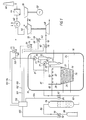
- 10 designates a pressure vessel.
- the pressure vessel accommodates a bed vessel 12 and a cleaning plant, symbolized by two series-connected cyclones 14 and 15.
- the cleaning plant comprises a number of parallel-connected groups of series-connected cyclones.
- the space 16 between the pressure vessel 10 and the bed vessel 12 contains compressed combustion air.
- the pressure may amount to 2 MPa or more.
- Combustion air is supplied to the bed vessel 12 via nozzles 18 at the bottom 20. This air fluidizes the bed 22 in the lower part of the bed vessel 12 and burns a fuel, usually coal, which is supplied to the bed 22 from a fuel storage (not shown) via the conduit 24.
- the bed 22 contains tubes 26 in which steam is generated and fed to a steam turbine (not shown) driving a generator.
- the combustion gases are collected in the freeboard 28 and are conducted in the conduits 30 and 31 to the cyclones 14 and 15, which represent a usually employed plurality of parallel- connected groups of series connected cyclones.
- From the cyclone 15 the hot gases are conducted via the conduit 32 to a high pressure turbine 34, from there via a conduit 36 to a low pressure turbine 38 and from there further via the conduit 40 to the economizer 42, the filter 44 and further, through the chimney 46, into the atmosphere.
- the high pressure turbine 34 drives the compressor 48. Via the conduit 50, the space 16 is supplied with compressed combustion air.
- the low-pressure turbine 38 drives a generator 52.
- the hot gas conduit 32 includes a cut-off valve 54 with an operating device 56.
- the conduit 50 from the compressor 48 is provided with a cut-off valve 58 with an operating device 60.
- a passage way for dumping combustion gases from the bed vessel 12 is provided by a conduit 68 extending from the hot gas conduit 32 between cyclone 15 and turbine 34 and opening out into the economizer 42.
- the conduit 68 is provided with at least one dump valve 72 with an operating device 74. For security reaverssons two such valves are usually connected in series.
- a device 70 with nozzles 71 for injection of cooling water is provided at the outlet side of cyclone 15 or in the dump conduit 68.
- Injection of cooling water into the freeboard 28 of the bed vessel 12 entails a long dwell time of injected water in the hot gases for evaporation and good mixing in the cyclones.
- the injection of cooling water in the injection device 70 can thereby be limited.
- a plant can be constructed with one or more of the water injection devices 70,70′ and 83 shown.
- the water injection devices 70,70′ and 83 are connected to a pressurized cooling water tank 78 via the conduit 80, the valve 82 with the operating device 84 and the conduits 81,81′ and 85.
- the water tank 78 communicates with a pressure gas source 88 via the conduit 86. Nitrogen gas is suitivelyably used.
- the conduit 86 comprises a valve 90 with an operating device 92.
- the operating devices 56,60,66,74,84,92 of the valves 54,58,64,72,82,90 are connected by conduits 100-105 to an operating unit 110, which forms part of the central control equipment for the plant.
- a temperature sensor 112 in the dump conduit 68 is connected to the operating unit 110 via the conduit 114.
- the dump conduit 68 is connected directly to the freeboard 28 of the bed vessel 12. Between the dump valve 72 and the economizer 42 there is a gas cleaner 76 for separation of dust.
- the fuel supply to the bed 22 is stopped and the valves 54 and 58 in the hot gas conduit 32 and in the air conduit 50, respectively, are shut off so that the turbines 34 and 38 and the compressor 48 are cut off from the bed vessel 12 and from the pressure vessel 10, respectively.
- the by-pass valve 64 in the short-circuit conduit 62 is opened so that the air from the compressor 48 flows directly into the turbine 34.
- the valve 72 is opened and the combustion gases from the bed vessel 12 are dumped.
- the valve 82 is at the same time opened, and cooling water is injected into the hot gas stream through nozzles 71,71′,87 in the water injection device 70,70′,83 in the embodiment shown in Figure 1.
- the water is evaporated and lowers the temperature of the gases before they reach the blow-off valve 72. Dust is separated in the cyclones 14,15 or in the cleaner 76.
- the gases are cooled in the economizer 42 to a temperature tolerable for the filter 44, whereupon the gases are led to the chimney 46.
- the gas temperature drops as the gas flow successively decreases.
- the flow of cooling water should be controlled.
- the water injection is suitably controlled by the valve 82 so that the temperature of the gases when they enter the economizer 42 is equal to or somewhat lower than the temperature of the waste gases from the turbine during normal operation, i.e. about 400°C. This results in the lowest temperature stress on the economizer 42 when blowing off the combustion gases from the bed vessel 12.
- the capacity in the dump conduit 68 is chosen such that a sufficient fluidization of the bed 22 is obtained.
- fuel remaining in the bed 22 is burnt.
- the air flowing through the bed 22 cools the bed material.
- the tubes 26, through which water and steam flow, contribute at the same time to the cooling of the bed material.
- the compressed combustion air in the space 16 has been consumed, the bed material has been cooled to such an extent that the risk of it sintering together is eliminated.
Landscapes
- Engineering & Computer Science (AREA)
- Combustion & Propulsion (AREA)
- Chemical & Material Sciences (AREA)
- General Engineering & Computer Science (AREA)
- Mechanical Engineering (AREA)
- Fluid Mechanics (AREA)
- Physics & Mathematics (AREA)
- Engine Equipment That Uses Special Cycles (AREA)
- Fluidized-Bed Combustion And Resonant Combustion (AREA)
- Control Of Turbines (AREA)
- Incineration Of Waste (AREA)
- Feeding And Controlling Fuel (AREA)
- Chairs Characterized By Structure (AREA)
- Control Of Fluid Pressure (AREA)
Priority Applications (1)
| Application Number | Priority Date | Filing Date | Title |
|---|---|---|---|
| AT88119767T ATE87068T1 (de) | 1987-12-02 | 1988-11-26 | Verfahren und vorrichtung zum regeln einer druck- wirbelbett-brennkammer in einer kraftwerksanlage. |
Applications Claiming Priority (2)
| Application Number | Priority Date | Filing Date | Title |
|---|---|---|---|
| SE8704823 | 1987-12-02 | ||
| SE8704823A SE464715B (sv) | 1987-12-02 | 1987-12-02 | Saett att reglera en pfbc-anlaeggning vid driftstoerning i gasturbinaggregat och en pfbc-anlaeggning med utrustning foer saadan reglering |
Publications (2)
| Publication Number | Publication Date |
|---|---|
| EP0318884A1 true EP0318884A1 (fr) | 1989-06-07 |
| EP0318884B1 EP0318884B1 (fr) | 1993-03-17 |
Family
ID=20370480
Family Applications (1)
| Application Number | Title | Priority Date | Filing Date |
|---|---|---|---|
| EP88119767A Expired - Lifetime EP0318884B1 (fr) | 1987-12-02 | 1988-11-26 | Procédé et dispositif de contrôle d'une chambre de combustion à lit fluidisé sous pression |
Country Status (11)
| Country | Link |
|---|---|
| US (1) | US5016435A (fr) |
| EP (1) | EP0318884B1 (fr) |
| JP (1) | JP2682681B2 (fr) |
| CN (1) | CN1016084B (fr) |
| AT (1) | ATE87068T1 (fr) |
| AU (1) | AU613119B2 (fr) |
| DE (1) | DE3879407T2 (fr) |
| DK (1) | DK166923B1 (fr) |
| ES (1) | ES2040313T3 (fr) |
| FI (1) | FI99045C (fr) |
| SE (1) | SE464715B (fr) |
Cited By (1)
| Publication number | Priority date | Publication date | Assignee | Title |
|---|---|---|---|---|
| US5309707A (en) * | 1993-03-12 | 1994-05-10 | Pyropower Corporation | Control methods and valve arrangement for start-up and shutdown of pressurized combustion and gasification systems integrated with a gas turbine |
Families Citing this family (7)
| Publication number | Priority date | Publication date | Assignee | Title |
|---|---|---|---|---|
| US5190451A (en) * | 1991-03-18 | 1993-03-02 | Combustion Power Company, Inc. | Emission control fluid bed reactor |
| US5236354A (en) * | 1991-03-18 | 1993-08-17 | Combustion Power Company, Inc. | Power plant with efficient emission control for obtaining high turbine inlet temperature |
| KR960700400A (ko) * | 1992-12-30 | 1996-01-20 | 아더 이. 퍼니어 2세 | 융화된 가스화 복합 싸이클 시스템(Control system for integrated gasification combined cycle system) |
| US5491967A (en) * | 1994-02-23 | 1996-02-20 | Foster Wheeler Energia Oy | Pressurized fluidized bed reactor and a method of operating the same |
| US9441887B2 (en) * | 2011-02-22 | 2016-09-13 | Ensyn Renewables, Inc. | Heat removal and recovery in biomass pyrolysis |
| US10041667B2 (en) | 2011-09-22 | 2018-08-07 | Ensyn Renewables, Inc. | Apparatuses for controlling heat for rapid thermal processing of carbonaceous material and methods for the same |
| JP5832944B2 (ja) * | 2012-03-26 | 2015-12-16 | 月島機械株式会社 | 加圧流動炉システムの非常停止方法 |
Citations (3)
| Publication number | Priority date | Publication date | Assignee | Title |
|---|---|---|---|---|
| US4315400A (en) * | 1980-02-08 | 1982-02-16 | Curtiss-Wright Corporation | Method of and apparatus for preheating pressurized fluidized bed combustor and clean-up subsystem of a gas turbine power plant |
| US4498286A (en) * | 1982-06-14 | 1985-02-12 | Stal-Laval Turbin Ab | Gas turbine plant with a fluidized bed combustion chamber |
| US4498285A (en) * | 1982-06-14 | 1985-02-12 | Stal-Laval Turbin Ab | Gas turbine plant with a fluidized bed combustion chamber |
Family Cites Families (5)
| Publication number | Priority date | Publication date | Assignee | Title |
|---|---|---|---|---|
| US3203175A (en) * | 1962-07-31 | 1965-08-31 | Michalicka Ladislav | System of operation of a steam-gas circuit or of a gas circuit for gas turbines comprising a combustion chamber for solid fuel |
| SE421945B (sv) * | 1978-09-12 | 1982-02-08 | Stal Laval Turbin Ab | Gasturbinanleggning |
| US4306411A (en) * | 1980-02-08 | 1981-12-22 | Curtiss-Wright Corporation | Compressor protective control system for a gas turbine power plant |
| EP0037858B1 (fr) * | 1980-04-16 | 1984-01-25 | BBC Aktiengesellschaft Brown, Boveri & Cie. | Centrale à vapeur avec générateur de vapeur à combustion sous pression et à lit fluidisé |
| SE458047B (sv) * | 1986-01-24 | 1989-02-20 | Asea Stal Ab | Saett att reglera en pfbc-anlaeggning vid driftstoerning i gasturbinaggregat samt en pfbc-anlaeggning med utrustning foer saadan reglering |
-
1987
- 1987-12-02 SE SE8704823A patent/SE464715B/sv not_active IP Right Cessation
-
1988
- 1988-11-26 EP EP88119767A patent/EP0318884B1/fr not_active Expired - Lifetime
- 1988-11-26 ES ES198888119767T patent/ES2040313T3/es not_active Expired - Lifetime
- 1988-11-26 AT AT88119767T patent/ATE87068T1/de not_active IP Right Cessation
- 1988-11-26 DE DE88119767T patent/DE3879407T2/de not_active Expired - Fee Related
- 1988-11-30 DK DK667788A patent/DK166923B1/da not_active IP Right Cessation
- 1988-11-30 CN CN88108204A patent/CN1016084B/zh not_active Expired
- 1988-11-30 AU AU26352/88A patent/AU613119B2/en not_active Ceased
- 1988-12-01 JP JP63305102A patent/JP2682681B2/ja not_active Expired - Lifetime
- 1988-12-01 FI FI885600A patent/FI99045C/fi not_active IP Right Cessation
-
1990
- 1990-09-28 US US07/598,823 patent/US5016435A/en not_active Expired - Lifetime
Patent Citations (3)
| Publication number | Priority date | Publication date | Assignee | Title |
|---|---|---|---|---|
| US4315400A (en) * | 1980-02-08 | 1982-02-16 | Curtiss-Wright Corporation | Method of and apparatus for preheating pressurized fluidized bed combustor and clean-up subsystem of a gas turbine power plant |
| US4498286A (en) * | 1982-06-14 | 1985-02-12 | Stal-Laval Turbin Ab | Gas turbine plant with a fluidized bed combustion chamber |
| US4498285A (en) * | 1982-06-14 | 1985-02-12 | Stal-Laval Turbin Ab | Gas turbine plant with a fluidized bed combustion chamber |
Cited By (1)
| Publication number | Priority date | Publication date | Assignee | Title |
|---|---|---|---|---|
| US5309707A (en) * | 1993-03-12 | 1994-05-10 | Pyropower Corporation | Control methods and valve arrangement for start-up and shutdown of pressurized combustion and gasification systems integrated with a gas turbine |
Also Published As
| Publication number | Publication date |
|---|---|
| SE8704823D0 (sv) | 1987-12-02 |
| DE3879407T2 (de) | 1993-10-07 |
| JPH01195928A (ja) | 1989-08-07 |
| DK667788A (da) | 1989-06-03 |
| DE3879407D1 (de) | 1993-04-22 |
| FI99045C (fi) | 1997-09-25 |
| DK667788D0 (da) | 1988-11-30 |
| FI99045B (fi) | 1997-06-13 |
| CN1016084B (zh) | 1992-04-01 |
| FI885600A7 (fi) | 1989-06-03 |
| US5016435A (en) | 1991-05-21 |
| FI885600A0 (fi) | 1988-12-01 |
| ES2040313T3 (es) | 1993-10-16 |
| DK166923B1 (da) | 1993-08-02 |
| AU613119B2 (en) | 1991-07-25 |
| JP2682681B2 (ja) | 1997-11-26 |
| EP0318884B1 (fr) | 1993-03-17 |
| CN1034409A (zh) | 1989-08-02 |
| SE464715B (sv) | 1991-06-03 |
| ATE87068T1 (de) | 1993-04-15 |
| AU2635288A (en) | 1989-06-08 |
| SE8704823L (sv) | 1989-06-03 |
Similar Documents
| Publication | Publication Date | Title |
|---|---|---|
| US4584949A (en) | Method of igniting a combustion chamber with a fluidized bed and a power plant for utilizing the method | |
| US5634329A (en) | Method of maintaining a nominal working temperature of flue gases in a PFBC power plant | |
| EP0619455B1 (fr) | Chaudière à lit fluidisé sous pression à circulation interne | |
| US4896497A (en) | PFBC power plant | |
| US4530207A (en) | Power plant with a fluidized bed combustion chamber | |
| JP6742746B2 (ja) | 粉体供給ホッパの加圧システム、ガス化設備およびガス化複合発電設備ならびに粉体供給ホッパの加圧方法 | |
| US4306411A (en) | Compressor protective control system for a gas turbine power plant | |
| US4590868A (en) | Coal-fired combined plant | |
| EP0318884A1 (fr) | Procédé et dispositif de contrôle d'une chambre de combustion à lit fluidisé sous pression | |
| EP0234265B1 (fr) | Procédé et dispositif de contrôle d'une chambre de combustion à lit fluidifié sous pression | |
| US4498286A (en) | Gas turbine plant with a fluidized bed combustion chamber | |
| JP2731631B2 (ja) | Pfbc発電所における煙道ガスの公称動作温度を維持するための方法 | |
| US5499498A (en) | Pressurized fluidized bed reactor | |
| US6260492B1 (en) | Method and apparatus for burning fuel in the free board of a pressurized fluidized bed with solids recirculation | |
| JP2659499B2 (ja) | 加圧流動床ボイラ発電プラント | |
| JP2756213B2 (ja) | 動力装置 | |
| KR19990023027A (ko) | 동력장치에 부가 에너지를 발생시키는 방법 및 장치 | |
| JP3322503B2 (ja) | 流動層の層高制御装置 | |
| WO1997039279A1 (fr) | Procede de combustion et installation de combustion |
Legal Events
| Date | Code | Title | Description |
|---|---|---|---|
| PUAI | Public reference made under article 153(3) epc to a published international application that has entered the european phase |
Free format text: ORIGINAL CODE: 0009012 |
|
| AK | Designated contracting states |
Kind code of ref document: A1 Designated state(s): AT DE ES GB IT NL |
|
| 17P | Request for examination filed |
Effective date: 19891021 |
|
| 17Q | First examination report despatched |
Effective date: 19910305 |
|
| GRAA | (expected) grant |
Free format text: ORIGINAL CODE: 0009210 |
|
| AK | Designated contracting states |
Kind code of ref document: B1 Designated state(s): AT DE ES GB IT NL |
|
| REF | Corresponds to: |
Ref document number: 87068 Country of ref document: AT Date of ref document: 19930415 Kind code of ref document: T |
|
| REF | Corresponds to: |
Ref document number: 3879407 Country of ref document: DE Date of ref document: 19930422 |
|
| ITF | It: translation for a ep patent filed | ||
| REG | Reference to a national code |
Ref country code: ES Ref legal event code: FG2A Ref document number: 2040313 Country of ref document: ES Kind code of ref document: T3 |
|
| PG25 | Lapsed in a contracting state [announced via postgrant information from national office to epo] |
Ref country code: AT Effective date: 19931126 |
|
| PLBE | No opposition filed within time limit |
Free format text: ORIGINAL CODE: 0009261 |
|
| STAA | Information on the status of an ep patent application or granted ep patent |
Free format text: STATUS: NO OPPOSITION FILED WITHIN TIME LIMIT |
|
| 26N | No opposition filed | ||
| PG25 | Lapsed in a contracting state [announced via postgrant information from national office to epo] |
Ref country code: NL Effective date: 19940601 |
|
| NLV4 | Nl: lapsed or anulled due to non-payment of the annual fee | ||
| PGFP | Annual fee paid to national office [announced via postgrant information from national office to epo] |
Ref country code: DE Payment date: 19991129 Year of fee payment: 12 |
|
| PGFP | Annual fee paid to national office [announced via postgrant information from national office to epo] |
Ref country code: ES Payment date: 19991130 Year of fee payment: 12 |
|
| PG25 | Lapsed in a contracting state [announced via postgrant information from national office to epo] |
Ref country code: ES Free format text: LAPSE BECAUSE OF NON-PAYMENT OF DUE FEES Effective date: 20001127 |
|
| PG25 | Lapsed in a contracting state [announced via postgrant information from national office to epo] |
Ref country code: DE Free format text: LAPSE BECAUSE OF NON-PAYMENT OF DUE FEES Effective date: 20010801 |
|
| REG | Reference to a national code |
Ref country code: GB Ref legal event code: IF02 |
|
| REG | Reference to a national code |
Ref country code: ES Ref legal event code: FD2A Effective date: 20011214 |
|
| PG25 | Lapsed in a contracting state [announced via postgrant information from national office to epo] |
Ref country code: IT Free format text: LAPSE BECAUSE OF NON-PAYMENT OF DUE FEES;WARNING: LAPSES OF ITALIAN PATENTS WITH EFFECTIVE DATE BEFORE 2007 MAY HAVE OCCURRED AT ANY TIME BEFORE 2007. THE CORRECT EFFECTIVE DATE MAY BE DIFFERENT FROM THE ONE RECORDED. Effective date: 20051126 |
|
| PGFP | Annual fee paid to national office [announced via postgrant information from national office to epo] |
Ref country code: GB Payment date: 20071120 Year of fee payment: 20 |
|
| REG | Reference to a national code |
Ref country code: GB Ref legal event code: PE20 Expiry date: 20081125 |
|
| PG25 | Lapsed in a contracting state [announced via postgrant information from national office to epo] |
Ref country code: GB Free format text: LAPSE BECAUSE OF EXPIRATION OF PROTECTION Effective date: 20081125 |