EP0318972A2 - Schwingkreisel - Google Patents
Schwingkreisel Download PDFInfo
- Publication number
- EP0318972A2 EP0318972A2 EP88120004A EP88120004A EP0318972A2 EP 0318972 A2 EP0318972 A2 EP 0318972A2 EP 88120004 A EP88120004 A EP 88120004A EP 88120004 A EP88120004 A EP 88120004A EP 0318972 A2 EP0318972 A2 EP 0318972A2
- Authority
- EP
- European Patent Office
- Prior art keywords
- voltage
- driving
- resonator
- detecting
- constant
- Prior art date
- Legal status (The legal status is an assumption and is not a legal conclusion. Google has not performed a legal analysis and makes no representation as to the accuracy of the status listed.)
- Granted
Links
Images
Classifications
-
- G—PHYSICS
- G01—MEASURING; TESTING
- G01C—MEASURING DISTANCES, LEVELS OR BEARINGS; SURVEYING; NAVIGATION; GYROSCOPIC INSTRUMENTS; PHOTOGRAMMETRY OR VIDEOGRAMMETRY
- G01C19/00—Gyroscopes; Turn-sensitive devices using vibrating masses; Turn-sensitive devices without moving masses; Measuring angular rate using gyroscopic effects
- G01C19/56—Turn-sensitive devices using vibrating masses, e.g. vibratory angular rate sensors based on Coriolis forces
- G01C19/5607—Turn-sensitive devices using vibrating masses, e.g. vibratory angular rate sensors based on Coriolis forces using vibrating tuning forks
Definitions
- the present invention relates to a vibrating gyro, and to a driving method of a vibrating gyro.
- Vibrating gyros operate on the principle that Coriolis force is generated when angular velocity is exerted upon a moving object. Stated more specifically, when angular velocity is applied to a vibrating object, Coriolis force is created and the amount of this force is detected as the displacement of the object, thereby determining the angular velocity that has been exerted upon the object.
- a driving piezoelectric device 1 is driven to vibrate a resonator 3 in the X-direction; when angular velocity ⁇ around the Z-axis is exerted upon the vibrating resonator 3, Coriolis force is created in the resonator 3 in the Y-direction to produce bending vibrations in the resonator 3 in the Y-direction; this bending vibration in the Y-direction is detected by a Coriolis-force-detecting piezoelectric device 2, and the angular velocity ⁇ exerted upon the resonator 3 is calculated on the basis of the detected Coriolis force.
- Symbols of a plus (+) and minus (-) in Fig. 2 indicate polarity of the piezoelectric devices. For example, when the driving piezoelectric devices 1 are driven with the same voltage, a displacement generated in the piezoelectric device marked with the plus has a reverse direction to that in the piezoelectric device marked with the minus.
- the piezoelectric device 1 is driven by supplying it with AC voltage having a constant amplitude.
- the velocity U of the moving object In order for the angular velocity ⁇ to have certain proportionality with respect to the Coriolis force G, the velocity U of the moving object must be constant. In other words, the resonator must be vibrated at constant vibrating speed in order to ensure that the angular velocity applied to the vibrating gyro can be measured with high precision from the detected Coriolis force.
- Fig. 3 is an overall equivalent circuit as an approximation of the H-type vibrating gyro shown in Fig. 2.
- a box 11 surrounded by a one-long-and-one-short dashed line represents an equivalent circuit of a drive unit composed of driving piezoelectric devices 1 and a box 12 also surrounded by a one-long-and-one short dashed line denotes an equivalent circuit of a Coriolis force detection unit composed of Coriolis-force-detecting piezoelectric devices 2.
- Impedance Z xe Composed of resistance R xe , inductance M xe and capacitance S xe corresponds to an approximate equivalent circuit of a vibration mode (X direction) on the drive side.
- Impedance Z ye composed of resistance R ye , inductance M ye and capacitance S ye corresponds to an approximate equivalent circuit of a vibration mode (Y-direction) on the Coriolis force detection side.
- the operation of a vibrating gyro may be described as follows with reference to the equivalent circuit shown in Fig. 3.
- a current ⁇ 0 will flow in the drive unit 11.
- a current ⁇ 0 will flow in the detection unit 12 as an output of the Coriolis force G x , producing a Coriolis force detection output voltage V2.
- the overall equivalent circuit shown in Fig. 3 is supplied with the constant voltage V1, but if impedance Z xe changes, the current ⁇ 0 flowing in the drive unit 11 will also change. Spoken in terms of the Vibrating gyro supplied with the constant voltage V1 (i.e., driven with the constant voltage), the vibrational speed of the resonator will change if the mechanical impedance of the gyro varies as a result of application of the angular velocity. As is clear from the above discussion based on the equivalent circuit, it has been difficult for the conventional constant-voltage-driven vibrating gyro to maintain the constant vibrating speed irrespective of the angular velocity. If the vibrational speed varies depending upon the angular velocity applied to the gyro, the latter cannot be detected with high precision for the reason already stated above.
- An object of the present invention is, therefore, to provide a vibrating gyro that is capable of driving a resonator at constant vibrating speed irrespective of applied angular velocity and hence is adapted for precise detection of the angular velocity being applied to the gyro.
- This object is solved by the vibration gyro as disclosed in independent claim 1, and by the method described in independent claim 6. Further advantageous features of the vibration gyro and the method of driving a vibration gyro are evident from the dependent claims.
- the present invention solves the aforementioned problems of the prior art by driving a driving piezoelectric device with a constant AC current.
- the resonator When the driving piezoelectric device is driven with the constant AC current, the resonator will always vibrate at constant speed even if variations occur in the mechanical impedance of the vibrating gyro as a result of application of the angular velocity. This enables precise detection of the angular velocity since the constancy of vibrational speed upon driving provides a certain constant linear relationship between the angular velocity applied to the gyro and the Coriolis force that is created in it.
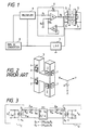
- the vibrating gyro of the present invention employs a resonator 3 which is essentially the same as shown in Fig. 2 in connection with the prior art.
- the resonator 3 is furnished with four piezoelectric devices 5 for detecting excited vibration that are in one-to one correspondence with driving piezoelectric devices 1, thereby forming a self-exciting oscillation circuit that uses output voltages of excited-vibration-detecting piezoelectric devices 5 to produce a drive voltage for the driving piezoelectric devices 1.
- a constant current circuit 6 is incorporated in the self-exciting oscillation circuit to ensure that the piezoelectric devices 1 will be driven by a constant AC current output having a constant amplitude.
- the self-exciting oscillation circuit formed in the embodiment shown in Fig. 1 includes a low-pass filter 7, a root-mean-square (RMS) DC converter 8 and a multiplier 9.
- the low-pass filter 7 rejects harmonic components from an AC voltage detected by the piezoelectric devices 5.
- the RMS DC converter 8 converts a filtered AC voltage into a root-mean-squared DC voltage, for example, by inverting minus half-waves with an operational amplifier and diodes and then rectifying the inverted voltage with a filter.
- the multiplier 9 has a function to supply the constant current circuit 6 with a regulated voltage on the basis of the filtered AC voltage and the root-mean-squared DC voltage.
- a function to supply the constant current circuit 6 with a regulated voltage on the basis of the filtered AC voltage and the root-mean-squared DC voltage For example, "Internal trimming high-precision IC multiplier”, AD632 and AD534 manufactured by Analog devices Inc. and "Analog multiplier", NJM4200 manufactured by New Japan Radio Co., Ltd. can be used as the multiplier 9.
- an operational amplifier A1 In the constant current circuit 6, the output of an operational amplifier A1 is fed back to the negative input thereof through a resistance R4 (e.g. 11 k ⁇ ). A voltage generated at an end of a resistance R3 (e.g. 1 k ⁇ ) is divided by R2 (e.g. 10 k ⁇ ) and R5 (e.g. 10 k ⁇ ) and positively fed back to the operational amplifier A1. An additional operational amplifier A2 is included in the positive feedback circuit so as to reduce a possible current error.
- a resistance R4 e.g. 11 k ⁇
- a voltage generated at an end of a resistance R3 e.g. 1 k ⁇
- R2 e.g. 10 k ⁇
- R5 e.g. 10 k ⁇
- the driving piezoelectric devices 1 attached to the resonator 3 are oscillated by the self-excitation and driven with the constant AC current. If the resonator 3 is vibrated by driving the piezoelectric devices 1 with the constant AC current, its vibrational speed will not change in spite of the angular velocity being applied to the vibrating gyro. This is because the "constant current driving" means that the current ⁇ 0 flowing in the drive unit 3 in the overall equivalent circuit shown in Fig. 3 remains constant even if impedance Z xe varies.
- the "constant current driving" means that the resonator of the vibrating gyro is vibrating at the constant speed. If the vibrational speed is constant, a constant linear relationship is always maintained between the angular velocity and the Coriolis force as suggested by the equation (1), thereby enabling precise detection of the angular velocity applied to the gyro.
- the driving piezoelectric devices 1 are driven with the constant AC current in the self-exciting oscillation mode.
- the invention is not limited to this embodiment. That is, the excited-vibration-detecting piezoelectric devices 5 may be omitted and the driving piezoelectric devices 1 may be simply driven by a constant current circuit which is connected to an oscillation circuit.
- the concept of the present invention is applicable not only to the H-type vibrating gyro but also to a tuning fork type vibrating gyro, tuning bar type vibrating gyro, etc.
- the vibrating gyro of the present invention is driven with the constant AC current and this enables the resonator to be driven at the constant vibrating speed irrespective of the angular velocity being applied to it, thereby improving the precision of angular velocity detection.
Landscapes
- Physics & Mathematics (AREA)
- Engineering & Computer Science (AREA)
- General Physics & Mathematics (AREA)
- Radar, Positioning & Navigation (AREA)
- Remote Sensing (AREA)
- Gyroscopes (AREA)
Applications Claiming Priority (2)
| Application Number | Priority Date | Filing Date | Title |
|---|---|---|---|
| JP302541/87 | 1987-11-30 | ||
| JP62302541A JPH01143961A (ja) | 1987-11-30 | 1987-11-30 | 振動ジャイロの駆動方法 |
Publications (3)
| Publication Number | Publication Date |
|---|---|
| EP0318972A2 true EP0318972A2 (de) | 1989-06-07 |
| EP0318972A3 EP0318972A3 (en) | 1989-10-11 |
| EP0318972B1 EP0318972B1 (de) | 1993-02-03 |
Family
ID=17910212
Family Applications (1)
| Application Number | Title | Priority Date | Filing Date |
|---|---|---|---|
| EP88120004A Expired - Lifetime EP0318972B1 (de) | 1987-11-30 | 1988-11-30 | Schwingkreisel |
Country Status (3)
| Country | Link |
|---|---|
| EP (1) | EP0318972B1 (de) |
| JP (1) | JPH01143961A (de) |
| DE (1) | DE3878182T2 (de) |
Cited By (7)
| Publication number | Priority date | Publication date | Assignee | Title |
|---|---|---|---|---|
| FR2692349A1 (fr) * | 1992-06-11 | 1993-12-17 | Sagem | Gyromètre à poutre vibrante, à excitation piézo-électrique. |
| EP0578519A1 (de) * | 1992-06-11 | 1994-01-12 | Sagem Sa | Schwingstabdrehungsmesseinrichtung |
| FR2705147A1 (fr) * | 1993-05-10 | 1994-11-18 | Sagem | Dispositif gyrométrique à poutres vibrantes. |
| EP0773429A1 (de) | 1995-11-13 | 1997-05-14 | Sfim Industries | Gyrometer mit mechanischem Resonator |
| US6281619B1 (en) | 1997-05-09 | 2001-08-28 | Citizen Watch Co., Ltd. | Vibration gyro |
| US7441458B2 (en) * | 2004-01-20 | 2008-10-28 | Ngk Insulators, Ltd. | Systems for measuring physical quantities |
| US7481913B2 (en) | 2002-11-08 | 2009-01-27 | Denso Corporation | High-resolution gas concentration measuring apparatus |
Families Citing this family (4)
| Publication number | Priority date | Publication date | Assignee | Title |
|---|---|---|---|---|
| JP2559140Y2 (ja) * | 1989-11-17 | 1998-01-14 | 日本電気ホームエレクトロニクス株式会社 | 振動ジャイロ駆動装置 |
| JP2000009469A (ja) | 1998-06-18 | 2000-01-14 | Fujitsu Ltd | 圧電ジャイロおよびその駆動方法 |
| JP4569701B2 (ja) * | 2002-11-08 | 2010-10-27 | 株式会社デンソー | ガス濃度検出装置 |
| CN102493490A (zh) * | 2011-12-10 | 2012-06-13 | 徐州工程学院 | 能感知自身电阻变化的窨井盖 |
Family Cites Families (2)
| Publication number | Priority date | Publication date | Assignee | Title |
|---|---|---|---|---|
| US4479098A (en) * | 1981-07-06 | 1984-10-23 | Watson Industries, Inc. | Circuit for tracking and maintaining drive of actuator/mass at resonance |
| IL75916A (en) * | 1984-07-27 | 1990-01-18 | Watson Ind Inc | Angular rate sensor |
-
1987
- 1987-11-30 JP JP62302541A patent/JPH01143961A/ja active Pending
-
1988
- 1988-11-30 EP EP88120004A patent/EP0318972B1/de not_active Expired - Lifetime
- 1988-11-30 DE DE8888120004T patent/DE3878182T2/de not_active Expired - Fee Related
Cited By (9)
| Publication number | Priority date | Publication date | Assignee | Title |
|---|---|---|---|---|
| FR2692349A1 (fr) * | 1992-06-11 | 1993-12-17 | Sagem | Gyromètre à poutre vibrante, à excitation piézo-électrique. |
| EP0578519A1 (de) * | 1992-06-11 | 1994-01-12 | Sagem Sa | Schwingstabdrehungsmesseinrichtung |
| US5597955A (en) * | 1992-06-11 | 1997-01-28 | Societe D'applications Generales D'electricite Et De Mecanique Sagem | Vibrating beam gyroscopic measuring apparatus |
| FR2705147A1 (fr) * | 1993-05-10 | 1994-11-18 | Sagem | Dispositif gyrométrique à poutres vibrantes. |
| EP0773429A1 (de) | 1995-11-13 | 1997-05-14 | Sfim Industries | Gyrometer mit mechanischem Resonator |
| US6281619B1 (en) | 1997-05-09 | 2001-08-28 | Citizen Watch Co., Ltd. | Vibration gyro |
| US7481913B2 (en) | 2002-11-08 | 2009-01-27 | Denso Corporation | High-resolution gas concentration measuring apparatus |
| DE10352064B4 (de) * | 2002-11-08 | 2019-10-31 | Denso Corporation | Gaskonzentrationsmessgerät mit hohem Auflösungsvermögen |
| US7441458B2 (en) * | 2004-01-20 | 2008-10-28 | Ngk Insulators, Ltd. | Systems for measuring physical quantities |
Also Published As
| Publication number | Publication date |
|---|---|
| EP0318972B1 (de) | 1993-02-03 |
| DE3878182T2 (de) | 1993-05-27 |
| EP0318972A3 (en) | 1989-10-11 |
| JPH01143961A (ja) | 1989-06-06 |
| DE3878182D1 (de) | 1993-03-18 |
Similar Documents
| Publication | Publication Date | Title |
|---|---|---|
| EP0318972A2 (de) | Schwingkreisel | |
| JP4310571B2 (ja) | 静電容量検出型振動ジャイロ、および静電容量変化検出方法 | |
| CN1894558A (zh) | 借助转速科式陀螺测量转速/加速度的方法和实现该方法的科式陀螺 | |
| CN1922465B (zh) | 角速度传感器 | |
| KR100263246B1 (ko) | 진동자이로의검출회로및이를이용한진동자이로장치 | |
| US6177756B1 (en) | Piezoelectric gyro and method of driving the piezoelectric gyro | |
| US5861705A (en) | Tuning-fork vibratory gyro and sensor system using the same | |
| JPH1078326A (ja) | 角速度検出装置 | |
| JPH02218914A (ja) | 振動ジャイロ | |
| EP1004848B1 (de) | Drehgeschwindigkeitssensor | |
| JP2006010408A (ja) | 振動ジャイロ | |
| EP0825417A2 (de) | Winkelgeschwindigkeitsmessvorrichtung | |
| JP3674013B2 (ja) | 角速度検出装置 | |
| JP3714974B2 (ja) | 振動型角速度検出装置 | |
| JP4309160B2 (ja) | 超音波複合振動体の駆動方法 | |
| JP4449383B2 (ja) | 発振回路 | |
| JP3039625B2 (ja) | 角速度検出装置 | |
| JP3240071B2 (ja) | 超音波モータ駆動装置 | |
| JPH0949736A (ja) | 振動型ジャイロスコープの駆動装置 | |
| EP0683381A2 (de) | Vibrationskreisel | |
| JPH09311041A (ja) | 角速度検出装置 | |
| JP3958741B2 (ja) | 圧電振動ジャイロ用振動子 | |
| JP2624431B2 (ja) | 振動子の調整方法 | |
| JP3579878B2 (ja) | 圧電振動ジャイロ用駆動検出回路 | |
| JPH109872A (ja) | 角速度センサ |
Legal Events
| Date | Code | Title | Description |
|---|---|---|---|
| PUAI | Public reference made under article 153(3) epc to a published international application that has entered the european phase |
Free format text: ORIGINAL CODE: 0009012 |
|
| AK | Designated contracting states |
Kind code of ref document: A2 Designated state(s): DE FR GB |
|
| PUAL | Search report despatched |
Free format text: ORIGINAL CODE: 0009013 |
|
| AK | Designated contracting states |
Kind code of ref document: A3 Designated state(s): DE FR GB |
|
| 17P | Request for examination filed |
Effective date: 19900409 |
|
| 17Q | First examination report despatched |
Effective date: 19910529 |
|
| GRAA | (expected) grant |
Free format text: ORIGINAL CODE: 0009210 |
|
| AK | Designated contracting states |
Kind code of ref document: B1 Designated state(s): DE FR GB |
|
| REF | Corresponds to: |
Ref document number: 3878182 Country of ref document: DE Date of ref document: 19930318 |
|
| ET | Fr: translation filed | ||
| PLBE | No opposition filed within time limit |
Free format text: ORIGINAL CODE: 0009261 |
|
| STAA | Information on the status of an ep patent application or granted ep patent |
Free format text: STATUS: NO OPPOSITION FILED WITHIN TIME LIMIT |
|
| 26N | No opposition filed | ||
| PGFP | Annual fee paid to national office [announced via postgrant information from national office to epo] |
Ref country code: FR Payment date: 19981127 Year of fee payment: 11 |
|
| PGFP | Annual fee paid to national office [announced via postgrant information from national office to epo] |
Ref country code: DE Payment date: 19981130 Year of fee payment: 11 |
|
| PGFP | Annual fee paid to national office [announced via postgrant information from national office to epo] |
Ref country code: GB Payment date: 19981204 Year of fee payment: 11 |
|
| PG25 | Lapsed in a contracting state [announced via postgrant information from national office to epo] |
Ref country code: GB Free format text: LAPSE BECAUSE OF NON-PAYMENT OF DUE FEES Effective date: 19991130 |
|
| GBPC | Gb: european patent ceased through non-payment of renewal fee |
Effective date: 19991130 |
|
| PG25 | Lapsed in a contracting state [announced via postgrant information from national office to epo] |
Ref country code: FR Free format text: LAPSE BECAUSE OF NON-PAYMENT OF DUE FEES Effective date: 20000731 |
|
| PG25 | Lapsed in a contracting state [announced via postgrant information from national office to epo] |
Ref country code: DE Free format text: LAPSE BECAUSE OF NON-PAYMENT OF DUE FEES Effective date: 20000901 |
|
| REG | Reference to a national code |
Ref country code: FR Ref legal event code: ST |