EP0319143A2 - Energievernichtungsbehälter für Hochgeschwindigkeits Flüssigkeitsstrahlen - Google Patents
Energievernichtungsbehälter für Hochgeschwindigkeits Flüssigkeitsstrahlen Download PDFInfo
- Publication number
- EP0319143A2 EP0319143A2 EP88310287A EP88310287A EP0319143A2 EP 0319143 A2 EP0319143 A2 EP 0319143A2 EP 88310287 A EP88310287 A EP 88310287A EP 88310287 A EP88310287 A EP 88310287A EP 0319143 A2 EP0319143 A2 EP 0319143A2
- Authority
- EP
- European Patent Office
- Prior art keywords
- container
- jet
- suspensoids
- receptacle
- receptacle according
- Prior art date
- Legal status (The legal status is an assumption and is not a legal conclusion. Google has not performed a legal analysis and makes no representation as to the accuracy of the status listed.)
- Withdrawn
Links
Images


Classifications
-
- B—PERFORMING OPERATIONS; TRANSPORTING
- B24—GRINDING; POLISHING
- B24C—ABRASIVE OR RELATED BLASTING WITH PARTICULATE MATERIAL
- B24C3/00—Abrasive blasting machines or devices; Plants
-
- B—PERFORMING OPERATIONS; TRANSPORTING
- B26—HAND CUTTING TOOLS; CUTTING; SEVERING
- B26F—PERFORATING; PUNCHING; CUTTING-OUT; STAMPING-OUT; SEVERING BY MEANS OTHER THAN CUTTING
- B26F3/00—Severing by means other than cutting; Apparatus therefor
- B26F3/004—Severing by means other than cutting; Apparatus therefor by means of a fluid jet
- B26F3/008—Energy dissipating devices therefor, e.g. catchers; Supporting beds therefor
-
- Y—GENERAL TAGGING OF NEW TECHNOLOGICAL DEVELOPMENTS; GENERAL TAGGING OF CROSS-SECTIONAL TECHNOLOGIES SPANNING OVER SEVERAL SECTIONS OF THE IPC; TECHNICAL SUBJECTS COVERED BY FORMER USPC CROSS-REFERENCE ART COLLECTIONS [XRACs] AND DIGESTS
- Y10—TECHNICAL SUBJECTS COVERED BY FORMER USPC
- Y10T—TECHNICAL SUBJECTS COVERED BY FORMER US CLASSIFICATION
- Y10T83/00—Cutting
- Y10T83/364—By fluid blast and/or suction
Definitions
- This to invention relates to fluid jet cutting systems, and more specifically, to the energy-dissipating receptacle associated with such systems.
- Cutting by means of a high-velocity fluid jet is well known in the art.
- a fluid such as water
- a pressure of 55,0 ⁇ 0 ⁇ 0 ⁇ pounds per square inch (379.2MPa) is forces through a jewel nozzle having a diameter of 0.003 to 0.030 inches ( ⁇ 076 to .762mm) to generate a jet having a velocity of up to three times the speed of sound.
- the jet thus produced can be used to cut through a variety of metallic and non-metallic materials such as steel, aluminum, paper, rubber, plastics, Kevlar, gravite and food products.
- abrasive materials have been added to the jet stream to produce a so-called “abrasive-jet".
- the abrasive-jet is used to precisely and accurately cut a wide variety of exceptionally hard materials such as tool steel, armor plate, certain ceramics and bullet proof glass, as well as certain soft materials such as lead.
- Typical abrasive materials include garnet, silica and aluminum oxide having grit sizes of #36 throught #120 ⁇ .
- the term "fluid jet” is used generically to mean fluid jets and abrasive jets.
- a fluid jet cutting system typically includes a nozzle for producing an axially directed, high velocity cutting jet formed from a liquid; and means for positioning a workpiece axially downstream from the nozzle to be cut by said jet.
- Fluid-jet cutting systems have accordingly included an energy-dissipating receptacle for receiving the high-velocity jet of fluid after it emerges from the workpiece.
- U.S. Patents, 2,985,0 ⁇ 50 ⁇ and 3,212,378 disclose a catch tank containing water or other fluid above a resilient pad of rubber or neoprene or other elastomeric material. Spray rails are provided on each side of the tank with a water spray being directed downwardly over the liquid surface to blanket the vapors of the cutting fluid and prevent their disbursal in the area of the cutting machine.
- U.S. Patent 3,730 ⁇ ,0 ⁇ 40 ⁇ discloses an energy-absorbing receptacle containing a harden steel impact block at the bottom of the receptacle, and a frusto-conical baffle arrangement immediately adjacent the workpiece at the top of the receptacle.
- the jet passes into the receptacle, and through a liquid in the receptacle which absorbs a portion of the jet's energy.
- the jet thereafter impacts the steel block at the bottom of the receptacle.
- the orientation of the baffle plates are described as preventing sound, spray and vapor from passing back out of the entrance.
- EP 0 208 038 discloses an energy-dissipating receptacle, whose interior cavity has side-walls which generally converge in the direction of jet flow. A plurality of circulating suspensoids within the cavity are impinged upon by the jet to dissipate the jet's kinetic energy and its contents are hereby incorporated by reference.
- receptacles have certain design criteria in common.
- First means must be provided for the evacuation of spent fluid, kerf material and abrasive (in the case of abrasive jet cutting systems) from the receptacle.
- the entrance of the receptacle preferably includes a wear-resistant lining, despite the considerable added cost.
- Third, the substantial noise generated by the fluid jet entering into air after cutting the workpiece can be minimized by minimizing the open space between the cut material and the energy-dissipating interior of the receptacle. As those skilled in the art appreciate, noise is reduced to a minimum when there is direct contact between the energy-dissipating interior and the workpiece.
- an energy dissipating receptacle for receiving the jet of a fluid jet cutting system and comprising a container and a plurality of suspensoids within said container, characterised in that the container has a multiplicity of perforations which are insufficient in size to allow the passage of a majority of the suspensoids.
- a fluid jet cutting system including means for producing a cutting jet, means for positioning a workpiece in a cutting position, and means for dissipating energy from said fluid jet, the dissipating means comprising a receptacle according to to the first aspect.
- FIG. 1 a sectional isometric view, in schematic, is presented showing an energy-dissipating receptacle 10 ⁇ comprising a highly perforated structure 12, a supporting structure 14, and a basin 16.
- the top of the supporting structure 14 is closed by a generally planar cover plate 18.
- a jet-accommodating through-hole 20 ⁇ is formed in the cover plate 18 to permit entry of the fluid jet into the perforated structure 12 after the jet emerges from the workpiece.
- the energy-dissipating receptacle 10 ⁇ is illustrated adjacent a workpiece-supporting table 22.
- the workpiece-supporting surface of the table 22 conveniently includes a notch 24 sized to surround the cover plate 18.
- the cover plate 18 is preferably at the same level as the workpiece-supporting surface of the table, but may be slightly lower or slightly higher depending on the characteristics of the workpiece being cut. The level of the cover plate 18 may easily be adjusted by shims positioned between the cover plate 18 and supporting member 14.
- the table 22 may also be provided with integrated rollers 23 or other means for accommodating the sliding of the workpiece across the table's surface with minimal friction.
- the basin 16 is positioned within the support structure 14 to collect water, kerf material, and any abrasive material which emerges from the perforated structure 12 as the workpiece is cut.
- the collected matter may be conveniently pumped from the basin into settling tanks, and the water recirculated to the jet-forming nozzle or, as described below, back into the perforated structure 12 as a cooling fluid.
- FIG 2 is a front, partially sectioned, elevation view in schematic, showing the perforated structure 12.
- the cover plate 18 includes a generally annular neck 32 extending downward from its underside.
- the perforated structure 12 is preferably formed from a limp or extremely flexible Kevlar mesh 28, but may alternatively be formed from similar mesh of any suitable textile or metal.
- the mesh material 28 is suspended from the cover plate 18 by a fastening belt 30 ⁇ which secures the upper edge of the mesh material to the downwardly extending, annular neck 32 formed on the underside of the cover plate 18.
- the mesh material is preferably one which is very flexible in all directions.
- the mesh can be thought of as similar to the chain-link garments warn by medieval knights.
- the mesh When made from Kevlar or other suitable fabric, the mesh has an appearance more like a window curtain. In either case, the structure is highly flexible in all directions.
- the interior of the mesh material 28 is substantially filled with a bed of suspensoids 34.
- the jet enters the mesh structure 12, through the hole 20 ⁇ in the cover plate 18, the jet encounters the bed of suspensoids therein. The majority of the jet's energy is expended as it strikes the bed of suspensoids, and the spent fluid escapes through the perforations of the mesh material to be collected in the basin 16 below.
- the jet tends to push the suspensoids out of the way as it enters and travels through the bed. Accordingly, the path cleared through the bed must be closed.
- the mesh structure negates the tendency of the impinging jet to push the suspensoids out of the way, by pushing inwardly against the suspensoid bed. This inwardly directed force is produced by the weight of the bed pressing downwardly against the bottom of the suspended structure 12. The downward force causes the sides of the mesh structure to become taut, thereby exerting the inwardly directed force against the sides of the bed. Since the spent fluid and waste material can freely escape the mesh material, a flushing action results which substantially discourages the caking of abrasive or other mateial within the suspensoid bed or against the interior of the receptacle.
- the preferred embodiment includes mesh material which is not self-supporting, but which is shaped to assume a "tear drop" configuration when filled with suspensoids and suspended from the cover plate.
- the relatively broader bottom portion of the mesh structure 12 enhances jet dissipation, since the jet spreads as it penetrates the suspensoids bed.
- the mesh material may be deformed to either increase the density of the suspensoid bed or to force the suspensoid bed upward to a position abutting the underside of the cover plate 18.
- means 36 for compressing the interior volume of the mesh structure is schematically illustrated in Figure 2 as comprising a block of material which is moved upward against the bottom of the mesh structure 12.
- the compression of the internal mesh volume can also be used as a noise-reduction measure. Because a substantial amount of noise is generated when the fluid jet enters into air after emerging from the workpiece, minimization of the open space between the workpiece and the suspensoids bed consequently minimizes the noise. Accordingly, the aforedescribed compression in the mesh's internal volume can be utilized to force the suspensoids bed upward so that its upper level abuts the underside of the cover plate 18, essentially eliminating the free air space between the workpiece and bed.
- a perforated cooling tube 38 is accordingly disposed about the inside diameter of the annular neck 32 to circumvent the upper portion of the mesh container 12.
- the tube 38 is coupled to a source of cooling fluid, such as the settling tanks to which the spent jet fluid is directed, to distribute relatively cool water onto the suspensoid bed during the cutting operation.
- a suitable mesh structure has been found to have a height of betwen 80 ⁇ mm and 20 ⁇ 0 ⁇ mm.
- the inner diameter of the neck 32 is preferably not smaller than 60 ⁇ millimeters, in order to avoid damage to the mesh material and the cooling tube by the deflected jet.
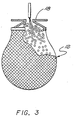
- the cover plate 18 may be modified to prevent splash back of the jet by providing a downwardly diverging, generally conically shaped entrance 40 ⁇ for the fluid jet as it enters the mesh structure 12.
- an alternative embodiment can be used with so called "X-Y” cutting systems, wherein the nozzle moves with respect to the receptacle.
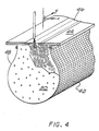
- These cutting systems are capable of cutting a workpiece in two orthogonal directions which are both normal to the axis of jet travel. As shown in Figure 4, the two cutting directions are conveniently referred to as the "X" direction and the "Y" direction.
- energy-dissipating receptacles utilized in "x-y" cutting systems can move in one of the two directions with the nozzle, while being structured to capture the fluid jet as the nozzle moves with respect to the receptacle in the second of the two directions.
- the embodiment illustrated in Figure 4 moves with the nozzle in the "X” direction, while accommodating the relative movement of the nozzle in the "Y” direction.
- the mesh structure 42 is fastened to a cover plate 44 having a transverse jet-accommodating slot 46.
- the slot 46 permits the jet to enter the interior of the mesh structure as the nozzle moves in the "Y" direction.
- a generally rectangular length of mesh material may conveniently be fastened to the underside of a cover plate 44 of elongate shape in the "Y" direction.
- the resulting mesh structure has a generally "U” shaped cross section, but more preferably the same tear-drop shaped cross-section illustrated in the foregoing Figures.
- the opposing ends 48 of the mesh structure are closed by perforated end plates 50 ⁇ having the contour of the desired cross-section.
- the end plates 50 ⁇ should not be positioned closer than approximately 25 cm to the closest point at which a cut is to be made, because an end plate creates a rigidity in the structure which hampers the path-closing function of the mesh.
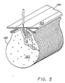
- the illustrated embodiment in Figure 4 provides the same characteristics and advantages attributed to the embodiment illustrated in Figure 2. Additionally, the embodiment illustrated in Figure 4 may be modified as illustated in Figure 5 to provide a downwardly diverging entrance similar to entrance 40 ⁇ in Figure 3.
Landscapes
- Engineering & Computer Science (AREA)
- Mechanical Engineering (AREA)
- Life Sciences & Earth Sciences (AREA)
- Forests & Forestry (AREA)
- Perforating, Stamping-Out Or Severing By Means Other Than Cutting (AREA)
Applications Claiming Priority (2)
| Application Number | Priority Date | Filing Date | Title |
|---|---|---|---|
| US12677487A | 1987-11-30 | 1987-11-30 | |
| US126774 | 1987-11-30 |
Publications (2)
| Publication Number | Publication Date |
|---|---|
| EP0319143A2 true EP0319143A2 (de) | 1989-06-07 |
| EP0319143A3 EP0319143A3 (de) | 1990-03-14 |
Family
ID=22426585
Family Applications (1)
| Application Number | Title | Priority Date | Filing Date |
|---|---|---|---|
| EP19880310287 Withdrawn EP0319143A3 (de) | 1987-11-30 | 1988-11-02 | Energievernichtungsbehälter für Hochgeschwindigkeits Flüssigkeitsstrahlen |
Country Status (6)
| Country | Link |
|---|---|
| US (1) | US4864780A (de) |
| EP (1) | EP0319143A3 (de) |
| JP (1) | JPH01234200A (de) |
| KR (1) | KR890007847A (de) |
| CN (1) | CN1034328A (de) |
| AU (1) | AU2399288A (de) |
Cited By (3)
| Publication number | Priority date | Publication date | Assignee | Title |
|---|---|---|---|---|
| EP0371394A3 (en) * | 1988-11-28 | 1990-08-22 | Durkopp Systemtechnik Gmbh | Cutting bed |
| EP0594092A1 (de) * | 1992-10-17 | 1994-04-27 | SÄCHSISCHE WERKZEUG UND SONDERMASCHINEN GmbH | Fangeinrichtung für Fluidstrahlschneidanlagen |
| EP0983827A1 (de) * | 1998-08-31 | 2000-03-08 | Bystronic Laser AG | Wasserstrahl-Schneideanlage |
Families Citing this family (19)
| Publication number | Priority date | Publication date | Assignee | Title |
|---|---|---|---|---|
| US5127199A (en) * | 1991-01-08 | 1992-07-07 | Progressive Blasting Systems, Inc. | Abrasive water jet catch tank media transporting means |
| JPH0737000B2 (ja) * | 1991-10-14 | 1995-04-26 | 澁谷工業株式会社 | 二重構造式キャッチャ |
| DE4235091C2 (de) * | 1992-10-17 | 2001-09-06 | Trumpf Sachsen Gmbh | Flüssigkeits- und Abrasivmittelzuführung für eine Fluidstrahlschneidanlage |
| US5831224A (en) * | 1995-04-07 | 1998-11-03 | Design Systems, Inc. | Noise reduction system for fluid cutting jets |
| US5782673A (en) * | 1996-08-27 | 1998-07-21 | Warehime; Kevin S. | Fluid jet cutting and shaping system and method of using |
| US5980372A (en) * | 1997-11-25 | 1999-11-09 | The Boeing Company | Compact catcher for abrasive waterjets |
| US20060180579A1 (en) * | 2005-02-11 | 2006-08-17 | Towa Intercon Technology, Inc. | Multidirectional cutting chuck |
| JP5030557B2 (ja) * | 2006-11-27 | 2012-09-19 | 東芝機械株式会社 | 液体ホーニング加工に用いる摩耗防止用遮蔽具 |
| JP5766493B2 (ja) * | 2011-04-13 | 2015-08-19 | 三菱重工業株式会社 | アブレイシブウォータージェット加工装置 |
| US8894468B2 (en) | 2012-05-16 | 2014-11-25 | Flow International Corporation | Fluid jet receptacle with rotatable inlet feed component and related fluid jet cutting system and method |
| US9358668B2 (en) * | 2012-07-19 | 2016-06-07 | Ascent Aerospace, Llc | Fluid jet receiving receptacles and related fluid jet cutting systems |
| US9242294B2 (en) | 2012-09-27 | 2016-01-26 | General Electric Company | Methods of forming cooling channels using backstrike protection |
| US9238265B2 (en) | 2012-09-27 | 2016-01-19 | General Electric Company | Backstrike protection during machining of cooling features |
| US9573289B2 (en) * | 2013-10-28 | 2017-02-21 | Flow International Corporation | Fluid jet cutting systems |
| US9278462B2 (en) | 2013-11-20 | 2016-03-08 | General Electric Company | Backstrike protection during machining of cooling features |
| CN107073738A (zh) * | 2014-10-24 | 2017-08-18 | 福伊特专利有限公司 | 水射流切割装置 |
| DE102015118610A1 (de) * | 2015-10-30 | 2017-05-04 | Nienstedt Gmbh | Vorrichtung zum Zerteilen von Lebensmitteln |
| CN107717754A (zh) * | 2017-11-24 | 2018-02-23 | 无锡市日升机械厂 | 人工操作箱型精密喷砂机 |
| CN112388514A (zh) * | 2019-08-16 | 2021-02-23 | 公准精密工业股份有限公司 | 水刀废水收集装置 |
Family Cites Families (10)
| Publication number | Priority date | Publication date | Assignee | Title |
|---|---|---|---|---|
| CA921139A (en) * | 1971-02-03 | 1973-02-13 | Amerace Esna Corporation | Shielding tape grounding device for high voltage cables |
| US3730040A (en) * | 1971-08-17 | 1973-05-01 | Bendix Corp | Energy absorber for high pressure fluid jets |
| DE2720547A1 (de) * | 1976-05-07 | 1977-11-24 | Shoe & Allied Trades Res Ass | Vorrichtung und verfahren zum duesenstrahlschneiden |
| US4312254A (en) * | 1977-10-07 | 1982-01-26 | Gerber Garment Technology, Inc. | Fluid jet apparatus for cutting sheet material |
| US4532949A (en) * | 1982-09-29 | 1985-08-06 | The Boeing Company | Energy absorber for high energy fluid jet |
| FR2534516B1 (fr) * | 1982-10-19 | 1986-08-08 | Aerospatiale | Appareil de decoupe par jet de fluide haute pression |
| FR2553330B1 (fr) * | 1983-10-17 | 1988-04-22 | Aerospatiale | Machine de decoupe de matiere en bande par jet fluide haute pression |
| US4669229A (en) * | 1985-07-10 | 1987-06-02 | Flow Systems, Inc. | Energy dissipating receptacle for high-velocity fluid jet |
| US4698939A (en) * | 1985-11-08 | 1987-10-13 | Flow System, Inc. | Two stage waterjet and abrasive jet catcher |
| US4651476A (en) * | 1986-05-07 | 1987-03-24 | Flow Systems, Inc. | Compact receptacle with automatic feed for dissipating a high-velocity fluid jet |
-
1988
- 1988-10-19 AU AU23992/88A patent/AU2399288A/en not_active Abandoned
- 1988-11-02 EP EP19880310287 patent/EP0319143A3/de not_active Withdrawn
- 1988-11-27 US US07/126,774 patent/US4864780A/en not_active Expired - Lifetime
- 1988-11-28 KR KR1019880015668A patent/KR890007847A/ko not_active Ceased
- 1988-11-29 JP JP63299783A patent/JPH01234200A/ja active Pending
- 1988-11-30 CN CN88108203A patent/CN1034328A/zh active Pending
Cited By (5)
| Publication number | Priority date | Publication date | Assignee | Title |
|---|---|---|---|---|
| EP0371394A3 (en) * | 1988-11-28 | 1990-08-22 | Durkopp Systemtechnik Gmbh | Cutting bed |
| EP0594092A1 (de) * | 1992-10-17 | 1994-04-27 | SÄCHSISCHE WERKZEUG UND SONDERMASCHINEN GmbH | Fangeinrichtung für Fluidstrahlschneidanlagen |
| DE4235090A1 (de) * | 1992-10-17 | 1994-06-23 | Saechsische Werkzeug Und Sonde | Flächenüberstreichender Liniencatcher für eine Fluidstrahlschneidanlage |
| DE4235090C2 (de) * | 1992-10-17 | 1998-09-03 | Saechsische Werkzeug Und Sonde | Flächenüberstreichender Liniencatcher (Fangeinrichtung) für eine Fluidstrahlschneidanlage |
| EP0983827A1 (de) * | 1998-08-31 | 2000-03-08 | Bystronic Laser AG | Wasserstrahl-Schneideanlage |
Also Published As
| Publication number | Publication date |
|---|---|
| CN1034328A (zh) | 1989-08-02 |
| KR890007847A (ko) | 1989-07-06 |
| EP0319143A3 (de) | 1990-03-14 |
| AU2399288A (en) | 1989-06-01 |
| US4864780A (en) | 1989-09-12 |
| JPH01234200A (ja) | 1989-09-19 |
Similar Documents
| Publication | Publication Date | Title |
|---|---|---|
| US4864780A (en) | Energy-dissipating receptacle for high velocity fluid jets | |
| US4501182A (en) | Apparatus for cutting by means of a high pressure fluid jet | |
| US4669229A (en) | Energy dissipating receptacle for high-velocity fluid jet | |
| EP0646422A1 (de) | Gerät und Verfahren zum Reinigen von Geweben | |
| US3730040A (en) | Energy absorber for high pressure fluid jets | |
| EP0223372A1 (de) | Strahlauffangkammer für eine Flüssigkeitsstrahl-Schneideinrichtung | |
| JP2671027B2 (ja) | 紙ウェブにクレープをつける時に放出されるちりを除去するための方法及び装置 | |
| EP0244966B1 (de) | Energievernichtungsbehälter für ein Flüssigkeitsstrahl-Schneidsystem | |
| US5803955A (en) | Apparatus for dust control | |
| JP2983916B2 (ja) | ダスト捕集装置 | |
| JP4659912B2 (ja) | 湿式集塵装置 | |
| US5980372A (en) | Compact catcher for abrasive waterjets | |
| US4758284A (en) | Cutting apparatus receptacle device and method of using same | |
| WO1997011814A1 (en) | A method and apparatus for cutting the edge of a moving paper web | |
| JP2002239775A (ja) | レーザ切断方法および切断装置 | |
| DE102004060849B3 (de) | Vorrichtung zur Entfernung von Bearbeitungsstaub, insbesondere Schnittstaub | |
| EP0590749A1 (de) | Mechanismus zur Verhinderung der Blockierung eines Filters | |
| JP2002059361A (ja) | 半導体製造装置及びその製造方法 | |
| DK0391441T3 (da) | Transportabelt blæsningsapparat til afslidningsblæsning af vægflader | |
| JPH01216799A (ja) | ウオータジェット切断装置のキャッチャー | |
| US4637302A (en) | Air supply device | |
| CA1046012A (en) | Waste separator device with air scrubber | |
| CN115816074B (zh) | 一种具有冲孔机构的焊接装置 | |
| WO2000018551A2 (en) | Improvements in and relating to fluid cutting operations | |
| US4070799A (en) | Reinforced finger seal for shot blast cabinets and the like |
Legal Events
| Date | Code | Title | Description |
|---|---|---|---|
| PUAI | Public reference made under article 153(3) epc to a published international application that has entered the european phase |
Free format text: ORIGINAL CODE: 0009012 |
|
| AK | Designated contracting states |
Kind code of ref document: A2 Designated state(s): AT BE CH DE ES FR GB GR IT LI LU NL SE |
|
| PUAL | Search report despatched |
Free format text: ORIGINAL CODE: 0009013 |
|
| AK | Designated contracting states |
Kind code of ref document: A3 Designated state(s): AT BE CH DE ES FR GB GR IT LI LU NL SE |
|
| STAA | Information on the status of an ep patent application or granted ep patent |
Free format text: STATUS: THE APPLICATION IS DEEMED TO BE WITHDRAWN |
|
| 18D | Application deemed to be withdrawn |
Effective date: 19900915 |