EP0319164A2 - Dispositif de balayage à laser - Google Patents
Dispositif de balayage à laser Download PDFInfo
- Publication number
- EP0319164A2 EP0319164A2 EP88310804A EP88310804A EP0319164A2 EP 0319164 A2 EP0319164 A2 EP 0319164A2 EP 88310804 A EP88310804 A EP 88310804A EP 88310804 A EP88310804 A EP 88310804A EP 0319164 A2 EP0319164 A2 EP 0319164A2
- Authority
- EP
- European Patent Office
- Prior art keywords
- window
- laser beam
- housing
- body portion
- power supply
- Prior art date
- Legal status (The legal status is an assumption and is not a legal conclusion. Google has not performed a legal analysis and makes no representation as to the accuracy of the status listed.)
- Withdrawn
Links
Images


Classifications
-
- G—PHYSICS
- G06—COMPUTING OR CALCULATING; COUNTING
- G06K—GRAPHICAL DATA READING; PRESENTATION OF DATA; RECORD CARRIERS; HANDLING RECORD CARRIERS
- G06K7/00—Methods or arrangements for sensing record carriers, e.g. for reading patterns
- G06K7/10—Methods or arrangements for sensing record carriers, e.g. for reading patterns by electromagnetic radiation, e.g. optical sensing; by corpuscular radiation
- G06K7/10544—Methods or arrangements for sensing record carriers, e.g. for reading patterns by electromagnetic radiation, e.g. optical sensing; by corpuscular radiation by scanning of the records by radiation in the optical part of the electromagnetic spectrum
- G06K7/10821—Methods or arrangements for sensing record carriers, e.g. for reading patterns by electromagnetic radiation, e.g. optical sensing; by corpuscular radiation by scanning of the records by radiation in the optical part of the electromagnetic spectrum further details of bar or optical code scanning devices
- G06K7/10881—Methods or arrangements for sensing record carriers, e.g. for reading patterns by electromagnetic radiation, e.g. optical sensing; by corpuscular radiation by scanning of the records by radiation in the optical part of the electromagnetic spectrum further details of bar or optical code scanning devices constructional details of hand-held scanners
-
- G—PHYSICS
- G06—COMPUTING OR CALCULATING; COUNTING
- G06K—GRAPHICAL DATA READING; PRESENTATION OF DATA; RECORD CARRIERS; HANDLING RECORD CARRIERS
- G06K7/00—Methods or arrangements for sensing record carriers, e.g. for reading patterns
- G06K7/10—Methods or arrangements for sensing record carriers, e.g. for reading patterns by electromagnetic radiation, e.g. optical sensing; by corpuscular radiation
- G06K7/10544—Methods or arrangements for sensing record carriers, e.g. for reading patterns by electromagnetic radiation, e.g. optical sensing; by corpuscular radiation by scanning of the records by radiation in the optical part of the electromagnetic spectrum
- G06K7/10821—Methods or arrangements for sensing record carriers, e.g. for reading patterns by electromagnetic radiation, e.g. optical sensing; by corpuscular radiation by scanning of the records by radiation in the optical part of the electromagnetic spectrum further details of bar or optical code scanning devices
- G06K7/1098—Methods or arrangements for sensing record carriers, e.g. for reading patterns by electromagnetic radiation, e.g. optical sensing; by corpuscular radiation by scanning of the records by radiation in the optical part of the electromagnetic spectrum further details of bar or optical code scanning devices the scanning arrangement having a modular construction
Definitions
- This invention relates to laser scanners and more particularly to hand held laser scanners, e.g of the type used within supermarkets and the like to read the UPC bar codes found on grocery packaging.
- a hand held laser scanning apparatus comprising a housing comprising a body portion and a handle portion, the housing containing a laser beam generator, a power supply therefor and optical components characterised in that the laser beam generator and the power supply are secured together to form a replaceable unit which is releasably mounted within the handle portion.
- optical components are exclusively located within the body portion so that removal of the replaceable unit cannot damage the optical components.
- a laser scanner including means mounted adjacent the window for adjusting the width of the beam.
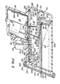
- Apparatus 20 comprises a compact ergonomic housing 22 (Figure 1), a laser tube and associated high voltage power supply sub-assembly 24 ( Figures 3 and 4), a beam folding and sweeping optics and motor subassembly 26, a photodetector and associated amplification and signal processing subassembly 28, a releasable input/output cable connector or plug 30, an associated input/output cable 32, and an on/off trigger assembly 34.
- the housing 22 includes a cylindrical handgrip portion 36 and an upper body portion 38.
- the body portion 38 is of generally parallelopiped shape, including a top wall 38A, an opposed pair of side walls 38B, a rear wall 38C, a front wall 38D (Fig 3) and a bottom wall 38E.
- the housing 22 is moulded from a relatively rigid plastics, such as a polycarbonate sold by the General Electric Company of America under the designation LEXAN.
- the plastic may be impregnated with e.g nickel particles to provide electrical shielding.
- the front wall 38D includes an opening in which a window 40 formed of an anti- reflective, wave-length selective glass, or other beam transparent material, e.g., plastic, is located.
- the laser tube and associated high voltage power supply subassembly 24 is mounted within the housing's handle portion 36, and the other two subassemblies 26 and 28 are mounted within the body portion 38.
- the body portion 38 of the housing 22 is split horizontally along a peripheral seam line 42 to provide a removable upper cap or cover 44 so that access may be provided for the components mounted within the body portion 38.
- the lower (free end) of the handle portion 36 is closed by a releasably securable cap 46 to provide access to the subassembly 24.
- Power for the device 20 is provided by either a 115 volt AC power pack (not shown), or a 24 volt battery-powered pack unit (not shown) including rechargeable batteries, or by plus 12 volts DC from a host terminal (not shown), via conductors within the cable 32 and which connects via a plug and socket 30 to the wiring harness 60 inside the housing.
- the wiring harness 60 is releasably connected to the high voltage power supply 66 of the subassembly 24.
- the cable 32 also contains further conductors for the passage of data signals between the device 20 and a host terminal.
- the subassembly 24 comprises a conventional glass laser tube 62, a printed circuit board or card 64, and a high voltage power supply 66 of conventional, switchmode design.
- the components forming the high voltage power supply 66 as well as a conventional ballast resistor assembly are mounted on one side of the card 64.
- a shield 68 formed of a laminated sheet comprising an outer layer of an electrically conductive material, e.g copper, and an inner layer of an electrically insulating material, e.g MYLAR 68A, is wrapped about the high voltage power supply components 66 and the printed circuit card 64.
- the copper layer is earthed to electrically shield the device 20 from the power supply 66.
- the laser tube 62 is of conventional helium neon type and includes a laser light emitting end face 78, which is preferably ground to focus the laser beam.
- the laser tube 62 is electrically connected to the power supply components 66 and is mounted onto the outside of the copper layer of the shield 68 by pieces of e.g resilient foam or RTV adhesive 70 placed between the shield 68 and the tube 62, and further pieces 76 placed between the inner surface of the housing's handle 36 and the outer surface of the laser tube assembly. In such a way the tube can absorb shock and withstand decelerations of 1400 MS ⁇ 2 or more without damage.
- an opposed pair of elongated recesses or slots 72 extend within the inner wall of the handle portion 36 parallel to the longitudinal axis thereof.
- the opposed side edges of the printed circuit board 64 include at least two spaced apart ears or tabs 74 which are shaped to be tightly disposed within the recess 72.
- the subassembly 24 may be placed within the handle portion 36 simply by removing the cap 46 and then sliding the subassembly 24 into the handle with the printed circuit card tabs 74 sliding along the recesses 72 to the condition shown in Figure 4.
- the cap 46 is replaced, once the necessary electrical connections have been made.
- a trigger assembly 34 is located within a recess in a thickened wall portion 48 at the front of the handle portion 36 underneath the body portion 38.
- the trigger assembly 34 is isolated from potentially high voltages on the nearby laser power supply subassembly 24 by an electrically insulating barrier 49 which consists of the housing's hand grip portion.
- the trigger assembly 34 comprises a button 50 mounted onto the actuator of a conventional push-button electrical switch 52 which is electrically and releasably connected to the subassembly 28 via conductors 54.
- a plate 55 formed of an electrically insulating material is mounted over the opening through which the conductors 54 extend.
- a rubber cover 57 is mounted over the top end of the high voltage power supply assembly 24. The plate 55 and cover 57 serve as additional electrical insulators, while the plate 55 also serves as a moisture seal.
- the subassembly 26 comprises a stepper motor 80 which rotates mirrors 86, 88 to sweep the laser beam.
- the motor 80 includes a housing 90 mounted within the body portion 38 of the housing 22 which is located and adhered upon positioning studs (not shown) which extend from the bottom wall of the body portion 38 adjacent the back wall 38C.
- a mounting bracket 84 is mounted on top of the motor's housing 90 and is generally a V-shaped planar member (Figure 2) having a pair of legs 92, each of which is releasably secured to the top of the motor housing 90 by threaded fasteners 94.
- bracket 84 At the apex of bracket 84 is an angled flange 96 which includes a portion extending at an approximate 45 degree angle to the plane of the bracket 84.
- Mounted on the inside surface of the angled portion of the flange 96 is a deflecting mirror 82 which deflects the laser beam 56 from the tube 62 toward the beam sweeping (outgoing) mirror 86.
- the mirror 86 is of generally planar shape (but may be concave) and also serves as a beam shaping element.
- the outgoing mirror 86 is mounted by a bracket 98 and a set screw 102 on the output shaft 100 of the motor 80.
- the output shaft 100 is arranged to be reciprocated by the motor through an arc of approximately 14° -22° (i.e., plus or minus 7° - 11° from a neutral central position.
- the returning light 58 from the bar code is arranged to impinge on a receiving or collecting mirror 88.
- the collecting mirror 88 is spherical so that it will focus the light for receipt by a photodetector 110 of the subassembly 28.
- the focal length of mirror 88 is preferably in the order of 100 millimeters or more.
- the spherical collecting mirror 88 is mounted on a bracket 104, which is mounted via a set screw 102 on the output shaft 100 of the motor 60.
- the subassembly 28 comprises a printed circuit board 106 on which are mounted signal processing circuitry and associated components 108, a light-receiving photodetector 110, a box-like filter and mounting bracket subassembly 112 and an incoming light deflecting mirror 114.
- the signal processing circuit board 106 is mounted within the body portion 38 upon plural positioning studs 120.
- the studs 120 project upwards from the wall 38E of the housing and extend through associated openings 122 in the printed circuit board.
- the printed circuit board 106 includes a central opening 132 through which the laser beam 56 passes from the laser tube 62 to the mirror 82 and also includes a second larger opening 134 through which the housing 90 of the motor 60 passes.
- the components 108 are of known type and comprise a photocell 110, a very high gain photocell preamplifier and associated amplifier, a microprocessor and various associated signal processing circuitry, as well as the low voltage power supply for the apparatus 20.
- the device also includes two light emitting diodes 124 and 126 which are mounted in the back wall 38C of the body portion 38.
- the LED 124 is connected by conductors 128 to the signal processor circuitry 108 so that it is illuminated whenever the trigger button 50 is depressed to indicate that the device is powered and is in the "scan mode" of operation.
- the other LED 126 is connected by conductcrs 130 to the signal processing circuitry and is arranged to be illuminated when the circuitry of the signal processing board has decoded the bar code symbol scanned.
- a box or shroud 112 is mounted on the top surface of the front end of the printed circuit board or card 106 and completely encloses the photocell 110 to prevent unwanted light from entering the photocell 110.
- the box 112 is preferably formed of metal to provide electrical shielding for the very high gain photocell preamplifier.
- a conventional band pass filter 116 is mounted within an opening (not shown) in the box 112 and is disposed over the photocell 110.
- the filter 116 and the optical components are designed to have a band pass for the wavelength of the particular laser beam e.g., if the laser is a helium-neon laser, the filter 116 has a band pass for radiation at a wavelength of 633 nanometers.
- the incoming light deflecting mirror 114 is mounted on a bracket 118 located on the front end of the box 112. The bracket 118 serves to further shield or shroud the filter and hence the photocell 110 from unwanted light entering the window 40.
- the incoming laser beam 58 is focussed by the collecting mirror 88 onto the mirror 114 which deflects the beam into the photocell 110.
- An electrically grounded copperfoil shield 119 (shown by the phantom lines in Figure 3) is provided under the front end of the board 106 and on the inner surface of front wall 38D to provide further electrical shielding.
- the front end of the device 20 includes a bumper 140 surrounding the window 40.
- the bumper 140 is preferably formed of a resilient material, such as rubber, to serve as a shock absorber to protect the device in case it is dropped on its front end.
- a beam width adjusting/attenuating component 150 is mounted within the bumper 140.
- the apparatus 20 projects a relatively wide laser beam out of the window 40 and while a wile beam is desirable for most scanning applications, in some cases it is preferable to have a narrower beam so that the beam can be aimed at only a single particular symbol out of a group of symbols e.g when scanning individual packages in a crowded shopping trolley.
- a beam width adjusting/attenuating component 150 comprises a movable curtain 150.
- the curtain 150 comprises a generally planar plate having a top edge 52, a pair of side edges 154 and 156, and a bottom edge 158.
- a first wide slot 160 extends across the centre of the top edge 152 and a second narrower slot 162 extends across the plate underneath the first slot 160.
- the curtain 150 is mounted over the front wall 38D of the housing with its edges 154 and 156 located within channels 164 ( Figure 3) in the inner vertical sides of the bumper 140.
- the curtain 150 is arranged to be slid within the channels 164 to various positions (heights) with respect to the window 40 to adjust the width of the projected beam to any one of four conditions.
- a first condition as shown in Figure 1, the curtain is moved down to the lowest position and as the beam sweeps to and fro, it is unimpeded by the curtain 150.
- the curtain 150 may be moved upwards to a second condition so that the edges of slot 160 block off the marginal ends of the beam.
- the curtain may then be moved further upwards to a third condition, so that slot 162 further blocks off the ends of the beam.
- the curtain is moved to the top of the channels 164, thereby entirely blocking the beam.
- depression of the trigger button 50 causes the laser beam generator 62 to produce a laser beam 56 which is directed out of the handle portion 36 through an opening 59 to impinge upon mirror 82.
- the laser beam is then deflected onto the outgoing mirror 86 which sweeps the beam through an arcuate path and directs it out of the front window 40 to impinge on a object e.g a bar code symbol (not shown) disposed up to 76 cm away from the window.
- the beam is then reflected by the bar codes, bars and spaces in a generally uniform spectral distribution, so that a portion of the reflected light 58 returns through the window 40.
- This returning light is focussed by the collecting mirror 88 onto the deflecting mirror 114, which directs it to the photodetector 110.
- the photodetector 110 and the associated signal processing circuitry produces digital TTL type signals which are decoded by a microprocessor (not shown) to provide conventional RS 232C signals (e.g ASCII characters). These data signals are sent via the cable 32 to any peripheral equipment such as a host computer, an electronic cash register, a memory bank, a modem, a printer, etc. Moreover, the output signals can be extended up to 288 kilobaud and may be used for light pen emulation.
- the apparatus 20 is capable of scanning at a very fast rate, e.g 35-70 scans per second, for decoding various conventional bar codes, e.g UPC Type A, D, E, EAN, etc located up to 75 cm from the window 40. Lower density symbols can be scanned from a distance of 102 cm.
- the width of the scan field is approximately 4.3 cm at the window 40 and 30 cm at a distance of 38 cm from the window.
- the depth of field can be up to 102 cm depending upon the width and size of the bar codes.
- the apparatus 20 is light weight, e.g approximately 340 gms, and extremely compact in size, e.g the body portion 38 can be approximately 9.3 cm long by 5.1 cm wide, and the overall height can be 19.9 cm and the handle portion 36 can be approximately 2.7 cm thick and 3.8 cm wide.
- the scanner is extremely easy to use without causing fatigue because the apparatus is light and the centre of gravity acts through the users' hand.
- the circuit board 64 holding the laser tube subassembly 24 is configured to fit tightly within the grooves 72 to enhance accurate positioning of the tube and hence accurate aiming of the beam.
- the printed circuit board 64 also stiffens the handgrip portion 36.
- the optical elements of the device are mounted on their respective subassemblies 26 and 28 in critical alignment with one another. However, the subassemblies themselves 26, 28 need not be as critically aligned with each other in the housing. It is an advantage of this construction that a separate optical bench is not required because the housing 22 itself is rigid enough to ensure that any deflections of the handle or thermal distortions of the housing will have no significant effect on the path of the laser beam.
- the modular nature of the subassembly 24, 26 and 28 mean that they are easily removable and the device is particularly easy to assemble and service.
- a plurality of keys is shown in ghost outline in the top wall of the housing 22. These keys 164 form a keyboard assembly so that data and/or instructions can be entered into the apparatus 20.
- a visual display panel 166 such as an alpha-numeric LCD display, may be provided to display the desired data or input instructions. Additional memory means (not shown) may also be included in such a device.
- the photocell 110 and filter 116 may be mounted generally vertically on the board 106 in the path of the incoming light from the collecting mirror, which arrangement eliminates the need for mirror 114 and its mounting bracket 118.
- a low power lightweight solid state e.g infra red laser may easily be substituted for the laser tube.
Landscapes
- Physics & Mathematics (AREA)
- Engineering & Computer Science (AREA)
- Electromagnetism (AREA)
- Artificial Intelligence (AREA)
- Toxicology (AREA)
- General Health & Medical Sciences (AREA)
- Health & Medical Sciences (AREA)
- Computer Vision & Pattern Recognition (AREA)
- General Physics & Mathematics (AREA)
- Theoretical Computer Science (AREA)
- Lasers (AREA)
- Facsimile Scanning Arrangements (AREA)
- Mechanical Optical Scanning Systems (AREA)
Applications Claiming Priority (2)
| Application Number | Priority Date | Filing Date | Title |
|---|---|---|---|
| US07/128,299 US4805175A (en) | 1987-12-03 | 1987-12-03 | Ultra-compact, hand-held laser scanner |
| US128299 | 1993-09-29 |
Publications (2)
| Publication Number | Publication Date |
|---|---|
| EP0319164A2 true EP0319164A2 (fr) | 1989-06-07 |
| EP0319164A3 EP0319164A3 (fr) | 1990-09-05 |
Family
ID=22434648
Family Applications (1)
| Application Number | Title | Priority Date | Filing Date |
|---|---|---|---|
| EP19880310804 Withdrawn EP0319164A3 (fr) | 1987-12-03 | 1988-11-16 | Dispositif de balayage à laser |
Country Status (3)
| Country | Link |
|---|---|
| US (1) | US4805175A (fr) |
| EP (1) | EP0319164A3 (fr) |
| JP (1) | JPH01189783A (fr) |
Cited By (4)
| Publication number | Priority date | Publication date | Assignee | Title |
|---|---|---|---|---|
| EP0464284A3 (en) * | 1990-06-26 | 1993-05-12 | Photographic Sciences Corporation | Scan modules for bar code readers |
| US5260554A (en) * | 1991-06-05 | 1993-11-09 | Psc, Inc. | System for automatically reading symbols, such as bar codes, on objects which are placed in the detection zone of a symbol reading unit, such as a bar code scanner |
| EP0498366A3 (fr) * | 1991-02-07 | 1994-03-16 | Psc Inc | |
| US5786581A (en) * | 1991-02-07 | 1998-07-28 | Psc Inc. | Optical system for scanning and recording bar codes which is adapted to be configured in a hand held unit |
Families Citing this family (47)
| Publication number | Priority date | Publication date | Assignee | Title |
|---|---|---|---|---|
| US5545889A (en) * | 1985-02-28 | 1996-08-13 | Swartz; Jerome | Portable laser diode scanning head |
| US5132870A (en) * | 1987-12-16 | 1992-07-21 | North American Philips Corporation | Ignitor circuit for discharge lamps with novel ballast |
| US5672860A (en) * | 1987-12-21 | 1997-09-30 | Norand Corporation | Integrated hand-held bar code processing device capable of automatic scan and data display |
| US5625180A (en) * | 1987-12-21 | 1997-04-29 | Norand Corporation | Data capture system with communicating and recharging docking apparatus and hand-held data terminal means cooperable therewith |
| US7712669B2 (en) * | 1988-01-14 | 2010-05-11 | Broadcom Corporation | Hand-held data capture system with interchangeable modules |
| US5304788A (en) * | 1988-10-31 | 1994-04-19 | Symbol Technologies, Inc. | Laser diode scanner with enhanced visibility at an aiming distance relative to the reading distance |
| US4962980A (en) * | 1989-01-23 | 1990-10-16 | Metrologic Instruments, Inc. | Laser scanner engine with folded beam path |
| US4930848A (en) * | 1989-01-26 | 1990-06-05 | Metrologic Instruments, Inc. | Portable laser scanner with integral scanner engine |
| US5179270A (en) * | 1989-05-08 | 1993-01-12 | Spectra-Physics, Inc. | Scanner system interface |
| USD317154S (en) | 1989-05-08 | 1991-05-28 | Ncr Corporation | Bar code scanner or similar article |
| US4969153A (en) * | 1989-07-24 | 1990-11-06 | Ncr Corporation | Laser tube and power supply |
| US5367151A (en) * | 1989-10-30 | 1994-11-22 | Symbol Technologies, Inc. | Slim scan module with interchangeable scan element |
| JP2787817B2 (ja) * | 1990-01-31 | 1998-08-20 | キヤノン株式会社 | 走査光学装置 |
| US6058000A (en) * | 1990-07-31 | 2000-05-02 | Intermec Ip Corp. | Method and apparatus for electromagnetic shielding and electrostatic discharge protection |
| AU4282593A (en) * | 1992-04-17 | 1993-11-18 | Spectra-Physics Scanning Systems, Inc. | Ultra-compact bar-code scanner |
| US5430558A (en) * | 1992-09-29 | 1995-07-04 | Sohaei; Frank | Portable optical scanner with integral audio recorder |
| CA2150698A1 (fr) * | 1992-12-04 | 1994-06-23 | Jay M. Eastman | Systemes et dispositifs de lecture de symboles optiques (codes a barres) |
| US5810005A (en) | 1993-08-04 | 1998-09-22 | Dublin, Jr.; Wilbur L. | Apparatus and method for monitoring intraocular and blood pressure by non-contact contour measurement |
| JP3379837B2 (ja) * | 1994-10-27 | 2003-02-24 | 富士通株式会社 | 光学読取装置 |
| DE69636183T2 (de) * | 1995-03-31 | 2007-03-29 | Lintec Corp. | Vorrichtung zur Prüfung von Halbleitersubstraten |
| JPH08315059A (ja) * | 1995-05-16 | 1996-11-29 | Asahi Optical Co Ltd | データシンボル読み取り装置 |
| JP3793600B2 (ja) * | 1996-02-20 | 2006-07-05 | 株式会社オプトエレクトロニクス | 光学的パターン読取装置 |
| JP3824357B2 (ja) * | 1996-09-27 | 2006-09-20 | 沖電気工業株式会社 | 光半導体装置 |
| US6338432B1 (en) * | 1997-02-19 | 2002-01-15 | Opticon Inc | Optical pattern reading apparatus with movable optical unit |
| US6592040B2 (en) * | 1998-03-20 | 2003-07-15 | Symbol Technologies, Inc. | Hand-held bar code reader with single printed circuit board |
| US6321990B1 (en) * | 1998-08-05 | 2001-11-27 | Symbol Technologies, Inc. | Scanner with shock-absorbing canopy overmolded with linear of housing |
| US6634558B1 (en) * | 1998-08-12 | 2003-10-21 | Symbol Technologies, Inc. | Optical code reader with hand mounted imager |
| US20030132291A1 (en) * | 2002-01-11 | 2003-07-17 | Metrologic Instruments, Inc. | Point of sale (POS) station having bar code reading system with integrated internet-enabled customer-kiosk terminal |
| US7100832B2 (en) * | 2000-04-18 | 2006-09-05 | Metrologic Instruments, Inc. | Bioptical laser scanning system providing 360° of omnidirectional bar code symbol scanning coverage at point of sale station |
| US7128266B2 (en) * | 2003-11-13 | 2006-10-31 | Metrologic Instruments. Inc. | Hand-supportable digital imaging-based bar code symbol reader supporting narrow-area and wide-area modes of illumination and image capture |
| US6749121B2 (en) * | 2001-10-19 | 2004-06-15 | Symbol Technologies, Inc. | Antenna assembly |
| US7296748B2 (en) | 2002-01-11 | 2007-11-20 | Metrologic Instruments, Inc. | Bioptical laser scanning system providing 360° of omnidirectional bar code symbol scanning coverage at point of sale station |
| US8002183B2 (en) * | 2005-10-20 | 2011-08-23 | Metrologic Instruments, Inc. | Scanner flipper integrity indicator |
| US7614561B2 (en) * | 2005-12-16 | 2009-11-10 | Metrologic Instruments, Inc. | Scanner flipper oscillation frequency detection and adjustment thereof |
| JP4994744B2 (ja) * | 2006-08-11 | 2012-08-08 | キヤノン株式会社 | 携帯型画像投射装置 |
| US8294969B2 (en) * | 2009-09-23 | 2012-10-23 | Metrologic Instruments, Inc. | Scan element for use in scanning light and method of making the same |
| US8059324B2 (en) * | 2009-09-23 | 2011-11-15 | Metrologic Instruments, Inc. | Scan element for use in scanning light and method of making the same |
| US8390909B2 (en) | 2009-09-23 | 2013-03-05 | Metrologic Instruments, Inc. | Molded elastomeric flexural elements for use in a laser scanning assemblies and scanners, and methods of manufacturing, tuning and adjusting the same |
| JP2012063278A (ja) * | 2010-09-16 | 2012-03-29 | Sanyo Electric Co Ltd | ビーム照射装置およびレーザレーダ |
| US8523076B2 (en) | 2012-01-10 | 2013-09-03 | Metrologic Instruments, Inc. | Omnidirectional laser scanning bar code symbol reader generating a laser scanning pattern with a highly non-uniform scan density with respect to line orientation |
| US9934416B2 (en) * | 2012-01-17 | 2018-04-03 | Honeywell International, Inc. | Industrial design for consumer device based scanning and mobility |
| US8915439B2 (en) | 2012-02-06 | 2014-12-23 | Metrologic Instruments, Inc. | Laser scanning modules embodying silicone scan element with torsional hinges |
| US8746563B2 (en) | 2012-06-10 | 2014-06-10 | Metrologic Instruments, Inc. | Laser scanning module with rotatably adjustable laser scanning assembly |
| US9304376B2 (en) | 2013-02-20 | 2016-04-05 | Hand Held Products, Inc. | Optical redirection adapter |
| TWI519050B (zh) * | 2015-01-20 | 2016-01-21 | 宇帷國際股份有限公司 | 電子裝置及其電路模組 |
| TWI522784B (zh) * | 2015-01-20 | 2016-02-21 | 宇帷國際股份有限公司 | 電子裝置 |
| US10063753B2 (en) * | 2016-04-22 | 2018-08-28 | Symbol Technologies, Llc | Imaging module for supporting printed circuit boards in a predetermined angular relationship inside an imaging reader, and method of assembly |
Family Cites Families (12)
| Publication number | Priority date | Publication date | Assignee | Title |
|---|---|---|---|---|
| US4496831A (en) * | 1980-02-29 | 1985-01-29 | Symbol Technologies, Inc. | Portable laser scanning system and scanning methods |
| US4387297B1 (en) * | 1980-02-29 | 1995-09-12 | Symbol Technologies Inc | Portable laser scanning system and scanning methods |
| US4593186A (en) * | 1980-02-29 | 1986-06-03 | Symbol Technologies, Inc. | Portable laser scanning system and scanning methods |
| US4409470A (en) * | 1982-01-25 | 1983-10-11 | Symbol Technologies, Inc. | Narrow-bodied, single-and twin-windowed portable laser scanning head for reading bar code symbols |
| US4460120A (en) * | 1982-01-25 | 1984-07-17 | Symbol Technologies, Inc. | Narrow bodied, single- and twin-windowed portable laser scanning head for reading bar code symbols |
| US4736095A (en) * | 1982-01-25 | 1988-04-05 | Symbol Technologies, Inc. | Narrow-bodied, single- and twin-windowed portable laser scanning head for reading bar code symbols |
| US4673805A (en) * | 1982-01-25 | 1987-06-16 | Symbol Technologies, Inc. | Narrow-bodied, single- and twin-windowed portable scanning head for reading bar code symbols |
| USD281977S (en) | 1983-08-22 | 1985-12-31 | Metrologic Instruments, Inc. | Portable hand-held laser scanner |
| US4575625A (en) * | 1983-09-27 | 1986-03-11 | Knowles Carl H | Integral hand-held laser scanner |
| US4607156A (en) * | 1984-03-26 | 1986-08-19 | Symbol Technologies, Inc. | Shock-resistant support structure for use in portable laser scanning heads |
| DE3508626C1 (de) * | 1985-03-11 | 1986-02-27 | Windmöller & Hölscher, 4540 Lengerich | Flachlege- und Abzugsvorrichtung fuer eine aus Kunststoff im Blasverfahren hergestellte Schlauchfolienbahn |
| US4694182A (en) * | 1986-02-27 | 1987-09-15 | Spectra-Physics, Inc. | Hand held bar code reader with modulated laser diode and detector |
-
1987
- 1987-12-03 US US07/128,299 patent/US4805175A/en not_active Expired - Lifetime
-
1988
- 1988-11-16 EP EP19880310804 patent/EP0319164A3/fr not_active Withdrawn
- 1988-11-29 JP JP63302122A patent/JPH01189783A/ja active Pending
Cited By (4)
| Publication number | Priority date | Publication date | Assignee | Title |
|---|---|---|---|---|
| EP0464284A3 (en) * | 1990-06-26 | 1993-05-12 | Photographic Sciences Corporation | Scan modules for bar code readers |
| EP0498366A3 (fr) * | 1991-02-07 | 1994-03-16 | Psc Inc | |
| US5786581A (en) * | 1991-02-07 | 1998-07-28 | Psc Inc. | Optical system for scanning and recording bar codes which is adapted to be configured in a hand held unit |
| US5260554A (en) * | 1991-06-05 | 1993-11-09 | Psc, Inc. | System for automatically reading symbols, such as bar codes, on objects which are placed in the detection zone of a symbol reading unit, such as a bar code scanner |
Also Published As
| Publication number | Publication date |
|---|---|
| US4805175A (en) | 1989-02-14 |
| JPH01189783A (ja) | 1989-07-28 |
| EP0319164A3 (fr) | 1990-09-05 |
Similar Documents
| Publication | Publication Date | Title |
|---|---|---|
| US4805175A (en) | Ultra-compact, hand-held laser scanner | |
| US5115120A (en) | Scan modules for bar code readers and in which scan elements are flexurally supported | |
| EP0455740B1 (fr) | Scanner laser portatif a module scanner integre | |
| US5949056A (en) | Method and apparatus for optically reading an information pattern | |
| US5475206A (en) | Scanner assembly | |
| US6491222B1 (en) | Optical path design for scanning assembly in compact bar code readers | |
| US6360949B1 (en) | Retro-reflective scan module for electro-optical readers | |
| US6592040B2 (en) | Hand-held bar code reader with single printed circuit board | |
| EP0449490B1 (fr) | Explorateur optique | |
| CA2143713C (fr) | Lecteur portatif | |
| EP0697674A1 (fr) | Lecteur de codes à barres | |
| AU2121699A (en) | One piece optical assembly for low cost optical scanner | |
| EP0318574B1 (fr) | Appareil de lecture optique | |
| WO1981001763A1 (fr) | Dispositif de balayage optique de caracteres | |
| EP0478376A2 (fr) | Dispositif de balayage optique | |
| EP0533366A2 (fr) | Dispositif et méthode de balayage optique | |
| US5979767A (en) | Portable multi-directional bar code scanner | |
| EP1308875A2 (fr) | Module de scanner à laser à haute vitesse à trajectoire de faisceau en accordeon | |
| EP0224996B1 (fr) | Appareil de balayage à laser | |
| US6702184B2 (en) | Collection optics for low profile single line scanning assembly in compact bar code readers | |
| EP0222388B1 (fr) | Appareil de balayage à laser | |
| GB2387701A (en) | Optical indicia scan module | |
| EP0532220A2 (fr) | Lecteur de code barre et sa manière de fonction | |
| EP0783157B1 (fr) | Montage simplifié et essai automatique de composants dans un système électro-optique pour lire | |
| JPH07134747A (ja) | バーコードリーダ |
Legal Events
| Date | Code | Title | Description |
|---|---|---|---|
| PUAI | Public reference made under article 153(3) epc to a published international application that has entered the european phase |
Free format text: ORIGINAL CODE: 0009012 |
|
| AK | Designated contracting states |
Kind code of ref document: A2 Designated state(s): AT BE CH DE ES FR GB GR IT LI LU NL SE |
|
| PUAL | Search report despatched |
Free format text: ORIGINAL CODE: 0009013 |
|
| AK | Designated contracting states |
Kind code of ref document: A3 Designated state(s): AT BE CH DE ES FR GB GR IT LI LU NL SE |
|
| STAA | Information on the status of an ep patent application or granted ep patent |
Free format text: STATUS: THE APPLICATION IS DEEMED TO BE WITHDRAWN |
|
| 18D | Application deemed to be withdrawn |
Effective date: 19910306 |