EP0319219B1 - Funkrufempfänger mit Funktion für Batterieschonung - Google Patents
Funkrufempfänger mit Funktion für Batterieschonung Download PDFInfo
- Publication number
- EP0319219B1 EP0319219B1 EP88311228A EP88311228A EP0319219B1 EP 0319219 B1 EP0319219 B1 EP 0319219B1 EP 88311228 A EP88311228 A EP 88311228A EP 88311228 A EP88311228 A EP 88311228A EP 0319219 B1 EP0319219 B1 EP 0319219B1
- Authority
- EP
- European Patent Office
- Prior art keywords
- paging
- power supply
- predetermined
- signal sequence
- pager
- Prior art date
- Legal status (The legal status is an assumption and is not a legal conclusion. Google has not performed a legal analysis and makes no representation as to the accuracy of the status listed.)
- Expired - Lifetime
Links
Images


Classifications
-
- H—ELECTRICITY
- H04—ELECTRIC COMMUNICATION TECHNIQUE
- H04B—TRANSMISSION
- H04B3/00—Line transmission systems
- H04B3/02—Details
- H04B3/44—Arrangements for feeding power to a repeater along the transmission line
-
- H—ELECTRICITY
- H04—ELECTRIC COMMUNICATION TECHNIQUE
- H04W—WIRELESS COMMUNICATION NETWORKS
- H04W52/00—Power management, e.g. Transmission Power Control [TPC] or power classes
- H04W52/02—Power saving arrangements
- H04W52/0209—Power saving arrangements in terminal devices
- H04W52/0212—Power saving arrangements in terminal devices managed by the network, e.g. network or access point is leader and terminal is follower
- H04W52/0216—Power saving arrangements in terminal devices managed by the network, e.g. network or access point is leader and terminal is follower using a pre-established activity schedule, e.g. traffic indication frame
-
- H—ELECTRICITY
- H04—ELECTRIC COMMUNICATION TECHNIQUE
- H04W—WIRELESS COMMUNICATION NETWORKS
- H04W88/00—Devices specially adapted for wireless communication networks, e.g. terminals, base stations or access point devices
- H04W88/02—Terminal devices
- H04W88/022—Selective call receivers
-
- Y—GENERAL TAGGING OF NEW TECHNOLOGICAL DEVELOPMENTS; GENERAL TAGGING OF CROSS-SECTIONAL TECHNOLOGIES SPANNING OVER SEVERAL SECTIONS OF THE IPC; TECHNICAL SUBJECTS COVERED BY FORMER USPC CROSS-REFERENCE ART COLLECTIONS [XRACs] AND DIGESTS
- Y02—TECHNOLOGIES OR APPLICATIONS FOR MITIGATION OR ADAPTATION AGAINST CLIMATE CHANGE
- Y02D—CLIMATE CHANGE MITIGATION TECHNOLOGIES IN INFORMATION AND COMMUNICATION TECHNOLOGIES [ICT], I.E. INFORMATION AND COMMUNICATION TECHNOLOGIES AIMING AT THE REDUCTION OF THEIR OWN ENERGY USE
- Y02D30/00—Reducing energy consumption in communication networks
- Y02D30/70—Reducing energy consumption in communication networks in wireless communication networks
Definitions
- This invention relates to the field of radio paging systems in which paging signals are broadcast from a base station to a plurality of pagers by way of radio channels and, more specifically, to a paging system in which the batteries of pagers are efficiently saved.
- all pagers in a paging system are divided into several groups and the supply of power to a radio receiver section from the battery is periodically turned off in a pager so that only paging signals to the group to which the pager belongs are received.
- Fig. 1 shows a known signal format used in a paging system with a conventional battery saving function.
- all pagers in the system are divided into M groups, for example, 15 groups.
- a base station repeatedly broadcasts a frame signal consisting of M group signals.
- Each group signal includes preamble words and N paging words (Fig. 1(b)) where N, for example, is 20.
- the preamble word includes a predetermined signal sequence for synchronization of received signals and a group designation signal for showing that the following paging words are addressed to pagers belonging to the group designated by the group designation signal.
- Each paging word includes data bits and check bits (Fig. 1(c)).
- the data bits consisting of X bits represents an identification number of paged (called) pagers.
- the check bits consisting of Y bits are for correcting an error in the data bits.
- the paging word consisting of data bits and check bits may be a so-called (31, 16) BCH code in which 15 check bits are appended to 16 data bits.
- the base station receives a paging request to a pager from a land line telephone via a paging exchange, the base station inserts an identification number corresponding to the paged pager into data bits of one of paging words when paging words of a group to which the pager belongs are to be broadcast. If a pager belongs to group 2, the pager automatically turns on power supply to a radio receiver section thereof only when paging words for group 2 are broadcast as shown in Fig. 2. This is indicated as the "reception state.” Since paging words are broadcast periodically at a predetermined time interval, (once per frame) if the pager once synchronizes to a timing schedule in which the paging words of group 2 are broadcast, turning on/off of power supply to a radio section is thereafter automatically repeated.
- a problem with the conventional battery saving technique is that power supply to the radio receiver section remains on throughout the duration when paging words to a group are to be broadcast whether paging words to a particular paging device of that group are actually broadcast or not. For example, in the middle of the night paging requests do not occur so frequently. Consequently, despite the fact that no paging words are broadcast to a pager, the pager will repeatedly turn on or off the power supply to the radio receiver section and consume the pager's battery wastefully. Furthermore, even when the paging word to a particular pager is to be broadcast, power supply to the radio receiver section is not turned off responsive to the detection of the paging word to the pager, but just turned off periodically in accordance with a battery saving cycle.
- GB-2 114 343 describes a prior system in which a "blank call pattern" is transmitted in response to which the reception controller of a pager is de-energised.
- this system still wastes power when there is no "blank call pattern" because the reception controller always remains energised for a fixed period of time in each cycle.
- the present invention provides a paging apparatus comprising receiving means for receiving signals broadcast over a predetermined radio channel, signal detecting means responsive to said receiving means for detecting synchronization signals and a predetermined signal sequence, power supply means for supplying said receiving means with power, power supply control means for controlling said power supply means, the power supply to said receiving means being periodically switched on for a predetermined period in response to the detecting of said synchronization signals and in the absence of said predetermined signal sequence, and being switched off when said predetermined signal sequence is detected, characterised in that said power supply means is also switched off immediately after reception of a paging signal for said apparatus.
- Figs. 3(a) to (c) and Figs. 4(a) and (b) are diagrams for explaining one example of a battery saving operation of a pager according to one embodiment of the present invention.
- a specific code is inserted in an area where paging word 1 would have been inserted at a base station in a conventional technique.
- the specific code consists of 16 bits of "1" followed by its check bits and is, consequently, distinguishable from any other paging words.
- a pager belonging to, for example, group 2 detects the specific code by comparing the received specific code with a specific code prestored in its memory after detecting a preamble word. Then the pager recognizes that there will not be any paging words for group 2 and turns off power supply to a radio receiver section of the pager immediately after detecting the specific code.
- the pager has at least one chance to get a paging signal even if the pager stops receiving signals for the duration in which n frames are broadcast.
- Figs. 5(a) to (b) are diagrams for explaining another example fo a battery saving opeation according to the embodiment of the present invention.
- the pager detects the paging word to the pager by comparing data bits in the paging word with a prestored unique identification number.
- a conventional pager continues to supply power to a radio section thereof through the duration when the paging words to the group to which the pager belongs are broadcast even after a paging word to the particular pager is detected.
- the pager turns off power supply to a radio section immediately after the paging word to the particular pager is detected even if other paging words for other pagers of the group are to be subsequently broadcast (Fig. 5(b)).
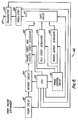
- Fig. 6 is a block diagram showing a modified arrangement of a base station according to the embodiment of the present invention.
- base station 600 comprises trunk circuit 601 for receiving paging requests with pager numbers to be paged from a paging telephone exchange and a memory circuit 602 for storing pager numbers to be paged, which are sent from trunk circuit 601.
- Base station 600 further comprises paging codes and specific codes generator 603 for generating data bits corresponding to the pager numbers to be paged or specific codes indicative of the absence of pager numbers to be paged and their check bits, idle codes generator 604 for generating idle codes indicative of vacancy of paging words, preamble words generator 605 for generating preamble words including synchronizing words and group designation signals, timing control circuit 606 for providing timing signals to paging codes and specific codes generator 603, and gate circuit 607.
- Gate circuit 607 selectively outputs signals provided by paging codes and specific codes generator 603, idle codes generator 604, or preamble words generator 605.
- Modulator 608 modulates an output signal from gate circuit 607 onto a radio carrier for transmission.
- Transmitter 609 transmits signals provided by modulator 608.
- Central processing unit (CPU) 610 controls the overall operations of base station 600.
- CPU 610 checks for the presence of paging numbers to be paged of a particular group in memory circuit 602 when paging words for the group are to be broadcast. If at least a paging number to be paged is stored in memory at that time, CPU 610 controls each circuit so that paging words corresponding to the paging numbers are broadcast as would occur in a conventional system. In this embodiment, a paging word is broadcast five times for each paging request.
- CPU 610 controls paging codes and specific codes generator 603 so that a specific code indicative of the absence of paging codes is generated from paging codes and specific codes generator 603 and controls timing control circuit 606 so that the specific code is followed by an idle code indicative of vacant paging words, which is generated in idle codes generator 604.
- These signals are broadcast via gate circuit 607, modulator 608, and transmitter 609 after transmission of a preamble word corresponding to the groups under control of CPU 610 over channel 611.
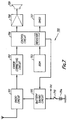
- Figure 7 is a block diagram showing an arrangement of paging apparatus according to the embodiment of the present invention.
- paging apparatus 700 comprises radio receiver circuit 701 for receiving paging signals broadcast from the base station over channel 611, error correcting circuit 702 for correcting errors in the data bits on the basis of the following check bits, read only memory (ROM) 703 for storing an identification number of the pager, specific code data and other permanently stored data, battery 704 for supplying power to each circuit, and battery saving circuit 705 for providing radio circuit 701 electric power from battery 704 in response to a control signal.
- Control circuit 706 checks for received paging signals, generates an alarm signal, and provides the control signal to battery saving circuit 705.
- Clock generator 707 applies clock signals to control circuit 706.
- Amplifier 708 amplifies the alarm signal from control circuit 706, and a loudspeaker 709 sounds an alarming beep tone responsive to the amplified alarm signal.
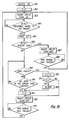
- the algorithm is typically stored in ROM 703 but may be stored in memory of control circuit 706.
- each circuit except radio circuit 701 is powered by battery 704.
- Count value C in a register of control circuit 706 is set to zero (step 802).
- the count value C represents how many times a paging word to the pager is detected.
- Control circuit 706 controls battery saving circuit 705 by sending the control signal so that radio circuit 701 is supplied with power from a battery 704 (step 803).
- a synchronization signal is detected.
- the synchronization signal is checked to determine whether the following group designation signal indicates the group to which the pager belongs.
- a preamble word consisting of synchronization signals and the group designation signal is detected (step 804) by comparing a received group designation number with one stored in memory 703.
- control circuit 706 sets timer 707 to zero (step 805) and checks the subsequent first paging word applied from radio circuit 701 via error correcting circuit 702. In error correcting circuit 702, signal errors contained in the data bits are corrected on the basis of the following check bits. Therefore corrected data bits are applied to control circuit 706. Control circuit 706 determines whether the subsequent first paging word comprises a specific code by comparing the data bits of the paging word with the specific code read from ROM 703 (step 806).
- control circuit 706 sends the control, signal to battery saving circuit 705 so that power supply from battery 704 to radio section 701 is turned off (step 807). Then control circuit 706 checks timer 707 set in step 805 whether time period T1 has elapsed or not (sept 808). In this embodiment, time period T1 approximately corresponds to a period of transmission for four frames lacking a paging word and a preamble word. when time period T1 had passed, the operation of the pager returns to step 803.
- control circuit 706 checks whether there is a paging word addressed to the pager among the received paging words by comparing data bits included in the received paging words with the pager's identification number read from ROM 703 one by one (step 809 and 810). When data bits included in a paging word match with the identification number, control circuit 706 checks the count value C in the register (step 812) after incrementing one (step 811).
- an alarm indication to the user is generated in response to a paging word to the pager being continuously detected two times. Therefore, if the count value C equals two, control circuit 706 generates an alarm signal having a predetermined signal frequency for a predetermined time period. The alarm signal is output from loudspeaker 709 as a beep tone after being amplified by amplifier 708 (step 813). Then control circuit 706 sends the control signal to battery saving circuit 705 so that power supply from battery 704 to radio section 701 is turned off (step 815) after resetting the count value C to zero (step 814). If the count value C does not equal two, the operation of the pager proceeds to step 815 without indicating an alarm and resets the count value C. In either case, when a paging word to the pager is first detected, the operation of pager then proceeds to step 815 without checking the rest of the paging words. Therefore power which would have been consumed for checking other paging words may be saved.
- step 815 for battery saving after resetting the count value C to zero (step 814).
- the control circuit 706 checks timer 707 set in step 805 whether time period T2 has passed or not (step 816). Time period T2 approximately corresponds to a period for one frame lacking a group signal. When time period T2 has passed, the operation of the pager returns to step 803.
- a paging word is broadcast from the base station five times for each paging request, i.e., a paging word responsive to a paging request is continuously included in five frames and the pager indicates an alarm after only two successful receptions of a paging word to the pager and stops receiving signals for a duration of three frames broadcast in the above mentioned embodiment
- the number of times may be variable depending on the system configuration.
- time period T1 is fixed in the above-mentioned embodiment, time period T1 may be variable in response to information provided by the base station.
- the specific code may include the information concerning the duration of the time period T1. Consequently, the base station may reflect a longer duration T1 in the early morning hours.
Landscapes
- Engineering & Computer Science (AREA)
- Computer Networks & Wireless Communication (AREA)
- Signal Processing (AREA)
- Mobile Radio Communication Systems (AREA)
Claims (10)
- Funkrufempfänger mit:
Empfängermitteln (701) zum Empfangen von über einen vorgegebenen Radiokanal gesendeten Signalen;
Signaldetektormitteln (706), die auf die Empfängermittel reagieren, um Synchronisationssignale und eine vorbestimmte Signalsequenz nachzuweisen;
Leistungsversorgungsmitteln (704) zur Versorgung der Empfängermittel mit Leistung;
Leistungsversorgungssteuermitteln (705) zur Steuerung der Leistungsvesorgungsmittel, wobei die Leistungsversorgung für die Empfängermittel periodisch für eine vorbestimmte Periode in Reaktion auf den Nachweis der Synchronisationssignale und die Abwesenheit der vorbestimmten Signalsequenz eingeschaltet wird und abgeschaltet wird, wenn die vorgegebene Signalsequenz nachgewiesen wird, dadurch gekennzeichnet, daß die Leistungsversorgungsmittel auch unmittelbar nach Empfang eines Funkrufsignals für den Funkrufempfänger abgeschaltet werden. - Funkrufempfänger nach Anspruch 1, wobei die vorgegebene Signalsequenz eine spezielle Kodierung ist, die die Abwesenheit von Funkrufcodes für eine vorbestimmte Zeitperiode anzeigt.
- Funkrufempfänger nach Anspruch 1 oder 2, wobei die Leistungsversorgungssteuermittel dazu ausgelegt sind, weiterhin die Leistungsversorgungsmittel so zu steuern, daß die Leistungsversorgung für die Empfängermittel für eine vorgegebene Zeitperiode abgeschaltet bleibt.
- Funkrufempfänger nach Anspruch 3, wobei die vorbestimmte Zeitperiode in Abhängigkeit von in der vorbestimmten Signalsequenz enthaltener Information definiert wird.
- Funkrufempfänger nach einem der Ansprüche 1 bis 4, wobei die Signaldetektormittel Speichermittel (703) zum Speichern eines Identifizierungscodes des Funkrufempfängers und Komparatormittel aufweist, um die von den Empfängermitteln empfangenen Signale mit dem Identifizierungscode zu vergleichen.
- Funkrufempfänger nach Anspruch 5, wobei die Signaldetektormittel weiter dazu ausgelegt sind, ein Gruppenzielsignal nachzuweisen, das die Möglichkeit anzeigt, daß der Funkrufcode an den Funkrufempfänger gesendet wird bevor die nachfolgenden Synchronisationssignale gesendet werden.
- Funkrufempfänger nach Anspruch 6, wobei die Signaldetektormittel dazu ausgelegt sind, den Funkrufcode in Reaktion auf den Nachweis von sowohl den Synchronisationssignalen als auch dem Gruppenzielsignal nachzuweisen.
- Funkrufempfänger nach Anspruch 7, der weiter Anzeigemittel zum Anzeigen des Empfangs des Funkrufcodes in Reaktion auf den Nachweis des Funkrufcodes für eine vorgegebene Anzahl von Malen aufweist.
- Funkrufempfänger nach Anspruch 1, bei dem
die vorbestimmte Signalsequenz eine erste vorbestimmte Signalsequenz einschließlich eines Gruppenzielsignals, welches die Möglichkeit anzeigt, daß ein Funkrufsignal an den Funkrufempfänger auf die erste vorbestimmte Signalsequenz innerhalb einer vorgegebenen Zeitdauer folgt;
eine zweite vorbestimmte Signalsequenz, welche innerhalb der vorbestimmten Zeitdauer auftritt;
Zeitmeßmittel enthält, die zur Messung des Zeitablaufs in Reaktion auf die erste vorgegebene Signalsequenz dienen;
und bei dem die Leistungsversorgungssteuerung dazu ausgelegt ist, die Leistungsversorgungsmittel so zu steuern, daß die Leistungsversorgung an die Empfängermittel beendet wird, wenn die durch die erste vorbestimmte Signalsequenz und die zweite vorbestimmte Signalsequenz bemessene Zeit nachgewiesen wird. - Funkrufempfängersystem mit:
einer Basisstation (600), welche Sendemittel (609) zum periodischen Senden von Synchronisationssignalen, auf welche ein spezielles Codesignal in Reaktion auf die Abwesenheit von Funkrufanforderungen folgt, und einen Funkrufempfänger (700) nach einem der vorhergehenden Ansprüche aufweist.
Applications Claiming Priority (2)
| Application Number | Priority Date | Filing Date | Title |
|---|---|---|---|
| JP62300407A JPH01141423A (ja) | 1987-11-28 | 1987-11-28 | 選択呼出方式 |
| JP300407/87 | 1987-11-28 |
Publications (3)
| Publication Number | Publication Date |
|---|---|
| EP0319219A2 EP0319219A2 (de) | 1989-06-07 |
| EP0319219A3 EP0319219A3 (en) | 1990-08-22 |
| EP0319219B1 true EP0319219B1 (de) | 1994-07-13 |
Family
ID=17884423
Family Applications (1)
| Application Number | Title | Priority Date | Filing Date |
|---|---|---|---|
| EP88311228A Expired - Lifetime EP0319219B1 (de) | 1987-11-28 | 1988-11-28 | Funkrufempfänger mit Funktion für Batterieschonung |
Country Status (5)
| Country | Link |
|---|---|
| EP (1) | EP0319219B1 (de) |
| JP (1) | JPH01141423A (de) |
| KR (1) | KR950004879B1 (de) |
| CA (1) | CA1313399C (de) |
| DE (1) | DE3850642T2 (de) |
Families Citing this family (28)
| Publication number | Priority date | Publication date | Assignee | Title |
|---|---|---|---|---|
| CH680548A5 (de) * | 1989-11-06 | 1992-09-15 | Koechler Erika Fa | |
| CA2036533C (en) * | 1990-02-19 | 1995-07-04 | Yoshio Ichikawa | Transmission and reception of pager signals without useless sampling operation |
| US5092939A (en) * | 1990-11-30 | 1992-03-03 | United Solar Systems Corporation | Photovoltaic roof and method of making same |
| US5241542A (en) * | 1991-08-23 | 1993-08-31 | International Business Machines Corporation | Battery efficient operation of scheduled access protocol |
| GB9202249D0 (en) * | 1992-02-03 | 1992-03-18 | Philips Electronics Uk Ltd | Battery power conservation in a selective call system |
| FR2699027B1 (fr) * | 1992-12-04 | 1995-02-10 | Info Telecom | Procédé de traitement d'informations au sein d'un récepteur, en particulier de radio-messagerie, et récepteur correspondant. |
| USRE40032E1 (en) * | 1993-03-06 | 2008-01-22 | Agere Systems Inc. | Wireless data communication system having power saving function |
| GB9304638D0 (en) * | 1993-03-06 | 1993-04-21 | Ncr Int Inc | Wireless data communication system having power saving function |
| JP3108567B2 (ja) * | 1993-08-27 | 2000-11-13 | 株式会社エヌ・ティ・ティ・ドコモ | 移動無線方式および移動受信機 |
| FR2709907B1 (fr) * | 1993-09-09 | 1995-12-08 | Info Telecom | Procédé pour augmenter l'autonomie d'un récepteur d'informations, en particulier de radio-messagerie, et récepteur correspondant. |
| JP2643802B2 (ja) * | 1993-10-15 | 1997-08-20 | 日本電気株式会社 | 選択呼出受信機 |
| US5594951A (en) * | 1994-10-07 | 1997-01-14 | Motorola, Inc. | Method and apparatus for saving power in a radiotelephone |
| US5745860A (en) * | 1994-12-16 | 1998-04-28 | Telefonaktiebolaget Lm Ericsson | Method and system of data transmission and reception in a mobile station within a radio telecommunications system |
| SE9500690L (sv) * | 1995-02-24 | 1996-08-25 | Ericsson Telefon Ab L M | Förfarande och anordning för att minska en batteridriven transceivers effektförbrukning |
| JP3424379B2 (ja) * | 1995-03-30 | 2003-07-07 | カシオ計算機株式会社 | 選択呼出受信装置 |
| WO1996038010A1 (en) * | 1995-05-23 | 1996-11-28 | Telefonaktiebolaget Lm Ericsson (Publ) | Method and apparatus for supporting delivery of short message service messages to sleeping mobile stations in a cellular communications system |
| US5794137A (en) * | 1995-07-17 | 1998-08-11 | Ericsson Inc. | Method for increasing stand-by time in portable radiotelephones |
| GB2308531B (en) * | 1995-12-22 | 2000-03-08 | Nokia Mobile Phones Ltd | Radio telephone |
| FR2745972B1 (fr) * | 1996-03-08 | 1998-04-10 | Applic Mecaniques Et Electr De | Systeme de communication par liaison radio |
| US5991600A (en) * | 1997-07-09 | 1999-11-23 | Ericsson Inc. | Integration of mobile station channel measurement with paging channel displacement operation in a wireless communications system |
| JP3899675B2 (ja) * | 1998-05-20 | 2007-03-28 | ソニー株式会社 | 放送信号受信装置 |
| SE519001C2 (sv) | 2000-08-29 | 2002-12-17 | Volvo Teknisk Utveckling Ab | Metod och föremål för energisparande manövrering av ett kommunikationssystem |
| GB0022632D0 (en) * | 2000-09-15 | 2000-11-01 | Koninkl Philips Electronics Nv | Method of, and signalling system for, transferring data |
| DE10115343A1 (de) * | 2001-03-28 | 2002-10-10 | Philips Corp Intellectual Pty | Pager-System |
| JP4201254B2 (ja) * | 2003-01-24 | 2008-12-24 | セイコーインスツル株式会社 | データ伝送システム及び身体装着型通信装置 |
| TWM246707U (en) | 2003-08-26 | 2004-10-11 | Behavior Tech Computer Corp | Wireless man machine interface device |
| WO2010016225A1 (ja) | 2008-08-04 | 2010-02-11 | セイコーインスツル株式会社 | フレーム生成装置、受信装置、データ送受信システム、フレーム生成方法および受信方法 |
| JPWO2010016531A1 (ja) | 2008-08-05 | 2012-01-26 | セイコーインスツル株式会社 | フレーム生成装置、受信装置、データ送受信システム、フレーム生成方法および受信方法 |
Family Cites Families (5)
| Publication number | Priority date | Publication date | Assignee | Title |
|---|---|---|---|---|
| US3973242A (en) * | 1975-02-27 | 1976-08-03 | Gte Sylvania Incorporated | Digital receiver |
| ATE2247T1 (de) * | 1978-10-27 | 1983-01-15 | Consumer Microcircuits Limited | Verbesserungen an batteriegespeisten empfaengern. |
| JPS58124338A (ja) * | 1982-01-20 | 1983-07-23 | Nec Corp | 選択呼出通信方式 |
| US4449248A (en) * | 1982-02-01 | 1984-05-15 | General Electric Company | Battery saving radio circuit and system |
| DE3586976T2 (de) * | 1984-10-12 | 1993-07-22 | Nippon Electric Co | Rufempfaenger mit der faehigkeit zur internen zustandssteuerung mittels eines rufsignals. |
-
1987
- 1987-11-28 JP JP62300407A patent/JPH01141423A/ja active Pending
-
1988
- 1988-11-25 CA CA000584098A patent/CA1313399C/en not_active Expired - Fee Related
- 1988-11-28 KR KR1019880015697A patent/KR950004879B1/ko not_active Expired - Fee Related
- 1988-11-28 DE DE3850642T patent/DE3850642T2/de not_active Expired - Fee Related
- 1988-11-28 EP EP88311228A patent/EP0319219B1/de not_active Expired - Lifetime
Also Published As
| Publication number | Publication date |
|---|---|
| KR950004879B1 (ko) | 1995-05-15 |
| CA1313399C (en) | 1993-02-02 |
| KR890009108A (ko) | 1989-07-15 |
| DE3850642D1 (de) | 1994-08-18 |
| EP0319219A2 (de) | 1989-06-07 |
| JPH01141423A (ja) | 1989-06-02 |
| DE3850642T2 (de) | 1994-10-20 |
| EP0319219A3 (en) | 1990-08-22 |
Similar Documents
| Publication | Publication Date | Title |
|---|---|---|
| US5274843A (en) | Paging apparatus having a battery saving function | |
| EP0319219A2 (de) | Funkrufempfänger mit Funktion für Batterieschonung | |
| EP0446248B1 (de) | Energiesparendes verfahren und vorrichtung für einen teil eines taktgebundenen nachrichtensignals | |
| AU712892B2 (en) | Method for reducing power consumption in portable radiotelephones | |
| US4668949A (en) | Pager receiver comprising a message detector energized only at pertinent time slots | |
| EP1223775B1 (de) | Vorrichtung und Verfahren zur Nutzung im Pagingbetrieb in Mobilfunksystemen | |
| CA2083946C (en) | Battery saving method and apparatus for providing selective receiver power switching | |
| US5230084A (en) | Selective call receiver having extended battery saving capability | |
| AU669395B2 (en) | A method of saving power consumption in a battery operated radio pager | |
| US5459457A (en) | Paging or other selective call system with battery power conservation | |
| CA2073206A1 (en) | Information transmission system | |
| EP0554386A4 (en) | Receiver with battery saver | |
| HK1006906B (en) | Battery power conservation in a selective call system | |
| JPH0588574B2 (de) | ||
| US6216385B1 (en) | Radio calling receiver with means to control reception based on service area, time zone, and/or electric field strength | |
| KR100203609B1 (ko) | 전원 전압 검출 기능을 갖는 무선 선택 호출 수신기 | |
| US6215980B1 (en) | Apparatus and method for saving battery power of a paging receiver | |
| EP0649209B1 (de) | Stromversorgungsregelung für einen Empfänger | |
| EP0465463B1 (de) | Gerät und verfahren zur energiekonservierung für einen teil eines bestimmten signals | |
| US5821873A (en) | Method and apparatus for saving power in a selective call receiver | |
| EP0726684B1 (de) | Intermittierende Empfangssteuereinrichtung für einen Selektivrufempfänger und entsprechendes Verfahren | |
| KR950002441B1 (ko) | 전력소모 절약방식의 페이져 송신신호 수신방법 | |
| JPS5835414B2 (ja) | 移動無線機の間欠受信方式 | |
| JP3006150B2 (ja) | 選択呼出受信機 | |
| JPH04304041A (ja) | 選択呼出受信機 |
Legal Events
| Date | Code | Title | Description |
|---|---|---|---|
| PUAI | Public reference made under article 153(3) epc to a published international application that has entered the european phase |
Free format text: ORIGINAL CODE: 0009012 |
|
| 17P | Request for examination filed |
Effective date: 19881219 |
|
| AK | Designated contracting states |
Kind code of ref document: A2 Designated state(s): DE GB SE |
|
| PUAL | Search report despatched |
Free format text: ORIGINAL CODE: 0009013 |
|
| AK | Designated contracting states |
Kind code of ref document: A3 Designated state(s): DE GB SE |
|
| 17Q | First examination report despatched |
Effective date: 19920702 |
|
| GRAA | (expected) grant |
Free format text: ORIGINAL CODE: 0009210 |
|
| AK | Designated contracting states |
Kind code of ref document: B1 Designated state(s): DE GB SE |
|
| REF | Corresponds to: |
Ref document number: 3850642 Country of ref document: DE Date of ref document: 19940818 |
|
| EAL | Se: european patent in force in sweden |
Ref document number: 88311228.6 |
|
| PLBE | No opposition filed within time limit |
Free format text: ORIGINAL CODE: 0009261 |
|
| STAA | Information on the status of an ep patent application or granted ep patent |
Free format text: STATUS: NO OPPOSITION FILED WITHIN TIME LIMIT |
|
| 26N | No opposition filed | ||
| REG | Reference to a national code |
Ref country code: GB Ref legal event code: 746 Effective date: 19980917 |
|
| PGFP | Annual fee paid to national office [announced via postgrant information from national office to epo] |
Ref country code: SE Payment date: 19991104 Year of fee payment: 12 |
|
| PGFP | Annual fee paid to national office [announced via postgrant information from national office to epo] |
Ref country code: GB Payment date: 19991124 Year of fee payment: 12 |
|
| PGFP | Annual fee paid to national office [announced via postgrant information from national office to epo] |
Ref country code: DE Payment date: 19991129 Year of fee payment: 12 |
|
| PG25 | Lapsed in a contracting state [announced via postgrant information from national office to epo] |
Ref country code: GB Free format text: LAPSE BECAUSE OF NON-PAYMENT OF DUE FEES Effective date: 20001128 |
|
| PG25 | Lapsed in a contracting state [announced via postgrant information from national office to epo] |
Ref country code: SE Free format text: THE PATENT HAS BEEN ANNULLED BY A DECISION OF A NATIONAL AUTHORITY Effective date: 20001129 |
|
| EUG | Se: european patent has lapsed |
Ref document number: 88311228.6 |
|
| GBPC | Gb: european patent ceased through non-payment of renewal fee |
Effective date: 20001128 |
|
| PG25 | Lapsed in a contracting state [announced via postgrant information from national office to epo] |
Ref country code: DE Free format text: LAPSE BECAUSE OF NON-PAYMENT OF DUE FEES Effective date: 20010801 |