EP0319242B1 - Optische Übertragungssysteme mit mehrfach ausgenutzten Hilfsträgern unter Anwendung optischer Kanalauswahl - Google Patents
Optische Übertragungssysteme mit mehrfach ausgenutzten Hilfsträgern unter Anwendung optischer Kanalauswahl Download PDFInfo
- Publication number
- EP0319242B1 EP0319242B1 EP88311289A EP88311289A EP0319242B1 EP 0319242 B1 EP0319242 B1 EP 0319242B1 EP 88311289 A EP88311289 A EP 88311289A EP 88311289 A EP88311289 A EP 88311289A EP 0319242 B1 EP0319242 B1 EP 0319242B1
- Authority
- EP
- European Patent Office
- Prior art keywords
- optical
- amplifier
- subcarrier
- output
- coupled
- Prior art date
- Legal status (The legal status is an assumption and is not a legal conclusion. Google has not performed a legal analysis and makes no representation as to the accuracy of the status listed.)
- Expired - Lifetime
Links
- 230000003287 optical effect Effects 0.000 title claims description 163
- 230000005540 biological transmission Effects 0.000 title claims description 42
- 230000000903 blocking effect Effects 0.000 claims description 22
- 239000004065 semiconductor Substances 0.000 claims description 14
- 239000013307 optical fiber Substances 0.000 claims description 10
- 230000008878 coupling Effects 0.000 claims description 2
- 238000010168 coupling process Methods 0.000 claims description 2
- 238000005859 coupling reaction Methods 0.000 claims description 2
- 230000010287 polarization Effects 0.000 description 13
- 238000010586 diagram Methods 0.000 description 8
- 230000001427 coherent effect Effects 0.000 description 7
- 230000035945 sensitivity Effects 0.000 description 7
- 230000003595 spectral effect Effects 0.000 description 5
- 230000008901 benefit Effects 0.000 description 4
- 238000001514 detection method Methods 0.000 description 4
- 238000000034 method Methods 0.000 description 4
- 238000000576 coating method Methods 0.000 description 3
- 238000013459 approach Methods 0.000 description 2
- 230000008859 change Effects 0.000 description 2
- 238000000295 emission spectrum Methods 0.000 description 2
- 238000002310 reflectometry Methods 0.000 description 2
- 230000002269 spontaneous effect Effects 0.000 description 2
- 229910000530 Gallium indium arsenide Inorganic materials 0.000 description 1
- 230000005679 Peltier effect Effects 0.000 description 1
- BJQHLKABXJIVAM-UHFFFAOYSA-N bis(2-ethylhexyl) phthalate Chemical compound CCCCC(CC)COC(=O)C1=CC=CC=C1C(=O)OCC(CC)CCCC BJQHLKABXJIVAM-UHFFFAOYSA-N 0.000 description 1
- 238000004891 communication Methods 0.000 description 1
- 230000003247 decreasing effect Effects 0.000 description 1
- 230000000593 degrading effect Effects 0.000 description 1
- 230000000694 effects Effects 0.000 description 1
- 230000005684 electric field Effects 0.000 description 1
- 238000002474 experimental method Methods 0.000 description 1
- 239000000835 fiber Substances 0.000 description 1
- GQYHUHYESMUTHG-UHFFFAOYSA-N lithium niobate Chemical compound [Li+].[O-][Nb](=O)=O GQYHUHYESMUTHG-UHFFFAOYSA-N 0.000 description 1
- 239000000463 material Substances 0.000 description 1
- 238000012986 modification Methods 0.000 description 1
- 230000004048 modification Effects 0.000 description 1
- 230000004044 response Effects 0.000 description 1
- 238000001228 spectrum Methods 0.000 description 1
Images



Classifications
-
- H—ELECTRICITY
- H04—ELECTRIC COMMUNICATION TECHNIQUE
- H04J—MULTIPLEX COMMUNICATION
- H04J14/00—Optical multiplex systems
- H04J14/02—Wavelength-division multiplex systems
- H04J14/0298—Wavelength-division multiplex systems with sub-carrier multiplexing [SCM]
Definitions
- This invention relates to subcarrier-multiplexed optical transmission systems, and especially to those using optical channel selection. Accordingly, it is a general object of this invention to provide new and improved systems of such character.
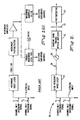
- Multichannel coherent transmission [reference 1 supra ], wavelength-division multiplexing [reference 2 supra ], and subcarrier multiplexing [reference 3 supra ] are known techniques for transmitting a number of independent information channels on a single optical fiber. Schematic representations of systems using each of these transmission techniques are shown in Fig. 1.
- the system of reference 3 as shown in Fig. 1 (c) comprises a sub-carrier-multiplexed optical transmission system including an optical transmitter comprising a high speed diode laser coupled to be modulated by a plurality of independent information channels carried on separate, appropriately spaced, carrier frequencies and having an output therefrom; an optical fibre coupled to said output, and an optical receiver including a photo detector.
- Table 1 summarizes the advantages and disadvantages of each technique.
- a principal object of this invention is to provide a new and improved subcarrier-multiplexed optical transmission system which has a number of important advantages compared to prior art multi-channel transmission systems.
- the notable advantages of the invention described herein are summarized in Table II. TABLE II ADVANTAGES OF SUBCARRIER-MULTIPLEXED OPTICAL TRANSMISSION SYSTEMS USING OPTICAL CHANNEL SELECTION ADVANTAGES OVER MULTICHANNEL COHERENT TRANSMISSION ADVANTAGES OVER WAVELENGTH DIVISION MULTIPLEXING ADVANTAGES OVER SUBCARRIER-MULTIPLEXING WITH ELECTRONIC CHANNEL SELECTION Does not require narrow-linewidth lasers.
- a subcarrier-multiplexed optical transmission system of the kind referred to above is characterised in that said optical receiver further includes a narrow-bandpass semiconductor laser optical amplifier, having an input and an output and having a gain bandwidth smaller than wavelength distances between adjacent ones of said carrier frequencies, and polarisation controlling means coupling said optical fibre to said input of the optical amplifier for maximising gain in said optical amplifier, said output of said optical amplifier being coupled to said photodetector.
- a narrow-bandpass semiconductor laser optical amplifier having an input and an output and having a gain bandwidth smaller than wavelength distances between adjacent ones of said carrier frequencies
- polarisation controlling means coupling said optical fibre to said input of the optical amplifier for maximising gain in said optical amplifier, said output of said optical amplifier being coupled to said photodetector.
- the optical amplifier may be a single-longitudinal-mode distributed feedback (DFB) semiconductor laser optical amplifier.
- the optical amplifier can be of the Fabry-Perot type, where the system further includes a blocking filter between the amplifier output and the photodetector.
- a subcarrier-multiplexed optical transmission system of the kind referred to above is characterised in that said high-speed diode laser has an optical carrier corresponding to an unmodulated longitudinal mode thereof, and that said optical receiver comprises a wide bandwidth, 'travelling wave', optical amplifier having an input coupled to said optical fiber, said amplifier having an output; a tunable narrow-band optical filter, coupled to said output of said amplifier, for rejecting the optical carrier corresponding to said unmodulated longitudinal mode of said transmitter laser; and a blocking filter between said narrow-band optical filter and said photodetector for preventing spurious signals from reaching said photodetector.
- a high-speed diode laser 21 is coupled to be modulated by a number of independent information channels carried on separate, appropriately spaced carrier frequencies.
- a Fabry-Perot or distributed feedback semiconductor laser optical amplifier 22 (such as taught in references 4, 5, supra ) is designed and biased to provide narrow gain passband sufficient to select any one of the sub-carrier-multiplexed information channels and reject the wavelengths corresponding to the laser longitudinal mode(s).
- the wavelength of the amplifier 22 gain peak can be tuned to any of the subcarrier channels by varying the amplifier base current and/or temperature, whereby the optical amplifier 22 acts as a frequency selective element in a subcarrier-multiplexed transmission system 20.
- Amplifier passband widths of less than 2 GHz have been demonstrated [reference 6 supra ], whereby several independent subcarriers can be accommodated by using a laser with a multigigahertz modulation bandwidth.
- Diode lasers with modulation bandwidths exceeding 18 GHz have been demonstrated [reference 7 supra ], and further improvements are expected to extend modulation bandwidths to greater than 20 GHz.
- the number of channels that can be transmitted, using a single subcarrier-multiplexed diode laser transmitter, increases with increasing diode laser modulation bandwidth and decreasing optical amplifier passband width.
- the optical amplifier 22 is designed to have a passband which is sufficiently narrow to reject the (unmodulated) laser longitudinal mode wavelengths, the signal incident on the photodetector 23 contains only baseband information. Unlike standard subcarrier- multiplexed transmission systems, a high speed photodetector is not needed and the required photodetector bandwidth is the same as that of a simple baseband intensity-modulated transmission system.
- the optical amplifier 22 can provide over 20 dB of gain, so the receiver sensitivity of the subcarrier-modulated system 20 described herein can approach that of a coherent communication system.
- the electrical input to the high frequency diode laser is provided by channel #1 baseband signal at a frequency f1, by channel #2 baseband signal at a frequency f2, etc.
- the output of the diode laser 21 is coupled via an optical fiber link 24, past a polarization controller 26, to the narrowband tunable optical amplifier 22.
- the output of the amplifier 22 is directed to the photodetector 23, via a blocking filter 27.
- a representative diagram of the optical emission spectra from the diode laser and the spectral characteristics of the optical components in the system 20 are shown in Fig. 3a, 3b, 3c and 3d. The function of each system component is detailed below:
- FIG. 4 A block diagram of the second embodiment of the subcarrier-multiplexed transmission system is shown in Fig. 4.
- the transmitter, polarization controller 26, photodetector 23 and receiver are of the same type as described above.
- a wide-bandwidth traveling wave optical amplifier 31 followed by a tunable narrowband optical filter 32 are substituted for the narrowbandwidth tunable optical amplifier 22 used in the first embodiment.
- a representative diagram of the optical emission spectra from the diode laser and the spectral characteristics of the optical components in the second novel system embodiment are shown in Figs. 5a, 5b, 5c, 5d and 5e. Descriptions of these components are given below.
Landscapes
- Engineering & Computer Science (AREA)
- Computer Networks & Wireless Communication (AREA)
- Signal Processing (AREA)
- Optical Communication System (AREA)
- Semiconductor Lasers (AREA)
Claims (4)
- Optisches Unterträger-Multiplex-Übertragungssystem mit einem optischen Sender, der einen Hochgeschwindigkeits-Diodenlaser (21), der verbunden ist, um durch eine Mehrzahl unabhängiger Informationskanäle moduliert zu werden, die auf getrennten, geeignet beabstandeten Trägerfrequenzen übertragen werden, und einen Ausgang umfaßt, an den ein Lichtleiter (24) angeschlossen ist, und einem optischen Empfänger mit einem Photodetektor (23), dadurch gekennzeichnet, daß der optische Empfänger weiter umfaßt einen optischen Schmalband-Halbleiter-Laserverstärker (22) mit einem Eingang und einem Ausgang und mit einer Verstärkungsbandbreite, die kleiner ist als die Wellenlängenabstände zwischen benachbarten Trägerfrequenzen, und eine Polarisations-Steuereinrichtung (26), die den Lichtleiter (24) mit dem Eingang des optischen Verstärkers verbindet, um die Verstärkung in dem optischen Verstärker (22) zu maximieren, wobei der Ausgang des optischen Verstärkers (22) mit dem Photodetektor (23) verbunden ist.
- System nach Anspruch 1, dadurch gekennzeichnet, daß der optische Verstärker (22) ein Fabry-Perot-Typ ist, und daß das System weiter
ein Sperrfilter (27) zwischen dem Ausgang des Verstärkers (22) und dem Photodetektor (23) umfaßt. - System nach Anspruch 1, dadurch gekennzeichnet, daß der optische Verstärker (22) ein einzelner optischer Halbleiter-Laserverstärker mit verteilter Rückkopplung (DFB) ist.
- Optisches Unterträger-Multiplex-übertragungssystem mit einem optischen Sender, der einen Hochgeschwindigkeits-Diodenlaser (21), der verbunden ist, um durch eine Mehrzahl unabhängiger Informationskanäle moduliert zu werden, die auf getrennten, geeignet beabstandeten Trägerfrequenzen übertragen werden, und einen Ausgang umfaßt, an den ein Lichtleiter (24) angeschlossen ist, und einem optischen Empfänger mit einem Photodetektor (23), dadurch gekennzeichnet, daß der Hochgeschwindigkeits-Diodenlaser einen optischen Träger hat, der einem unmodulierten Längsmode desselben entspricht, und daß der optische Empfänger einen optischen 'Wanderwellen'-Breitbandverstärker (31) mit einem mit dem Lichtleiter verbundenen Eingang und einem Ausgang; ein abstimmbares optisches Schmalbandfilter (32), das mit dem Ausgang des Verstärkers verbunden ist, zum Unterdrücken des optischen Trägers, der dem unmodulierten Längsmode des Senderlasers (21) entspricht; und ein Sperrfilter (27) zwischen dem optischen Schmalbandfilter und dem Photodetektor (23), um Störsignale daran zu hindern, den Photodetektor zu erreichen, umfaßt.
Applications Claiming Priority (2)
| Application Number | Priority Date | Filing Date | Title |
|---|---|---|---|
| US12681187A | 1987-11-30 | 1987-11-30 | |
| US126811 | 1987-11-30 |
Publications (3)
| Publication Number | Publication Date |
|---|---|
| EP0319242A2 EP0319242A2 (de) | 1989-06-07 |
| EP0319242A3 EP0319242A3 (en) | 1990-11-14 |
| EP0319242B1 true EP0319242B1 (de) | 1993-10-13 |
Family
ID=22426813
Family Applications (1)
| Application Number | Title | Priority Date | Filing Date |
|---|---|---|---|
| EP88311289A Expired - Lifetime EP0319242B1 (de) | 1987-11-30 | 1988-11-29 | Optische Übertragungssysteme mit mehrfach ausgenutzten Hilfsträgern unter Anwendung optischer Kanalauswahl |
Country Status (5)
| Country | Link |
|---|---|
| US (1) | US5537634A (de) |
| EP (1) | EP0319242B1 (de) |
| JP (1) | JPH022232A (de) |
| CA (1) | CA1330242C (de) |
| DE (1) | DE3884917T2 (de) |
Families Citing this family (27)
| Publication number | Priority date | Publication date | Assignee | Title |
|---|---|---|---|---|
| DE69019846T2 (de) * | 1989-03-09 | 1995-12-07 | Canon Kk | Optisches Übertragungssystem. |
| US5020049A (en) * | 1989-10-13 | 1991-05-28 | At&T Bell Laboratories | Optical sub-carrier multiplex television transmission system using a linear laser diode |
| US5077728A (en) * | 1989-12-20 | 1991-12-31 | At&T Bell Laboratories | Frequency division multiple access network |
| US5105295A (en) * | 1990-01-03 | 1992-04-14 | Gte Laboratories Incorporated | Four level FSK optical signal transmission with optical decoding and direct detection |
| NL9000149A (nl) * | 1990-01-22 | 1991-08-16 | Philips Nv | Coherent optische heterodyne transmissiesysteem. |
| US5267074A (en) * | 1990-01-22 | 1993-11-30 | U.S. Philips Corporation | Coherent optical heterodyne transmission system |
| EP0772312A3 (de) * | 1990-09-14 | 1997-09-03 | Fujitsu Ltd | Optisches Kommunikationssystem mit gemultiplexten Unterträgern |
| US5627668A (en) * | 1992-02-10 | 1997-05-06 | Gte Laboratories Incorporated | Subcarrier-multiplexed optical transmission systems using optical channel selection |
| EP0558089B1 (de) * | 1992-02-28 | 2002-06-05 | Hitachi, Ltd. | Optische integrierte Halbleitervorrichtung und Verfahren zur Herstellung und Verwendung in einem Lichtempfänger |
| US6191878B1 (en) * | 1994-04-01 | 2001-02-20 | Brett Spivey | Optical communication system |
| DE19628321C1 (de) * | 1996-07-13 | 1998-01-15 | Univ Dresden Tech | Multiplexverfahren für zwei Subcarrier und Anordnung hierzu |
| US6115155A (en) * | 1996-10-29 | 2000-09-05 | Chorum Technologies Inc. | System for dealing with faults in an optical link |
| JPH10164020A (ja) * | 1996-11-29 | 1998-06-19 | Nec Corp | 光波長多重中継伝送システムおよびその光s/n比等化方法 |
| DE19822616A1 (de) | 1998-05-20 | 1999-11-25 | Sel Alcatel Ag | Lichtquelle sowie Verfahren für die Übertragung von spektralkodierten Daten |
| US6496549B1 (en) * | 1999-07-13 | 2002-12-17 | Hewlett-Packard Company | Method and apparatus for demodulating amplitude-shift keyed data signals |
| US6624000B1 (en) * | 1999-09-02 | 2003-09-23 | Agility Communications, Inc. | Method for making a monolithic wavelength converter assembly |
| US6879640B1 (en) * | 1999-10-20 | 2005-04-12 | Broadcom Corporation | Method, apparatus and system for high-speed transmission on fiber optic channel |
| US6803604B2 (en) * | 2001-03-13 | 2004-10-12 | Ricoh Company, Ltd. | Semiconductor optical modulator, an optical amplifier and an integrated semiconductor light-emitting device |
| EP1300968A1 (de) * | 2001-10-03 | 2003-04-09 | Alcatel | Vorrichtung zum demultiplexen von optischen Signalen mit RZ-Format |
| US7061618B2 (en) * | 2003-10-17 | 2006-06-13 | Axsun Technologies, Inc. | Integrated spectroscopy system |
| JP4872003B2 (ja) * | 2008-02-22 | 2012-02-08 | 日本電信電話株式会社 | 光ofdm受信器および光伝送システムおよびサブキャリア分離回路およびサブキャリア分離方法 |
| US7852152B2 (en) * | 2008-08-28 | 2010-12-14 | Menara Networks | Nth order tunable low-pass continuous time filter for fiber optic receivers |
| US8526472B2 (en) | 2009-09-03 | 2013-09-03 | Axsun Technologies, Inc. | ASE swept source with self-tracking filter for OCT medical imaging |
| US8670129B2 (en) | 2009-09-03 | 2014-03-11 | Axsun Technologies, Inc. | Filtered ASE swept source for OCT medical imaging |
| EP2867918A1 (de) * | 2012-06-26 | 2015-05-06 | Kla-Tencor Corporation | Nahfeld-metrologie |
| US9419719B2 (en) * | 2014-03-19 | 2016-08-16 | Huawei Technologies Co., Ltd. | Transmitter apparatus and method |
| US11050487B2 (en) * | 2019-07-15 | 2021-06-29 | Huawei Technologies Co., Ltd. | Method and apparatus for laser frequency control |
Family Cites Families (6)
| Publication number | Priority date | Publication date | Assignee | Title |
|---|---|---|---|---|
| US4228349A (en) * | 1978-08-28 | 1980-10-14 | Rca Corporation | III-V Direct-bandgap semiconductor optical filter |
| NL7900668A (nl) * | 1978-11-08 | 1980-05-12 | Philips Nv | Inrichting voor het opwekken of versterken van coheren- te electromagnetische straling, en werkwijze voor het vervaardigen van de inrichting. |
| JPS58111449A (ja) * | 1981-12-24 | 1983-07-02 | Fujitsu Ten Ltd | 多重光伝送方式 |
| JPS58197930A (ja) * | 1982-05-14 | 1983-11-17 | Nippon Telegr & Teleph Corp <Ntt> | 光分波器 |
| US4592043A (en) * | 1983-07-08 | 1986-05-27 | At&T Bell Laboratories | Wavelength division multiplexing optical communications systems |
| GB2162400B (en) * | 1984-07-11 | 1988-01-06 | Matsushita Electric Industrial Co Ltd | Analog optical transmission system |
-
1988
- 1988-11-23 CA CA000583832A patent/CA1330242C/en not_active Expired - Fee Related
- 1988-11-29 EP EP88311289A patent/EP0319242B1/de not_active Expired - Lifetime
- 1988-11-29 DE DE88311289T patent/DE3884917T2/de not_active Expired - Fee Related
- 1988-11-29 JP JP63299770A patent/JPH022232A/ja active Pending
-
1992
- 1992-02-10 US US07/833,574 patent/US5537634A/en not_active Expired - Lifetime
Also Published As
| Publication number | Publication date |
|---|---|
| DE3884917T2 (de) | 1994-02-03 |
| US5537634A (en) | 1996-07-16 |
| EP0319242A3 (en) | 1990-11-14 |
| JPH022232A (ja) | 1990-01-08 |
| CA1330242C (en) | 1994-06-14 |
| EP0319242A2 (de) | 1989-06-07 |
| DE3884917D1 (de) | 1993-11-18 |
Similar Documents
| Publication | Publication Date | Title |
|---|---|---|
| US5537634A (en) | Subcarrier-multiplexed optical transmission systems using optical channel selection | |
| US5369516A (en) | Optical communication network system and communication method using the same | |
| EP2507877B1 (de) | Verfahren und vorrichtung zur wellenlängestabilisierung und -verrigelung für wellenlängenmultiplex sender | |
| JP3303515B2 (ja) | 光通信方式及びそれを用いた光通信システム | |
| Hill | Wavelength domain optical network techniques | |
| CA2562790C (en) | Coolerless and floating wavelength grid photonic integrated circuits (pics) for wdm transmission networks | |
| JP3226067B2 (ja) | 光通信方法及び光通信システム | |
| EP0682390B1 (de) | Vorrichtung und Verfahren zur Steuerung einer polarisationsselektiver Lichtquelle, und optisches Kommunikationssystem unter Verwendung desselben | |
| CA2124708C (en) | Spectrum-sliced fiber amplifier light source for multi-channel wavelength-division-multiplexed applications | |
| US6134250A (en) | Wavelength-selectable fiber ring laser | |
| EP0562518A2 (de) | Optisches Gerät und Methode unter Benutzung desselben, das die Änderung einer über beiden Enden eines verstarkenden Bereichs abfallender Spannung ausnutzt | |
| US6381047B1 (en) | Passive optical network using a fabry-perot laser as a multiwavelength source | |
| Holloway et al. | Multiwavelength source for spectrum-sliced WDM access networks and LAN's | |
| US5627668A (en) | Subcarrier-multiplexed optical transmission systems using optical channel selection | |
| US10243327B2 (en) | Optical source | |
| CA2310199A1 (en) | Multi-wavelength lasers | |
| EP3840138A1 (de) | Dwdm-intra-resonator-laservorrichtung | |
| Monnard et al. | Direct modulation of a multifrequency laser up to 16 x 622 Mb/s | |
| Liou et al. | Monolithically integrated semiconductor LED-amplifier for applications as transceivers in fiber access systems | |
| US6678480B1 (en) | Optical transmitter and optical communication system | |
| US5847855A (en) | Integrated coherent transceiver | |
| US20040208566A1 (en) | Coarse WDM system of large capacity with un-cooled lasers | |
| JP2927879B2 (ja) | 波長多重光通信ネットワーク及びそこで用いる通信方法 | |
| Numai | Semiconductor wavelength tunable optical filters | |
| JPH08139401A (ja) | 光伝送装置の変調方式及びこれを用いた光通信方式 |
Legal Events
| Date | Code | Title | Description |
|---|---|---|---|
| PUAI | Public reference made under article 153(3) epc to a published international application that has entered the european phase |
Free format text: ORIGINAL CODE: 0009012 |
|
| AK | Designated contracting states |
Kind code of ref document: A2 Designated state(s): BE DE FR GB IT |
|
| PUAL | Search report despatched |
Free format text: ORIGINAL CODE: 0009013 |
|
| AK | Designated contracting states |
Kind code of ref document: A3 Designated state(s): BE DE FR GB IT |
|
| RHK1 | Main classification (correction) |
Ipc: H04J 14/02 |
|
| 17P | Request for examination filed |
Effective date: 19901231 |
|
| 17Q | First examination report despatched |
Effective date: 19920213 |
|
| GRAA | (expected) grant |
Free format text: ORIGINAL CODE: 0009210 |
|
| AK | Designated contracting states |
Kind code of ref document: B1 Designated state(s): BE DE FR GB IT |
|
| PGFP | Annual fee paid to national office [announced via postgrant information from national office to epo] |
Ref country code: BE Payment date: 19931026 Year of fee payment: 6 |
|
| ET | Fr: translation filed | ||
| PGFP | Annual fee paid to national office [announced via postgrant information from national office to epo] |
Ref country code: FR Payment date: 19931105 Year of fee payment: 6 |
|
| REF | Corresponds to: |
Ref document number: 3884917 Country of ref document: DE Date of ref document: 19931118 |
|
| PGFP | Annual fee paid to national office [announced via postgrant information from national office to epo] |
Ref country code: GB Payment date: 19931125 Year of fee payment: 6 |
|
| ITF | It: translation for a ep patent filed | ||
| PGFP | Annual fee paid to national office [announced via postgrant information from national office to epo] |
Ref country code: DE Payment date: 19931230 Year of fee payment: 6 |
|
| PLBE | No opposition filed within time limit |
Free format text: ORIGINAL CODE: 0009261 |
|
| STAA | Information on the status of an ep patent application or granted ep patent |
Free format text: STATUS: NO OPPOSITION FILED WITHIN TIME LIMIT |
|
| 26N | No opposition filed | ||
| PG25 | Lapsed in a contracting state [announced via postgrant information from national office to epo] |
Ref country code: GB Effective date: 19941129 |
|
| PG25 | Lapsed in a contracting state [announced via postgrant information from national office to epo] |
Ref country code: BE Effective date: 19941130 |
|
| BERE | Be: lapsed |
Owner name: GTE LABORATORIES INC. Effective date: 19941130 |
|
| GBPC | Gb: european patent ceased through non-payment of renewal fee |
Effective date: 19941129 |
|
| PG25 | Lapsed in a contracting state [announced via postgrant information from national office to epo] |
Ref country code: FR Effective date: 19950731 |
|
| PG25 | Lapsed in a contracting state [announced via postgrant information from national office to epo] |
Ref country code: DE Effective date: 19950801 |
|
| REG | Reference to a national code |
Ref country code: FR Ref legal event code: ST |
|
| PG25 | Lapsed in a contracting state [announced via postgrant information from national office to epo] |
Ref country code: IT Free format text: LAPSE BECAUSE OF NON-PAYMENT OF DUE FEES;WARNING: LAPSES OF ITALIAN PATENTS WITH EFFECTIVE DATE BEFORE 2007 MAY HAVE OCCURRED AT ANY TIME BEFORE 2007. THE CORRECT EFFECTIVE DATE MAY BE DIFFERENT FROM THE ONE RECORDED. Effective date: 20051129 |