EP0319266B1 - Système d'alarme d'incendie - Google Patents
Système d'alarme d'incendie Download PDFInfo
- Publication number
- EP0319266B1 EP0319266B1 EP88311339A EP88311339A EP0319266B1 EP 0319266 B1 EP0319266 B1 EP 0319266B1 EP 88311339 A EP88311339 A EP 88311339A EP 88311339 A EP88311339 A EP 88311339A EP 0319266 B1 EP0319266 B1 EP 0319266B1
- Authority
- EP
- European Patent Office
- Prior art keywords
- fire
- detectors
- detector
- master
- circuit
- Prior art date
- Legal status (The legal status is an assumption and is not a legal conclusion. Google has not performed a legal analysis and makes no representation as to the accuracy of the status listed.)
- Expired - Lifetime
Links
Images



Classifications
-
- G—PHYSICS
- G08—SIGNALLING
- G08B—SIGNALLING SYSTEMS, e.g. PERSONAL CALLING SYSTEMS; ORDER TELEGRAPHS; ALARM SYSTEMS
- G08B26/00—Alarm systems in which substations are interrogated in succession by a central station
- G08B26/001—Alarm systems in which substations are interrogated in succession by a central station with individual interrogation of substations connected in parallel
- G08B26/002—Alarm systems in which substations are interrogated in succession by a central station with individual interrogation of substations connected in parallel only replying the state of the sensor
-
- G—PHYSICS
- G08—SIGNALLING
- G08B—SIGNALLING SYSTEMS, e.g. PERSONAL CALLING SYSTEMS; ORDER TELEGRAPHS; ALARM SYSTEMS
- G08B25/00—Alarm systems in which the location of the alarm condition is signalled to a central station, e.g. fire or police telegraphic systems
- G08B25/01—Alarm systems in which the location of the alarm condition is signalled to a central station, e.g. fire or police telegraphic systems characterised by the transmission medium
- G08B25/04—Alarm systems in which the location of the alarm condition is signalled to a central station, e.g. fire or police telegraphic systems characterised by the transmission medium using a single signalling line, e.g. in a closed loop
Definitions
- the present invention relates to a fire alarm system including a plurality of fire detectors connected to power supply and signal lines connected to a central receiving unit (receiver) whereby when a fire breaks out, the location of the fire is discriminated by the receiver in accordance with the specified address of any detector that has given an alarm.
- a central receiving unit receiver
- a large-scale fire detecting system covering a wide area under surveillance
- its construction is such that a plurality of repeaters are connected to a main circuit extending from a receiver and a plurality of fire detectors are connected to a branch circuit extending from each of the repeaters.
- US 3927404 discloses a communication system (e.g. a fire alarm system) comprising a central unit 20 connected to "Zone Status Monitors" 32 by means of a two-wire loop (see Figure 1).
- the loop carries data and power, and the zone status monitors transmit signals along the loop to the central unit 20 according to whether an alarm condition is detected.
- Address signals are generated by the central unit 20.
- the central control 20 communicates with a number of area control panels, each of which is connected to a number of monitors, and each of which is associated with an address pulse generator and which addresses its respective monitors.
- this system is expanded by having a number of address pulse generators for every area control panel.
- a fire alarm system comprising a central receiving unit, a pair of power supply and signal main lines connected to said central receiving unit and a plurality of master fire detectors connected to said power supply and signal main lines and each including address setting means and transmission means responsive to the detection of a fire by said master detector for transmitting a fire detection signal and an address signal assigned to each master fire detector to said central receiving unit, said fire alarm system further comprising one or more unaddressable slave fire detectors connected in parallel to each master fire detector whereby the fire detectors are arranged in a plurality of groups each corresponding to a respective area under surveillance and comprising a master fire detector and one or more slave fire detectors connected thereto, whereby the detection of a fire by one or more of the salve fire detectors results in the transmission of a fire detection signal and the address signal of the associated master fire detector by the associated transmission means to the said central receiving unit, characterised in that each fire detector includes self-holding switching means responsive to the detection of a fire so as to be turned on
- each of the group master detectors includes a mounting base and fire detecting means detachably mounted on the base, and the transmitting means is disposed on the mounting base.
- a terminal circuit element is connected to the group master detector of each group to supply a small steady-state monitor current to a power supply and signal local lines connecting the group master detector and the slave detector or detectors, and also the group master detector includes disconnection detecting means for generating a disconnection signal when the steady-state monitor current becomes smaller than given value.
- Each of the fire detectors should preferably be of the type including pulse driving means for periodically turning on the switching means upon the detection of a fire, and it should more preferably be designed such that the central receiving unit includes control means for determining the number of the master detectors which have given the alarm so as to deliver a control signal or signals designating the specified addresses of the unalarming master detectors to the power supply and signal main lines when the number of the alarming master detectors exceeds a predetermined number and that each of the master detectors includes current limit changeover means for changing over the limited current value of its own current limiting means to a lower value than the constant current value when the control signal from the central receiving unit is discriminated according to its specified address by the transmission means.
- both the master detector and the salve detector are provided respectively with an alarm indicating light-emitting diode which can be turned on by its own alarm current, whereby emitting at a scene may be observed visually.
- Each of these addressable detectors is a group master detector and one or a plurality of salve detectors, i.e. unaddressable detectors each thereof having no specified address signal of its own and serving only the function of transmitting a fire detection signal to the master detector are made dependent on the master detector.
- the plurality of fire detectors installed within the same area under surveillance comprise a single addressable master detector (group master detector) and one or more dependent unaddressable slave detectors which are formed into a group.
- group master detector the fire stricken area discriminating and indicating function of the central receiving unit can be simplified with the resulting reduction in the equipment cost and the wide use of systems having the function of discriminating and indicating the location of a fire can be made more realistic even in the case of equipment which are middle and small in scale.
- Each of the addressable detectors transmits its own detection of a fire and the detection of a fire by each of one or more unaddressable detectors (slave detectors) dependent on itself, along with its specified address signal, to the central receiving unit.
- the central receiving unit monitors the number of the alarming detectors within the same circuit so that when it exceeds a predetermined number, the central receiving unit sends to the circuit control signals each designating the address of one of the unalarming master detectors on the circuit.
- Each of the unalarming master detectors takes in the control signal having the address corresponding to the address of its own so that the limited current value by the current limiting means of its own is changed over for example to a current value lower than the steady-state monitor current value.
- the line currents between them and the central receiving unit are practically increased no longer and the net line current corresponding to the number of the previous alarming master detectors is maintained.
- the voltage drop due to the line resistance of the power supply and signal main lines between the central receiving unit and the master detectors is increased no longer and the reduction in the supply voltage to the detectors is suppressed, thereby ensuring the transmission of information between the central receiving unit and the master detectors.
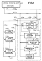
- Fig. 1 is block diagram showing a first embodiment of the present invention.
- Fig. 2 is a block diagram showing a second embodiment of the invention.
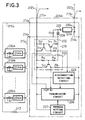
- Fig. 3 is a circuit diagram showing an example of one of the master detectors in the second embodiment and its attendant circuit construction.
- Fig. 4 is circuit diagram showing an example of the construction of the fire detecting means in the circuitry of Fig. 3.
- Fig. 5 is a timing chart for explaining the operation of the circuitry in Fig. 3.
- a receiver 101 forms a central receiving unit which functions so that when the fire detection signal from a detector installed in an area under surveillance is received, the address signal sent simultaneously from the detector is received and decoded to give a fire alarm and also to discriminate and indicate the fire stricken area.
- power supply and signal main lines 102a and 102b Connected to the receiver 101 are power supply and signal main lines 102a and 102b forming a main circuit extending to areas under surveillance, and connected in parallel with the main circuit 102a, 102b are a plurality of master detectors (addressable detectors) 103 which are arranged one for each area under surveillance.
- the master detector 103 includes a mounting base 130a for attachment to a ceiling or the like and a detector proper 130b adapted to be detachably mounted on the base 130a, and power supply and signal local lines 115a and 115b forming a local circuit extending to the same area under surveillance are respectively connected to local connection terminals 114a and 114b provided on the base 130a.
- a plurality of slave detectors 116a, 116b, ... 116n are connected in parallel with the local circuit 115a, 115b and a terminal resistor 117 for disconnection detecting purposes is connected to the terminal end of the local circuit.
- the detector proper 130b includes suitable fire detecting means 104 such as a photoelectric smoke detecting mechanism or ionization smoke detecting mechanism and the mounting base 130a includes fit terminals 119a, 119b and 120 for removably attaching and electrically connecting the fire detecting means 104, a current detecting circuit 105, a disconnection detecting circuit 123, a transmission circuit 106 and an address setting circuit 107.
- suitable fire detecting means 104 such as a photoelectric smoke detecting mechanism or ionization smoke detecting mechanism
- the mounting base 130a includes fit terminals 119a, 119b and 120 for removably attaching and electrically connecting the fire detecting means 104, a current detecting circuit 105, a disconnection detecting circuit 123, a transmission circuit 106 and an address setting circuit 107.
- the current detecting circuit 105 receives not only the detection output (current output) of its own fire detecting means 104 mounted on the detector proper 130b but also the detection outputs (current outputs) of the plurality of slave detectors 116a, 116b, ... 116n from the local circuit 115a, 115b through the local connection terminals 114a and 114b, so that the alarm current caused by the detection of a fire by its own fire detecting means 104 or the detection of a fire by any of the slave detectors 116a, 116b, ... 116n is detected by the current detecting circuit 105 whose current detection output (fire detection output) is in turn applied to the transmission circuit 106.
- the mounting base 130a is also provided with connecting terminals 113a and 113b for connection with the main circuit (102a, 102b).
- One of the terminals of the detector proper 130b including the fire detecting means 104 is mechanically fitted so as to provide an electric connection between the fit terminals 119a and 119b which are separately disposed on the power supply line on the positive side (the main circuit 102a side) of the mounting base 130a and the other terminal of the detector proper 130b is electrically and mechanically connected to the connection terminal 120 which is also provided on the mounting base 130a.
- the present embodiment is constructed such that the slave detectors 116a, 116b, ... 116n are in dependent relation with the master detector 103 to allow the slave detectors 116a, 116b, ... 116n to become effective only when the master detector 103 is functioning properly.
- the disconnection detecting circuit 123 receives a small disconnection monitor current flowing through the terminal resistor 117 in the local circuit 115a, 115b to which the slave detectors 116a, 116b, ... 116n are connected and thus a disconnection detection output is applied to the transmission circuit 106 when the disconnection monitor current is interrupted.
- a specified address signal is established for the transmission circuit 106 by the address setting circuit 107 so that when a current detection output or fire detection output is received from the current detection circuit 105, an alarm signal including the fire detection information and the address information is transmitted to the receiver 101, whereas when a disconnection detection output is received from the disconnection detecting circuit 123, an output signal including the disconnection detection information and the address information is transmitted to the receiver 101 in response to the call by means of the polling function of the receiver 101.
- the frame structure of the transmission signal sent to the receiver 101 from the transmission circuit 106 includes a start flag, address information, fire information bit, disconnection information bit and end flag.
- the frame structure is not limited to this structure any suitable frame structure may be employed provided that it includes fire detection information and address information when a fire is detected and it includes address information and disconnection detection information when a disconnection is detected.
- the master detector 103 and the slave detectors 116a, 116b, ... 116n are installed in the same area under surveillance so that when a fire breaks out in this area thus causing for example the fire detecting means 104 in the detector proper 130b of the master detector 103 to detect the fire, the fire detecting means 104 comes into operation and an alarm current flows to the current detecting circuit 105 provided on the mounting base 130b, thus causing the current detecting circuit 105 to apply a current detection output or fire detection output to the transmission circuit 106.
- the transmission circuit 106 transmits the fire detection information as well as the address information set by the address setting circuit 107 in a signal form of a given data frame structure to the receiver 101 through the main circuit 102a, 102b in response to the polling from the receiver 101 so that upon receiving the signal from the master detector 103, the receiver 101 discriminates the installation area of the alarming master detector in accordance with the address information in the signal to indicate the fire stricken area.
- any of the slave detectors 116a, 116b, ... 116n e.g., the slave detector 116a detects the fire
- an alarm current is supplied through the circuit 115a, 115b to the current detecting circuit 105 disposed on the mounting base 130a of the master detector 103 so that a detection output is applied from the current detecting circuit 105 to the transmission circuit 106 which in turn transmits data of the given data frame structure including the address information and fire detection information to the receiver 101.
- the receiver 101 decodes the address information to discriminate and indicate the fire stricken area.
- the first alarm system has a discriminating and indicating function, it ensures the use of a considerably reduced number of addressable detectors having an address transmission function and this greatly simplifies the equipment construction.
- FIG. 2 there is illustrated a second embodiment of the invention which is so designed that with a plurality of master detectors connected to the same main circuit, when the number of the alarming detectors exceeds a certain upper limit, an address-designated control signal is transmitted from the receiver side to limit the current flowing in the fire detecting means of each of the master detectors which have generated no alarm as yet.
- numeral 201 designates a receiver forming a central receiving unit and a plurality of addressable master detectors 203A, 203B, ... 203N respectively corresponding to the respective areas under suveillance are connected to power supply and signal main lines 202a and 202b forming a main circuit connected to the receiver 201. Also, a plurality of unaddressable slave detectors 216A, 216B ... 216N are connected to each of the addressable detectors.
- the receiver 201 includes a receiving circuit 209 and a transmitting circuit 212 which are connected to the main circuit 202a, 202b, a control circuit 210 and an alarm indicator 211, so that the transmission signal including fire information and address information and transmitted in response to the detection of a fire by any of the addressable detectors 203A, 203B, ... 203N is received and decoded by the receiving circuit 209 and a reception output is applied to the control circuit 210.
- the control circuit 210 decodes the fire detection information and the address information to cause the alarm indicator 211 to generate a fire alarm, indicate the fire alarm and indicate the fire stricken area in accordance with the address information.
- the control circuit 210 determines that the number of the alarming master detectors has reached a predetermined upper limit number so that the transmitting circuit 212 transmits to the main lines 202a, 202b an address-designated current limiting control signal for each of the unalarming master detectors connected to the main circuit.
- This current limiting control signal transmitting function of the control circuit 210 is such that when the alarms from a total of two addressable detectors, for example, are detected as the result of the information sent from a certain main circuit, current limiting control signals designating the specified addresses of all the other unalarming master detectors connected to the same main circuit are sent to the main circuit.
- Fig. 3 shows in partial block diagram form the circuit construction of the addressable detector 203A which is one of those shown in Fig. 2.
- the single master detector and the plurality of slave detectors are installed in the same area under surveillance to form a group and the address signal of the master detector represents the group.
- the main circuit lines 202a, 202b from the receiver 201 are respectively connected to connection terminals 213a and 213b of the addressable master detector 203A, and the slave detectors 216A to 216N comprising the ordinary detectors having no specified address signals are connected in parallel with a local circuit formed by power supply and signal local lines 215a and 215b extending from local connection terminals 214a and 214b of the master detector 203A.
- a disconnection detecting terminal resistor 217 is connected to the terminal end of the local circuit 215a, 215b.
- Fire detecting means 204 and 204A to 204N are respectively detachably incorporated in the master detector 203A and the unaddressable slave detectors 216A to 216N, and each of the fire detecting means comprises for example a combination of a fire detection circuit 221 utilizing a photoelectric-type or ionization-type smoke detecting mechanism and a thyristor 222 serving as a switching element as shown in Fig. 4.
- the fire detection circuit 221 is constructed so that intermittent light pulses are repeatedly applied within the detection chamber of its fire detecting mechanism and the scattered light due to the smoke entering the chamber is detected by a photosensitive element to produce a fire detection output for turning on the thyristor 222 when the photosensitive output attains a given level.
- the fire detection circuit 221 is constructed so as to generate a fire detection output intermittently upon the detection of a fire.
- the fire detection output is applied to the gate electrode of the thyristor 222 so that the thyristor 222 is triggered into a conduction state by the output of the fire detection circuit 221 to supply an alarm current to the local circuit 215a, 215b.
- the thyristor 222 is turned on and held in this state by itself, the alarm current flows continuously, whereas when no self-holding is provided, the alarm current flows intermittently in response to the pulses.
- the addressable master detector 203A includes a current detecting circuit 205 for detecting the alarm current caused by the detection of a fire by the fire detection circuit 204, a disconnection detecting circuit 223 for applying a disconnection detection output to a transmission circuit 206 upon the interruption of a weak monitor current flowing to the local circuit 215a, 215b through the terminal resistor 217, the transmission circuit 206 whereby fire detection information is transmitted, along with the specified address signal set by an address setting circuit 207, to the receiver 201 when the current detecting circuit 205 generates a detection output and disconnection detection information and the specified address signal are transmitted to the receiver 201 when the disconnection detecting circuit 223 generates a detection output, and a current limiting circuit 218 inserted between the fire detecting means 204 and the current detecting circuit 205.
- an alarm indicating light-emitting diode 208 which is turned on by the alarm current and also connected in parallel with the light-emitting diode 208 is a resistor R7 for preventing the light-emitting diode 208 from being turned on during the steady-state monitoring in the non-firing condition and protecting it. Also, a similar alarm indicating circuit is provided for each of the slave detectors 216A to 216N.
- the current limiting circuit 218 has a current regulating function whereby the alarm current generated upon the detection of a fire is limited to a constant current value of the order which is sufficient for the thyristor 222 in the fire detecting means 204 (or any of 204A to 204N) of the alarming detector to self-hold it in the conductive state and also sufficient for turning on the light-emitting diode 208 for indicating the alarm of the alarming detector, e.g., 6mA.
- the alarm indicating light-emitting diode 208, the current limiting circuit 218, the current detecting circuit 205, the disconnection detecting circuit 223, the transmission circuit 206 and the address setting circuit 207 of the master detector 203A are incorporated in the mounting base for mounting the master detector on a ceiling or the like and the fire detecting means 204 is disposed on the detector proper which is detachably mounted on the mounting base.
- the fire detecting means 204 disposed on the detector proper is detachably connected to positive-side separated fit terminals 219a and 219b and a negative-side fit terminal 220 which are disposed on the mounting base.
- the local lines 215a, 215b to which the plurality of slave detectors are connected are respectively connected to the local connection terminals 214a and 214b which are disposed on the mounting base of the master detector 203A.
- the connection terminal 214a is connected to the positive-side power line on the fit terminals 219b side and the other connection terminal 214b is connected between the alarm indicating light-emitting diode 208 and the current limiting circuit 218.
- the current limiting circuit 218 disposed in the master detector 203A forms a current regulating circuit with transistors T r1 and T r2 and resistors R1, R2 and R3. With the current limiting circuit 218, in the steady-state monitoring condition the transistor T r1 is turned on and the transistor T r2 is turned off so that a steady-state monitor current of about 0.7mA, for example, is supplied through the transistor T r1 .
- the collector current of the transistor T r1 is controlled by the transistor T r2 to establish a current regulating operating condition.
- the current detecting circuit 205 arranged to follow the current limiting circuit 218 is composed of a voltage comparator including a transistor T r3 and resistors R4 and R5 so that a voltage input corresponding to the value of the previously mentioned limited current flowing in the current limiting circuit 218 is divided by the resistors R4 and R5 and applied to the base electrode of the transistor T r3 .
- the impedance of the fire detecting means 204 (or 204A to 204N) is large enough as compared with that of the current limiting circuit 218 so that the value of the limited current flowing in the current limiting circuit 218 is reduced for example to 0.7mA and thus the base input voltage of the transistor T r3 is correspondingly reduced and the transistor T r3 is turned off.
- the impedance of the fire detecting means 204 (or 204A to 204N) is made small enough as compared with that of the current limiting circuit 218 upon the detection of fire, the current limiting circuit 218 comes into the current regulating operation and the alarm current flowing through the transistor T r1 is limited to a constant value, e.g., 6mA.
- the base input voltage of the transistor T r3 is increased as compared with that in the previous steady-state monitoring condition and thus the transistor T r3 is turned on.
- the collector output of the transistor T r3 of the current detecting circuit 205 is applied to the input terminal IN of the transmission circuit 206.
- the input terminal IN is set to an H level through the resistor R6 and the input terminal IN is pulled down to an L level in response to the turning on of the transistor T r3 upon the detection of a fire.
- the transmission circuit 206 sends the fire detection information as well as the specified address information set by the address setting circuit 207 toward the receiver 201.
- the transmission circuit 206 receives the current limiting control signal supplied from the receiver 201 shown in Fig. 2 so that when the designated address of the received control signal coincides with its own specified address, a control output for limited current value changeover purposes is generated and its output terminal OUT is set to the L level.
- the output terminal OUT of the transmission circuit 206 is connected to the collector electrode of the transistor T r2 included in the current limiting circuit 218.
- the current limiting circuit 218 Since the output terminal OUT of the transmission circuit 206 is in the high impedance condition of the H level in the steady-state monitoring condition, the current limiting circuit 218 performs the previously mentioned current limiting operation without any difficulty. On the other hand, when the transmission circuit 206 receives from the receiver 201 a control signal whose address content designates itself, the transmission circuit 206 sets its output terminal OUT to the L level. When this occurs, the transistor T r1 of the current limiting circuit 218 is caused to turn off.
- the resistance value of the resistor R3 is preliminarily selected sufficiently large as compared with the resistor R1 so that when the transistor T r1 is forced to go off, the current limiting circuit 218 is changed over to a limiting condition where it supplies only a monitor current of a value, e.g., 0.5mA which is lower than the value of the steady-state monitor current such as the previously mention 0.7mA.
- the detection of a fire is made by the addressable master detector 203A at a time t1 as shown in the timing chart of Fig. 5, since the master detector 203A includes the current limiting circuit 218 as shown in Fig. 3, the alarm current from the fire detecting means 204 is limited to 6mA by the current limiting circuit 218 and simultaneously a transmission signal including the fire detection information and the specified address information is transmitted to the receiver 201 from the transmission circuit 206 of the master detector 203.
- This transmission signal is received by the receiving circuit 209 of the receiver 201 so that the control circuit 210 discriminates the fire detection information and the address information and the alarm indicator 211 indicates the alarm and the alarming detector address.
- control circuit 210 of the receiver 201 is preset so that an address-designated current limiting control signal sent to each of the other unalarming master detectors when the number of alarming detectors becomes 2, control signals designating the addresses of the other unalarming master detectors 203C to 203N excluding the master detectors 203A and 203B which have already alarmed are sent from the receiver 201.
- the transmission circuit 206 discriminates the current limiting control signal from the receiver 201 so that an L level output is generated at the output terminal of the transmission circuit 206 and the transistor T r1 of the current limiting circuit 218 is caused to turn off.
- the current steady-state monitor current of 0.7mA is changed over to a lower monitor current of 0.5mA.
- the line current flowing into the main circuit 202a, 202b from the receiver 201 is maintained at the alarm current value attained when the number of the alarming detectors reached the preset number of 2 and the line current is no longer increased.
- the amount of the voltage drop due to the line resistance is not increased thereby ensuring the subsequent transmission of information between the alarming and unalarming detectors and the receiver.
- the limited current of the current limiting circuit is changed over to the lower value of 0.5mA at the time t2 in Fig. 5 as mentioned previously and then the detection of a fire is made by the detector 203N at the time t n .
- the fire detecting circuit 221 of the fire detecting means 204 generates an intermittent fire detection output as mentioned in connection with Fig. 4.
- the thyristor 222 of the master detector 203N When the thyristor 222 of the master detector 203N is triggered by the intermittent fire detection output, the thyristor 222 cannot be self-held in the ON state by the previously mentioned limited current value of 0.5mA and it performs the same intermittent on-off operation as the fire detection output. As a result, during the time that the thyristor 222 is turned on, the transistor T r3 is turned on and off in the current detecting circuit 205 of the master detector 203N to which the thyristor 222 belongs and the input terminal IN of the transmission circuit 206 is caused to go to the L level intermittently.
- ⁇ T2 represents the L-level pulling time of the input terminal IN required for the transmission operation of the transmission circuit 206
- ⁇ T2 represents the L-level pulling time of the input terminal IN required for the transmission operation of the transmission circuit 206
- ⁇ T1 the duration time (pulse width) ⁇ T1 of the fire detection output
- the alarm indicator is primarily utilized for the purpose of confirming the actuated detector by the guard arriving at the alarming area after a fire alarm has been given by the receiver 201 so that while it is necessary to turn on the alarm indicating LEDs for up to about the second alarm, to turn on the alarm indicating LEDs for the third alarm on does not have much significance from the standpoint of confirming the scene of fire and practically no problem is caused in this respect.
- the receiver 201 detects the alarms from two of the detectors so as to send a current limiting control signal to each of the remaining unalarming detectors
- the number of alarming detectors for starting the transmission of current limiting control signals may be suitably determined as occasion demands.
Landscapes
- Business, Economics & Management (AREA)
- Emergency Management (AREA)
- Physics & Mathematics (AREA)
- General Physics & Mathematics (AREA)
- Fire Alarms (AREA)
- Alarm Systems (AREA)
Claims (5)
- Un système d'alarme contre l'incendie comprenant une unité réceptrice centrale 201, une paire de lignes (202a, 202b) qui sont la ligne d'alimentation et la ligne principale de signaux, reliées à ladite unité centrale de réception (201) et une série de détecteurs d'incendie maîtres (203) qui sont reliés auxdites lignes d'alimentation et de signaux (202a, 202b), et incluent chacun un moyen de réglage (207) d'adresse et un moyen de transmission (206) qui répondent à la détection d'un incendie par ledit détecteur maître pour transmettre à ladite unité centrale de réception (201) un signal de détection d'incendie et un signal d'adresse assignés à chaque détecteur d'incendie maître (203), ledit système d'alarme contre l'incendie comprenant en outre un ou plusieurs détecteurs d'incendie asservis non adressables (216A...N) reliés en parallèle à chaque détecteur d'incendie maître (203), les détecteurs d'incendie (203, 216A...N) étant agencés en une série de groupes qui correspondent chacun à une zone respective sous surveillance et comprenant un détecteur d'incendie maître (203) et un ou plusieurs détecteurs d'incendie asservis (216A...N) qui lui sont reliés, la détection d'un incendie par un ou plusieurs des détecteurs d'incendie asservis (216A...N) provoquant la transmission, à ladite unité centrale de réception (201), d'un signal de détection d'incendie et du signal d'adresse du détecteur d'incendie maître associé (203) par le moyen de transmission associé (206), caractérisé en ce que chaque détecteur d'incendie (203, 216A...N) inclut un moyen commutateur autonome (222) qui répond à la détection d'un incendie de façon à être mis en service pour fournir un courant d'alarme et en ce que chaque détecteur maître (203) inclut un moyen limiteur (218) de courant pour limiter ledit courant d'alarme à une valeur constante du courant suffisamment grande pour maintenir l'état en service dudit moyen commutateur (222).
- Un système selon la revendication 1, caractérisé en ce que chaque détecteur maître (103) d'un groupe inclut une base de montage (130a) et un moyen détecteur d'incendie (130b) monté de façon détachable sur ladite base et en ce que ledit moyen de transmission (206) est disposé sur ladite base de montage.
- Un système selon la revendication 1 ou la revendication 2, caractérisé en ce que le détecteur maître (103) de chacun desdits groupes est relié à un élément de circuit (117) de borne pour fournir un petit courant de contrôle d'état stable à une paire de lignes, qui sont la ligne d'alimentation et une ligne locale de signal (115a, 115b) qui relient ledit détecteur maître (103) et lesdits détecteurs asservis associés (116a...n) et un moyen de détection (123) de déconnexion pour engendrer un signal de déconnexion lorsque ledit courant de surveillance d'état stable devient inférieur à une valeur prédéterminée.
- Un système selon l'une quelconque des revendications précédentes, caractérisé en ce que chaque détecteur d'incendie (203, 204) inclut un moyen d'excitation d'impulsions (221) pour mettre périodiquement en service ledit moyen commutateur (222) lors de la détection d'un incendie.
- Un système selon la revendication 3 ou la revendication 4, caractérisé en ce que l'unité centrale de réception (201) inclut un moyen de commande (210) pour déterminer le nombre des détecteurs maîtres (203A...N) qui sont mis en alarme pour envoyer, à ladite ligne d'alimentation et ladite ligne principale de signaux (202a, 202b,) des signaux de commande qui désignent chacun l'adresse spécifiée d'un ou plusieurs détecteurs maîtres (203A...N) qui ne sont pas mis en alarme lorsque le nombre des détecteurs maîtres mis en alarme dépasse un nombre prédéterminé, et en ce que chaque détecteur maître (203A...N) inclut un moyen de modification (Tr1, Tr2) de limite de courant pour faire passer la valeur limite du courant dudit moyen limiteur de courant (218) à une valeur inférieure à ladite valeur de courant constante lorsqu'un ou plusieurs des signaux de commande qui viennent de ladite unité centrale de réception (201) est discriminée conformément à son adresse spécifiée par ledit moyen de transmission (206).
Applications Claiming Priority (4)
| Application Number | Priority Date | Filing Date | Title |
|---|---|---|---|
| JP302834/87 | 1987-11-30 | ||
| JP30283487A JPH031295A (ja) | 1987-11-30 | 1987-11-30 | 火災報知設備 |
| JP330544/87 | 1987-12-26 | ||
| JP62330544A JPH0827874B2 (ja) | 1987-12-26 | 1987-12-26 | 火災報知装置 |
Publications (3)
| Publication Number | Publication Date |
|---|---|
| EP0319266A2 EP0319266A2 (fr) | 1989-06-07 |
| EP0319266A3 EP0319266A3 (fr) | 1991-01-30 |
| EP0319266B1 true EP0319266B1 (fr) | 1995-03-08 |
Family
ID=26563286
Family Applications (1)
| Application Number | Title | Priority Date | Filing Date |
|---|---|---|---|
| EP88311339A Expired - Lifetime EP0319266B1 (fr) | 1987-11-30 | 1988-11-30 | Système d'alarme d'incendie |
Country Status (7)
| Country | Link |
|---|---|
| US (1) | US5017905A (fr) |
| EP (1) | EP0319266B1 (fr) |
| AT (1) | ATE119704T1 (fr) |
| AU (1) | AU624097B2 (fr) |
| DE (1) | DE3853267T2 (fr) |
| FI (1) | FI94085C (fr) |
| NO (1) | NO885320L (fr) |
Cited By (1)
| Publication number | Priority date | Publication date | Assignee | Title |
|---|---|---|---|---|
| WO2025093362A1 (fr) * | 2023-11-02 | 2025-05-08 | Siemens Schweiz Ag | Transmission de valeurs mesurées (brutes) détectées en continu par un détecteur d'incendie à un système d'alarme incendie central par l'intermédiaire d'une ligne d'alarme commune ayant d'autres participants |
Families Citing this family (21)
| Publication number | Priority date | Publication date | Assignee | Title |
|---|---|---|---|---|
| JPH02121098A (ja) * | 1988-10-31 | 1990-05-08 | Hochiki Corp | 火災報知装置 |
| JP3021803B2 (ja) * | 1991-05-30 | 2000-03-15 | 富士電機株式会社 | 信号伝送方法 |
| WO1993005456A1 (fr) * | 1991-09-10 | 1993-03-18 | Electronic Retailing Systems International | Localisation de pannes d'alimentation dans un systeme d'affichage electronique de prix |
| EP0617390B1 (fr) * | 1993-03-25 | 2000-05-10 | Nohmi Bosai Ltd. | Récepteur dans un système d'alarme d'incendie |
| EP0644679A3 (fr) * | 1993-09-03 | 1997-12-03 | Fujitsu Limited | Surveillance à distance pour éléments de réseau |
| US5790018A (en) * | 1993-10-19 | 1998-08-04 | Nohmi Bosai Ltd. | Fire alarm system |
| JP3439507B2 (ja) * | 1993-10-26 | 2003-08-25 | 能美防災株式会社 | 火災報知設備 |
| US5786757A (en) * | 1995-05-16 | 1998-07-28 | General Signal Corporation | Load shed scheme for two wire data transmission |
| US5644293A (en) * | 1995-05-16 | 1997-07-01 | General Signal Corporation | Ground fault detection with location identification |
| US5864286A (en) * | 1995-05-16 | 1999-01-26 | General Signal Corporation | Distributed intelligence alarm system having a two- tier monitoring process for detecting alarm conditions |
| US5721530A (en) * | 1995-05-16 | 1998-02-24 | General Signal Corporation | Stand alone mode for alarm-type module |
| US5670937A (en) * | 1995-05-16 | 1997-09-23 | General Signal Corporation | Line monitor for two wire data transmission |
| US5701115A (en) * | 1995-05-16 | 1997-12-23 | General Signal Corporation | Field programmable module personalities |
| GB2336455B (en) * | 1998-04-16 | 2001-08-15 | Apollo Fire Detectors Ltd | Detecting device and an alarm system |
| JP3729643B2 (ja) * | 1998-06-15 | 2005-12-21 | 能美防災株式会社 | 火災報知設備 |
| GB2342204B (en) * | 1998-09-30 | 2003-05-07 | Apollo Fire Detectors Ltd | Fire detection and alarm system with selective fire warning |
| JP3724689B2 (ja) * | 1998-10-30 | 2005-12-07 | ホーチキ株式会社 | 火災監視装置及び火災感知器 |
| JP2002074568A (ja) * | 2000-08-30 | 2002-03-15 | Nittan Co Ltd | 防災システム及び端末器 |
| US6960987B2 (en) * | 2001-09-21 | 2005-11-01 | Hochiki Corporation | Fire alarm system, fire sensor, fire receiver, and repeater |
| DE102010002295A1 (de) | 2010-02-24 | 2011-08-25 | Liebold, Edgar, 08064 | Brandmelder sowie Überwachungssystem mit einem solchen Brandmelder |
| GB2500885B (en) * | 2012-04-02 | 2015-08-05 | Anthony Payn | Signalling system |
Family Cites Families (14)
| Publication number | Priority date | Publication date | Assignee | Title |
|---|---|---|---|---|
| US3927404A (en) * | 1973-10-18 | 1975-12-16 | Standard Electric Time Corp | Time division multiple access communication system for status monitoring |
| DE2621209B1 (de) * | 1976-05-13 | 1977-07-28 | Preussag Ag Feuerschutz | Meldeeinrichtung,insbesondere zur Brandmeldung |
| US4162488A (en) * | 1977-03-11 | 1979-07-24 | Emergency Products Corporation | Alarm system |
| US4228424A (en) * | 1978-10-16 | 1980-10-14 | Baker Protective Services, Incorporated | Central station alarm |
| US4249166A (en) * | 1978-10-25 | 1981-02-03 | Honeywell Inc. | Line supervision |
| JPS5938897A (ja) * | 1982-08-27 | 1984-03-02 | ニツタン株式会社 | 異常監視装置 |
| JPS60117939A (ja) * | 1983-11-30 | 1985-06-25 | Matsushita Electric Works Ltd | 情報伝送方式 |
| US4622538A (en) * | 1984-07-18 | 1986-11-11 | Otis Elevator Company | Remote monitoring system state machine and method |
| US4568909A (en) * | 1983-12-19 | 1986-02-04 | United Technologies Corporation | Remote elevator monitoring system |
| EP0156474A1 (fr) * | 1984-02-24 | 1985-10-02 | Tann-Synchronome Limited | Système d'alarme d'incendie |
| JPS61170899A (ja) * | 1985-01-25 | 1986-08-01 | ニツタン株式会社 | 防災設備の集中監視方式 |
| EP0247165A1 (fr) * | 1985-11-26 | 1987-12-02 | Sensor Scan, Inc. | Technique de communication pour un systeme de commande de surveillance |
| US4901316A (en) * | 1986-05-27 | 1990-02-13 | Nohmi Bosai Kogyo Co., Ltd. | Disaster prevention monitoring and control facility |
| GB8616276D0 (en) * | 1986-07-03 | 1986-08-13 | Racal Chubb Ltd | Data acquisition system |
-
1988
- 1988-11-29 NO NO88885320A patent/NO885320L/no unknown
- 1988-11-29 FI FI885531A patent/FI94085C/fi not_active IP Right Cessation
- 1988-11-30 EP EP88311339A patent/EP0319266B1/fr not_active Expired - Lifetime
- 1988-11-30 AT AT88311339T patent/ATE119704T1/de not_active IP Right Cessation
- 1988-11-30 DE DE3853267T patent/DE3853267T2/de not_active Expired - Fee Related
- 1988-11-30 AU AU26378/88A patent/AU624097B2/en not_active Ceased
-
1990
- 1990-10-02 US US07/593,471 patent/US5017905A/en not_active Expired - Lifetime
Cited By (1)
| Publication number | Priority date | Publication date | Assignee | Title |
|---|---|---|---|---|
| WO2025093362A1 (fr) * | 2023-11-02 | 2025-05-08 | Siemens Schweiz Ag | Transmission de valeurs mesurées (brutes) détectées en continu par un détecteur d'incendie à un système d'alarme incendie central par l'intermédiaire d'une ligne d'alarme commune ayant d'autres participants |
Also Published As
| Publication number | Publication date |
|---|---|
| AU624097B2 (en) | 1992-06-04 |
| EP0319266A3 (fr) | 1991-01-30 |
| US5017905A (en) | 1991-05-21 |
| EP0319266A2 (fr) | 1989-06-07 |
| FI94085C (fi) | 1995-07-10 |
| DE3853267D1 (de) | 1995-04-13 |
| FI885531A7 (fi) | 1989-05-31 |
| NO885320D0 (no) | 1988-11-29 |
| AU2637888A (en) | 1989-06-01 |
| FI885531A0 (fi) | 1988-11-29 |
| FI94085B (fi) | 1995-03-31 |
| NO885320L (no) | 1989-05-31 |
| ATE119704T1 (de) | 1995-03-15 |
| DE3853267T2 (de) | 1995-08-10 |
Similar Documents
| Publication | Publication Date | Title |
|---|---|---|
| US5017905A (en) | Fire alarm system | |
| US6313744B1 (en) | Alarm system with individual alarm indicator testing | |
| NO159323B (no) | Overvaakningsanlegg med flere varslere som ligger i kjede til en varslingslinje. | |
| EP1184825B1 (fr) | Détecteur interconnectable avec affichage d'alarme locale | |
| US4551710A (en) | Method and apparatus for reporting dangerous conditions | |
| US4385287A (en) | Multiple alarm condition detection and signalling | |
| US4625198A (en) | Alarm system diagnostic apparatus | |
| KR100327497B1 (ko) | 화재경보 시스템용 라인단선 및 화재발생 감시장치 및감시방법, 이를 갖는 화재 경보 장치 | |
| EP0396386A2 (fr) | Système d'alarme de fumée | |
| WO1994023402A1 (fr) | Systme polyvalent d'alarme d'incendie, d'evacuation et d'eclairage de securite | |
| JPH05290285A (ja) | 火災報知設備 | |
| JP2552295B2 (ja) | 自動火災報知システム | |
| EP0991042A2 (fr) | Dispositif de signalisation et système de surveillance | |
| EP0986799B1 (fr) | Systeme d'alarme | |
| US4887072A (en) | Alarm apparatus | |
| EP0205749B1 (fr) | Système avertisseur d'incendie | |
| GB2065348A (en) | Multiple alarm condition detection and signalling | |
| JPH0827874B2 (ja) | 火災報知装置 | |
| JP2854491B2 (ja) | 防災監視装置および方法 | |
| NZ505693A (en) | Alarm responsive to environmental stimuli such as smoke , alarm communicable with other external devices via a fourth terminal | |
| JPH0444799B2 (fr) | ||
| JPH06266990A (ja) | 防災監視装置 | |
| JP3065339B2 (ja) | 火災報知設備における端末機器 | |
| SU922833A1 (ru) | Устройство для тревожной сигнализации | |
| JPS634239B2 (fr) |
Legal Events
| Date | Code | Title | Description |
|---|---|---|---|
| PUAI | Public reference made under article 153(3) epc to a published international application that has entered the european phase |
Free format text: ORIGINAL CODE: 0009012 |
|
| AK | Designated contracting states |
Kind code of ref document: A2 Designated state(s): AT CH DE FR GB LI |
|
| PUAL | Search report despatched |
Free format text: ORIGINAL CODE: 0009013 |
|
| AK | Designated contracting states |
Kind code of ref document: A3 Designated state(s): AT CH DE FR GB LI |
|
| RHK1 | Main classification (correction) |
Ipc: G08B 25/04 |
|
| 17P | Request for examination filed |
Effective date: 19910730 |
|
| 17Q | First examination report despatched |
Effective date: 19930405 |
|
| GRAA | (expected) grant |
Free format text: ORIGINAL CODE: 0009210 |
|
| AK | Designated contracting states |
Kind code of ref document: B1 Designated state(s): AT CH DE FR GB LI |
|
| REF | Corresponds to: |
Ref document number: 119704 Country of ref document: AT Date of ref document: 19950315 Kind code of ref document: T |
|
| REF | Corresponds to: |
Ref document number: 3853267 Country of ref document: DE Date of ref document: 19950413 |
|
| ET | Fr: translation filed | ||
| PLBE | No opposition filed within time limit |
Free format text: ORIGINAL CODE: 0009261 |
|
| STAA | Information on the status of an ep patent application or granted ep patent |
Free format text: STATUS: NO OPPOSITION FILED WITHIN TIME LIMIT |
|
| 26N | No opposition filed | ||
| REG | Reference to a national code |
Ref country code: GB Ref legal event code: IF02 |
|
| PGFP | Annual fee paid to national office [announced via postgrant information from national office to epo] |
Ref country code: FR Payment date: 20031114 Year of fee payment: 16 |
|
| PGFP | Annual fee paid to national office [announced via postgrant information from national office to epo] |
Ref country code: GB Payment date: 20031126 Year of fee payment: 16 Ref country code: AT Payment date: 20031126 Year of fee payment: 16 |
|
| PGFP | Annual fee paid to national office [announced via postgrant information from national office to epo] |
Ref country code: CH Payment date: 20040122 Year of fee payment: 16 |
|
| PGFP | Annual fee paid to national office [announced via postgrant information from national office to epo] |
Ref country code: DE Payment date: 20040129 Year of fee payment: 16 |
|
| PG25 | Lapsed in a contracting state [announced via postgrant information from national office to epo] |
Ref country code: LI Free format text: LAPSE BECAUSE OF NON-PAYMENT OF DUE FEES Effective date: 20041130 Ref country code: GB Free format text: LAPSE BECAUSE OF NON-PAYMENT OF DUE FEES Effective date: 20041130 Ref country code: CH Free format text: LAPSE BECAUSE OF NON-PAYMENT OF DUE FEES Effective date: 20041130 Ref country code: AT Free format text: LAPSE BECAUSE OF NON-PAYMENT OF DUE FEES Effective date: 20041130 |
|
| PG25 | Lapsed in a contracting state [announced via postgrant information from national office to epo] |
Ref country code: DE Free format text: LAPSE BECAUSE OF NON-PAYMENT OF DUE FEES Effective date: 20050601 |
|
| REG | Reference to a national code |
Ref country code: CH Ref legal event code: PL |
|
| GBPC | Gb: european patent ceased through non-payment of renewal fee |
Effective date: 20041130 |
|
| PG25 | Lapsed in a contracting state [announced via postgrant information from national office to epo] |
Ref country code: FR Free format text: LAPSE BECAUSE OF NON-PAYMENT OF DUE FEES Effective date: 20050729 |
|
| REG | Reference to a national code |
Ref country code: FR Ref legal event code: ST |