EP0319328B1 - Canons à électrons pour tubes à rayons cathodiques - Google Patents
Canons à électrons pour tubes à rayons cathodiques Download PDFInfo
- Publication number
- EP0319328B1 EP0319328B1 EP88311466A EP88311466A EP0319328B1 EP 0319328 B1 EP0319328 B1 EP 0319328B1 EP 88311466 A EP88311466 A EP 88311466A EP 88311466 A EP88311466 A EP 88311466A EP 0319328 B1 EP0319328 B1 EP 0319328B1
- Authority
- EP
- European Patent Office
- Prior art keywords
- anode
- voltage
- series
- grid
- gun
- Prior art date
- Legal status (The legal status is an assumption and is not a legal conclusion. Google has not performed a legal analysis and makes no representation as to the accuracy of the status listed.)
- Expired - Lifetime
Links
- 230000001419 dependent effect Effects 0.000 claims abstract description 5
- 238000010894 electron beam technology Methods 0.000 claims description 10
- 230000005684 electric field Effects 0.000 claims description 3
- 230000000694 effects Effects 0.000 abstract 1
- 238000010586 diagram Methods 0.000 description 7
- 230000001133 acceleration Effects 0.000 description 4
- 230000008859 change Effects 0.000 description 3
- 230000004075 alteration Effects 0.000 description 2
- 230000008901 benefit Effects 0.000 description 1
- 238000010276 construction Methods 0.000 description 1
- 230000003247 decreasing effect Effects 0.000 description 1
- 230000006872 improvement Effects 0.000 description 1
- 238000004519 manufacturing process Methods 0.000 description 1
- 230000004048 modification Effects 0.000 description 1
- 238000012986 modification Methods 0.000 description 1
- 230000002093 peripheral effect Effects 0.000 description 1
- 230000000750 progressive effect Effects 0.000 description 1
- 230000009467 reduction Effects 0.000 description 1
Images



Classifications
-
- H—ELECTRICITY
- H01—ELECTRIC ELEMENTS
- H01J—ELECTRIC DISCHARGE TUBES OR DISCHARGE LAMPS
- H01J29/00—Details of cathode-ray tubes or of electron-beam tubes of the types covered by group H01J31/00
- H01J29/46—Arrangements of electrodes and associated parts for generating or controlling the ray or beam, e.g. electron-optical arrangement
- H01J29/48—Electron guns
- H01J29/488—Schematic arrangements of the electrodes for beam forming; Place and form of the elecrodes
Definitions
- This invention relates to cathode ray tubes and to electron guns therefor.
- a known type of gun with which the invention is concerned comprises a cathode for emitting a beam of electrons, a grid for controlling the beam current, a series of anodes for directing and focussing the electron beam, and means for applying voltages to the cathode, grid and anodes.
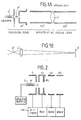
- the emission zone comprising the cathode C′, grid G′, first anode A1′ and second anode A2′ serves to form a beam of electrons which converge to a crossover point X′ between the grid G′ and first anode A1′ and thereafter diverge.
- the second and third anodes A2′, A3′ function as an electron lens L′ which images the crossover point X′ onto the screen S of the CRT.
- the size of the image on the screen S is dependent on the size of the crossover point and the magnification factor of the gun.
- the focal length of the lens L′ is adjusted by adjusting the voltage of the second anode A2′, which is conventionally referred to as the focussing anode.
- EP-A-0113113 describes an electron gun arrangement in which the potential at the second acceleration grid is greater than the potential at the first acceleration grid, and less than the potential at the final grid.
- US-A-4201933 describes an electron gun for a pick up tube.
- the voltage applied to the first accelerating electrode of the pick up tube exceeds that applied to the first focussing electrode.
- This electron gun includes a beam limiting hole provided at a beam disc electrode.
- One aspect of the present invention is concerned with reducing the size of the crossover, and thus of the image thereof on the screen, compared with the known gun.
- the voltage applied to the first anode in the series is higher than in a known gun as shown in Figure 1A and in particular is greater than the voltage applied to the focussing anode.
- a high electric field is formed between the grid and the first anode which tends to reduce the size of the crossover.
- an electron gun for emitting and focussing an electron beam comprising a cathode for emitting a beam of electrons; a grid for controlling the beam current; a series of anodes for directing and focussing the electron beam, the series including a first accelerating anode immediately after said grid, a main focussing anode immediately after said first accelerating anode and a final anode; and means for applying voltages to the anodes and for applying a modulating voltage between the grid and the cathode; the voltage (e.g. 5kV) applied to the first anode in the series being greater than the voltage (e.g.
- the voltage (e.g. 5kV) applied to the first anode in the series is at least fifty times greater than the range (e.g. 50V) of the modulating voltage between a beam cut-off voltage and a full emission voltage.
- the second aspect of the invention seeks to utilise this high voltage in controlling the beam size.
- an electron gun for emitting and focussing an electron beam, comprising a cathode for emitting a beam of electrons; a grid for controlling the beam current; a series of anodes for directing and focussing the beam current and including a first accelerating anode immediately after said grid, a main focussing anode immediately after said first accelerating anode, and a final anode; and means for applying voltages to the anodes and a beam limiting member and a modulating voltage between the grid and the cathode; wherein the beam limiting member is disposed to that side of the first anode which is remote from the grid, the beam limiting member having an aperture to limit the cross-section of the electron beam passing therethrough; and a voltage (e.g.
- 5kV is applied to the beam limiting member substantially equal to the voltage (e.g. 5kV) of the first anode in the series and more than the voltage of the main focussing anode, and a voltage is applied to the first anode in the series which is more than fifty times greater than the range of the modulating voltage between a beam cut-off voltage and a full emission voltage.
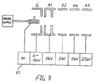
- the electron gun comprises a cathode C, a control grid G, a first anode A1, a second anode A2 and a third anode A3.
- a beam limiting aperture BL is provided.
- the aperture BL is provided in the first anode A1.
- the grid G and anodes A1, A2 and A3 are energised by a voltage supply arrangement VS; such a voltage supply arrangement is well known in the art.
- a conventional heater power supply energises the heater H of the cathode, which in this example is a conventional oxide cathode with a planar emission surface.
- the voltage supply arrangement VS energies the electrodes, as follows:
- the spacing S between the grid G and the first anode A1 is about 1.5mm.
- the result of the high field strength and the high voltage of the first anode is a small crossover between the grid G and first anode A1. At the crossover part the electrons are packed closely together and they tend to mutually repel each other increasing the size of the crossover. The high field strength combined with the high voltage of the first anode tends to cause the electrons to pack more closely together producing a small crossover.
- the position of the crossover varies as the modulating voltage VG applied to the grid G varies resulting in variation of focussing with modulating voltage.
- the modulating voltage VG is varied between cut off VGC (-50V in this example) to full emission VGF (OV).
- VGC cut off VGC
- OV full emission VGF
- the variation of focussing and the position of the crossover with modulation is reduced as compared to the known gun of Figure 1. It is believed that this improvement occurs because the ratio of the voltage V1 of the first anode to the range (VGF-VGC) of the modulating grid voltage is much greater than in the known guns. In the example, the ratio is 100:1. Preferably it is at least 80:1.
- the focus voltage applied to the focus electrode A2 is 500 V as compared to the 2.3 KV of the known gun. This is advantageous because it greatly simplifies the production of the focus voltage and allows "direct drive" of the focus electrode A2, and also simplifies dynamic variation of focus as the beam is scanned across the screen of a CRT, if dynamic focus variation is desired.
- the focus voltage (+500V) applied to the focus electrode A2 is less than the voltage (+5kV) applied to the first anode A1. If the beam limiter BL is provided on the first anode A1, electrons hitting it generate secondary electrons which, if they reached the screen of the CRT, would tend to reduce contrast and resolution. However, because the voltage of A2 is less than the voltage of A1, the secondary electrons are attracted back to A1 and so do not reach the screen improving contrast and resolution.
- the electron gun of Figure 2 is short, being shorter than the known gun of Figure 1.
- the main focus lens is dependent not only on the voltages applied to anodes A2 and A3 but also dependent on the voltage applied to A1. That dependence is apparent from the equipotential diagram of Figure 3.
- the electron gun of Figure 2 provides constant throughput independent of the EHT voltage applied to anode A3.
- Throughput is the ratio of beam current reaching the screen of the CRT to the current emitted by the cathode.
- Throughput is constant because, although changing the EHT voltage will change the focussing potential, since the beam limiting aperture connected to A1 is in a field free region, at e.g. a fixed voltage of 3 to 5kV, no change in the beam envelope at, or prior to, the aperture will occur.
- the high field strength in anode A1-grid G region gives a high cut-off value which is reduced by increasing the spacing of the grid G from the cathode C, thus easing problems of construction of the gun.
- EHT voltage applied to anode A3 has been described above as constant, it may be varied in the range approximately 7kV to 30kV.
- the gun may then be used in a penetron CRT in which the phosphors are selected according to the energy of the beam.
- the field strength between grid G and anode A1 is preferably greater than 2kV per mm and is preferably 3kV per mm or more, for a gun in which the grid aperture diameter is approximately 0.4mm.
- spot size at the screen can be increased or decreased by an increase or reduction of the grid aperture diameter, and that for an electron gun having a given beam exit angle at a given drive level, the spacing between grid and first anode is scaled in accordance with the change made in grid aperture diameter.
- An electron gun in accordance with the invention is applicable to a wide range of cathode ray tube screen sizes and resolution values, therefore it may use any grid aperture diameter in the range 0.2 to 1mm.
- the first anode voltage required must be at least 2kV, for the smaller grid aperture diameters (0.2 to 0.25 mm), but at least 3kV and preferably 5kV for the larger grid aperture diameters (0.5 to 1mm).
- the cathode C has been described hereinbefore as an oxide cathode having a planar emission face F. It may be replaced by a dispenser cathode having a planar emission face F; see Figure 4A.
- the cathode C may be replaced by a dispenser cathode having a more restricted planar emission face R as shown in Figure 4B.
- the emission surface is substantially smaller than the axially facing cross sectional area of the cathode.
- Such a cathode has the advantage of producing a beam of smaller conical angle than the cathode of Figure 4A (see Figures 5A, 5B) especially under conditions of maximum current output. The area from which the current is emitted increases with increasing emission.
- a gun in accordance with the invention is capable of being designed to give better corner resolution and depth of focus than a known bipotential gun as described with reference to Figures 1A and B. This is achievable by having a short gun having high through-put and a small angle of beam convergence at the screen of the CRT.
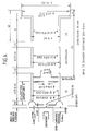
- Figure 6 shows an electron gun having good resolution in accordance with the invention, the Figure bearing illustrative dimensions. (Another gun (not illustrated) in accordance with the invention is shorter and has higher throughput but lesser resolution).
- Figure 7 is a cross section diagram of a CRT including the gun of Figure 6.
- the CRT is provided with a deflection coil DC and the assembly of the CRT and deflector coil is sealed within a housing H.
- the CRT is, as is conventional, provided with an EHT lead LD.
- an additional anode A4 is interposed between the main focus electrode A2 and final anode A3, connected to an intermediate voltage between V2 and V3, so that acceleration of the beam after passage through the focus electrode is accomplished in two stages (or, in a further extension, by a plurality of accelerating electrodes).
- the extra electrode A4 is connected electrically to the first anode A1.
- the resulting four-electrode focusing lens comprising A1, A2, A4, A3, has the ability to produce lower aberrations than a three-electrode lens A1, A2, A3, and the voltage applied to A2 (typically 1 to 4kV) remains lower than VA1, VA4 and VA3.
- a further short anode A5 is disposed between the first anode A1 and the main focus anode A2, and another short anode A6 is disposed between main focus anode A2 and the additional anode A4.
- the voltages applied to the electrodes may be as follows:
- the additional electrode A5 provides progressively controlled deceleration to the main focus anode A2 (which of the electrodes forming the electron lens is at the lowest voltage), and the additional anodes A6, A4 provide progressively controlled acceleration.
- This progressive control serves to reduce aberrations.
Landscapes
- Cold Cathode And The Manufacture (AREA)
- Manufacture Of Electron Tubes, Discharge Lamp Vessels, Lead-In Wires, And The Like (AREA)
- Electron Sources, Ion Sources (AREA)
- Particle Accelerators (AREA)
- Formation Of Various Coating Films On Cathode Ray Tubes And Lamps (AREA)
- X-Ray Techniques (AREA)
Claims (20)
- Un canon à électrons pour émettre et focaliser un faisceau d'électrons comprenant:- une cathode (C) pour émettre un faisceau d'électrons;- une grille (G) pour contrôler le courant du faisceau;- une série d'anodes pour diriger et pour focaliser le faisceau d'électrons, la série comprenant une première anode accélératrice (A1) qui suit immédiatement ladite grille (G), une anode de focalisation principale (A2) qui suit immédiatement ladite première anode accélératrice (A1) et une anode finale (A3); et- des moyens (VS) pour appliquer des tensions aux anodes (A1, A2, A3) et pour appliquer une tension de modulation entre la grille (G) et la cathode (C), la tension (par exemple 5kV) appliquée à la première anode (A1) de la série étant supérieure à la tension (par exemple 500V) appliquée à l'anode de focalisation principale (A2) et inférieure à la tension appliquée à l'anode finale (A3),caractérisé en ce que
la tension (par exemple 5 kV) appliquée à la première anode (A1) de la série est au moins 50 fois supérieure à la gamme ou excursion (50 V) de la tension de modulation entre une tension de blocage du faisceau et une tension d'émission maximale. - Un canon selon la revendication 1, dans lequel la tension appliquée à la première anode de la série est au moins 80 fois supérieure à la gamme des tensions de modulation.
- Un canon à électrons pour émettre et focaliser un faisceau d'électrons comprenant:- une cathode (C) pour émettre un faisceau d'électrons;- une grille (G) pour contrôler le courant du faisceau;- une série d'anodes pour diriger et pour focaliser le faisceau d'électrons, la série comprenant une première anode accélératrice (A1) qui suit immédiatement ladite grille (G), une anode de focalisation principale (A2) qui suit immédiatement ladite première anode accélératrice (A1) et une anode finale (A3); et- des moyens (VS) pour appliquer des tensions aux anodes (A1, A2, A3)et un organe de limitation
du faisceau (BL) et pour appliquer une tension de modulation entre la grille (G) et la cathode (C);
dans lequel l'organe de limitation de faisceau (BL) est disposé du côté de la première anode (A1), qui est éloigné de la grille (G), l'organe de limitation de faisceau présentant une ouverture pour limiter la section transversale du faisceau d'électrons le traversant; et
dans lequel une tension (par exemple de 5 kV) est appliquée à l'organe de limitation de faisceau (BL) sensiblement égale à la tension (par exemple de 5 kV) de la première anode (A1) de la série et supérieure à la tension de l'anode de focalisation principale, et une tension est appliquée à la première anode (A1) de la série, qui est plus de 50 fois supérieure à la gamme de la tension de modulation entre une tension de blocage du faisceau et une tension d'émission maximale. - Un canon selon la revendication 3, dans lequel la première anode (A1) de la série et l'organe de limitation de faisceau (BL) sont montés ensemble et sont reliés électriquement, de telle sorte que la tension de l'organe de limitation soit égale à la tension appliquée à la première anode de la série.
- Un canon selon l'une quelconque des revendications précédentes, dans lequel le champ électrique nominal entre la première anode de la série et la grille est, pour la tension de grille correspondant à l'émission maximale, d'au moins 2 kV/mm.
- Un canon selon l'une quelconque des revendications précédentes, dans lequel le champ électrique nominal entre la première anode de la série et la grille est, pour la tension de grille correspondant à l'émission maximale, d'au moins 3 kV/mm.
- Un canon selon l'une quelconque des revendications précédentes, dans lequel la première anode A1 de la série est prolongée axialement pour y former une zone sensiblement exempte de champ électrique.
- Un canon selon l'une quelconque des revendications précédentes, dans lequel la première anode (A1) de la série comprend une pluralité d'éléments séparés axialement, maintenus sensiblement au même potentiel (Figure 6).
- Un canon selon l'une quelconque des revendications précédentes, dans lequel au moins une anode supplémentaire (A4) est disposée entre l'anode de focalisation principale (A2) et l'anode finale (A˝), l'anode supplémentaire, ou chacune des anodes supplémentaires étant maintenue à une tension (par exemple 5 kV) entre les tensions (par exemple 2 kV; 25 kV) de l'anode qui précède et de l'anode qui suit (A2, A3).
- Un canon selon l'une quelconque des revendication précédentes, dans lequel au moins une autre anode (A5) est disposée entre la première anode (A1) de la série) et l'anode de focalisation principale (A2), cette autre anode, ou chacune de ces autres anodes, étant maintenue à une tension (par exemple 4 kV) comprise entre les tensions (par exemple 5 kV, 3 kV) de l'anode qui précède et de l'anode qui suit (A1, A2).
- Un canon selon l'une quelconque des revendications précédentes, dans lequel l'intervalle entre l'anode finale (A3) et la première anode (A1) de la série est suffisamment faible pour que la lentille principale de focalisation soit sensiblement dépendante des tension appliquées à la première anode, à l'anode de focalisation principale et à l'anode finale (A1, A2, A3).
- Un canon selon l'une quelconque des revendications précédentes, dans lequel la tension appliquée à la première anode (A1) de la série est supérieure à 2 kV.
- Un canon selon la revendication 12, dans lequel la tension appliquée à la première anode de la série est d'environ 5kV.
- Un canon selon l'une quelconque de revendications précédentes, dans lequel la cathode est une cathode de réserve.
- Un canon selon l'une quelconque des revendications 1 à 13, dans lequel la cathode (C) est une cathode à oxyde.
- Un canon selon la revendication 14 ou 15, dans lequel la cathode (C) présente une surface d'émission sensiblement plus petite que la surface en section transversale de la cathode.
- Un canon selon l'une quelconque des revendications précédentes, dans lequel la tension appliquée à l'anode finale (A3) est variable.
- Un canon selon la revendication 17, dans lequel la tension de l'anode finale est variable dans la gamme de 7kV à 30kV.
- Un tube à rayon cathodique présentant un canon à électron, selon l'une quelconque des revendications précédentes.
- Un tube à rayon cathodique du type dit pénétron muni d'un canon à électron tel que revendiqué dans les revendication 16 ou 17.
Applications Claiming Priority (2)
| Application Number | Priority Date | Filing Date | Title |
|---|---|---|---|
| GB878728481A GB8728481D0 (en) | 1987-12-04 | 1987-12-04 | Electron gun |
| GB8728481 | 1987-12-04 |
Publications (3)
| Publication Number | Publication Date |
|---|---|
| EP0319328A2 EP0319328A2 (fr) | 1989-06-07 |
| EP0319328A3 EP0319328A3 (en) | 1990-05-30 |
| EP0319328B1 true EP0319328B1 (fr) | 1995-09-13 |
Family
ID=10628047
Family Applications (1)
| Application Number | Title | Priority Date | Filing Date |
|---|---|---|---|
| EP88311466A Expired - Lifetime EP0319328B1 (fr) | 1987-12-04 | 1988-12-02 | Canons à électrons pour tubes à rayons cathodiques |
Country Status (6)
| Country | Link |
|---|---|
| US (1) | US5034654A (fr) |
| EP (1) | EP0319328B1 (fr) |
| JP (1) | JPH01200541A (fr) |
| AT (1) | ATE127957T1 (fr) |
| DE (1) | DE3854466T2 (fr) |
| GB (1) | GB8728481D0 (fr) |
Families Citing this family (7)
| Publication number | Priority date | Publication date | Assignee | Title |
|---|---|---|---|---|
| GB2269267B (en) * | 1991-03-05 | 1995-02-15 | Secr Defence | Focusing means for cathode ray tubes |
| GB9104649D0 (en) * | 1991-03-05 | 1991-04-17 | Secr Defence | Focusing means for cathode ray tubes |
| US5159240A (en) * | 1991-12-09 | 1992-10-27 | Chunghwa Picture Tubes, Ltd. | Low voltage limiting aperture electron gun |
| US5287038A (en) * | 1992-05-14 | 1994-02-15 | Litton Systems, Inc. | High resolution electron gun |
| KR970009209B1 (en) * | 1994-01-22 | 1997-06-07 | Lg Electronics Inc | In-line type electron gun for crt |
| JPH11345577A (ja) * | 1998-06-03 | 1999-12-14 | Hitachi Ltd | カラー陰極線管 |
| US8084929B2 (en) | 2009-04-29 | 2011-12-27 | Atti International Services Company, Inc. | Multiple device shaping uniform distribution of current density in electro-static focusing systems |
Family Cites Families (4)
| Publication number | Priority date | Publication date | Assignee | Title |
|---|---|---|---|---|
| JPS53146531A (en) * | 1977-05-27 | 1978-12-20 | Hitachi Ltd | Pickup tube |
| US4374341A (en) * | 1980-10-15 | 1983-02-15 | North American Philips Consumer Electronics Corp. | Beam focusing means in a unitized tri-potential CRT electron gun assembly |
| EP0113113B1 (fr) * | 1982-12-29 | 1987-09-16 | Matsushita Electronics Corporation | Tube à rayons cathodiques |
| JPS6251137A (ja) * | 1985-08-29 | 1987-03-05 | Sony Corp | 陰極線管 |
-
1987
- 1987-12-04 GB GB878728481A patent/GB8728481D0/en active Pending
-
1988
- 1988-12-02 JP JP63306757A patent/JPH01200541A/ja active Pending
- 1988-12-02 AT AT88311466T patent/ATE127957T1/de not_active IP Right Cessation
- 1988-12-02 EP EP88311466A patent/EP0319328B1/fr not_active Expired - Lifetime
- 1988-12-02 DE DE3854466T patent/DE3854466T2/de not_active Expired - Fee Related
-
1990
- 1990-06-21 US US07/541,486 patent/US5034654A/en not_active Expired - Fee Related
Also Published As
| Publication number | Publication date |
|---|---|
| ATE127957T1 (de) | 1995-09-15 |
| GB8728481D0 (en) | 1988-04-27 |
| US5034654A (en) | 1991-07-23 |
| JPH01200541A (ja) | 1989-08-11 |
| EP0319328A3 (en) | 1990-05-30 |
| DE3854466T2 (de) | 1996-05-02 |
| EP0319328A2 (fr) | 1989-06-07 |
| DE3854466D1 (de) | 1995-10-19 |
Similar Documents
| Publication | Publication Date | Title |
|---|---|---|
| US6331752B1 (en) | Color cathode ray tube having a low dynamic focus voltage | |
| US4287450A (en) | Electric circuit arrangements incorporating cathode ray tubes | |
| US5034654A (en) | Beam focusing means for a CRT electron gun assembly | |
| US6339300B2 (en) | Color cathode ray tube with a reduced dynamic focus voltage for an electrostatic quadrupole lens thereof | |
| CN1058103C (zh) | 改善聚焦的阴极射线管 | |
| EP0570541B1 (fr) | Canon electronique a ouverture limitatrice basse tension | |
| KR960016431B1 (ko) | 음극선관용 전자총 | |
| CN1093829A (zh) | 电子枪 | |
| US4496877A (en) | Unipotential electron gun for short cathode ray tubes | |
| US5489814A (en) | Focusing means for cathode ray tubes | |
| EP0589522B1 (fr) | Tube à rayons cathodiques | |
| KR920010660B1 (ko) | 칼라음극선관용 전자총 | |
| EP0247688A2 (fr) | Tube à rayons cathodiques | |
| US4994713A (en) | Asymmetric unipotential electron beam focusing lens | |
| EP0275191A2 (fr) | Tube image couleur muni d'un canon à trois lentilles | |
| US4705985A (en) | Cathode-ray tube and electron gun structure therefor | |
| KR0173720B1 (ko) | 컬러음극선관 | |
| KR100228161B1 (ko) | 칼라 수상관용 전자총 | |
| EP0725973B1 (fr) | Tube a rayons cathodiques equipe d'un canon electronique et systeme de lentille electrostatique | |
| US7122977B2 (en) | Cathode-ray tube apparatus | |
| KR910003949Y1 (ko) | 다단접속형 음극선관용 전자총 | |
| JPS6025140A (ja) | 陰極線管装置 | |
| EP0214816A2 (fr) | Tubes à rayons cathodiques | |
| TH41925A (th) | อุปกรณ์หลอดรังสีแคโธดสี | |
| TH21341B (th) | อุปกรณ์หลอดรังสีแคโธดสี |
Legal Events
| Date | Code | Title | Description |
|---|---|---|---|
| PUAI | Public reference made under article 153(3) epc to a published international application that has entered the european phase |
Free format text: ORIGINAL CODE: 0009012 |
|
| AK | Designated contracting states |
Kind code of ref document: A2 Designated state(s): AT CH DE FR GB IT LI NL SE |
|
| PUAL | Search report despatched |
Free format text: ORIGINAL CODE: 0009013 |
|
| AK | Designated contracting states |
Kind code of ref document: A3 Designated state(s): AT CH DE FR GB IT LI NL SE |
|
| 17P | Request for examination filed |
Effective date: 19901130 |
|
| RAP1 | Party data changed (applicant data changed or rights of an application transferred) |
Owner name: RANK BRIMAR LIMITED |
|
| 17Q | First examination report despatched |
Effective date: 19930709 |
|
| RAP1 | Party data changed (applicant data changed or rights of an application transferred) |
Owner name: RANK BRIMAR LIMITED (UK REG. NO. 1365015) |
|
| RAP1 | Party data changed (applicant data changed or rights of an application transferred) |
Owner name: RANK BRIMAR LIMITED |
|
| GRAA | (expected) grant |
Free format text: ORIGINAL CODE: 0009210 |
|
| AK | Designated contracting states |
Kind code of ref document: B1 Designated state(s): AT CH DE FR GB IT LI NL SE |
|
| PG25 | Lapsed in a contracting state [announced via postgrant information from national office to epo] |
Ref country code: IT Free format text: LAPSE BECAUSE OF FAILURE TO SUBMIT A TRANSLATION OF THE DESCRIPTION OR TO PAY THE FEE WITHIN THE PRE;WARNING: LAPSES OF ITALIAN PATENTS WITH EFFECTIVE DATE BEFORE 2007 MAY HAVE OCCURRED AT ANY TIME BEFORE 2007. THE CORRECT EFFECTIVE DATE MAY BE DIFFERENT FROM THE ONE RECORDED.SCRIBED TIME-LIMIT Effective date: 19950913 Ref country code: AT Effective date: 19950913 |
|
| REF | Corresponds to: |
Ref document number: 127957 Country of ref document: AT Date of ref document: 19950915 Kind code of ref document: T |
|
| REF | Corresponds to: |
Ref document number: 3854466 Country of ref document: DE Date of ref document: 19951019 |
|
| ET | Fr: translation filed | ||
| PG25 | Lapsed in a contracting state [announced via postgrant information from national office to epo] |
Ref country code: SE Effective date: 19951213 |
|
| PGFP | Annual fee paid to national office [announced via postgrant information from national office to epo] |
Ref country code: CH Payment date: 19951231 Year of fee payment: 8 |
|
| REG | Reference to a national code |
Ref country code: CH Ref legal event code: PL |
|
| PLBE | No opposition filed within time limit |
Free format text: ORIGINAL CODE: 0009261 |
|
| STAA | Information on the status of an ep patent application or granted ep patent |
Free format text: STATUS: NO OPPOSITION FILED WITHIN TIME LIMIT |
|
| 26N | No opposition filed | ||
| PG25 | Lapsed in a contracting state [announced via postgrant information from national office to epo] |
Ref country code: LI Free format text: LAPSE BECAUSE OF FAILURE TO SUBMIT A TRANSLATION OF THE DESCRIPTION OR TO PAY THE FEE WITHIN THE PRESCRIBED TIME-LIMIT Effective date: 19961231 Ref country code: CH Free format text: LAPSE BECAUSE OF FAILURE TO SUBMIT A TRANSLATION OF THE DESCRIPTION OR TO PAY THE FEE WITHIN THE PRESCRIBED TIME-LIMIT Effective date: 19961231 |
|
| REG | Reference to a national code |
Ref country code: GB Ref legal event code: 732E |
|
| REG | Reference to a national code |
Ref country code: GB Ref legal event code: 732E |
|
| NLS | Nl: assignments of ep-patents |
Owner name: BRIMAR LIMITED |
|
| NLT1 | Nl: modifications of names registered in virtue of documents presented to the patent office pursuant to art. 16 a, paragraph 1 |
Owner name: RANK NEMO (RB) LIMITED |
|
| REG | Reference to a national code |
Ref country code: FR Ref legal event code: TP |
|
| PGFP | Annual fee paid to national office [announced via postgrant information from national office to epo] |
Ref country code: FR Payment date: 19981106 Year of fee payment: 11 |
|
| PGFP | Annual fee paid to national office [announced via postgrant information from national office to epo] |
Ref country code: GB Payment date: 19981118 Year of fee payment: 11 |
|
| PGFP | Annual fee paid to national office [announced via postgrant information from national office to epo] |
Ref country code: NL Payment date: 19981229 Year of fee payment: 11 |
|
| PGFP | Annual fee paid to national office [announced via postgrant information from national office to epo] |
Ref country code: DE Payment date: 19990223 Year of fee payment: 11 |
|
| PG25 | Lapsed in a contracting state [announced via postgrant information from national office to epo] |
Ref country code: GB Free format text: LAPSE BECAUSE OF NON-PAYMENT OF DUE FEES Effective date: 19991202 |
|
| PG25 | Lapsed in a contracting state [announced via postgrant information from national office to epo] |
Ref country code: NL Free format text: LAPSE BECAUSE OF NON-PAYMENT OF DUE FEES Effective date: 20000701 |
|
| GBPC | Gb: european patent ceased through non-payment of renewal fee |
Effective date: 19991202 |
|
| PG25 | Lapsed in a contracting state [announced via postgrant information from national office to epo] |
Ref country code: FR Free format text: LAPSE BECAUSE OF NON-PAYMENT OF DUE FEES Effective date: 20000831 |
|
| NLV4 | Nl: lapsed or anulled due to non-payment of the annual fee |
Effective date: 20000701 |
|
| PG25 | Lapsed in a contracting state [announced via postgrant information from national office to epo] |
Ref country code: DE Free format text: LAPSE BECAUSE OF NON-PAYMENT OF DUE FEES Effective date: 20001003 |
|
| REG | Reference to a national code |
Ref country code: FR Ref legal event code: ST |