EP0319492A2 - Distributeur automatique de marchandises cylindriques, en particulier de rouleaux de pièces de monnaie - Google Patents
Distributeur automatique de marchandises cylindriques, en particulier de rouleaux de pièces de monnaie Download PDFInfo
- Publication number
- EP0319492A2 EP0319492A2 EP19880830519 EP88830519A EP0319492A2 EP 0319492 A2 EP0319492 A2 EP 0319492A2 EP 19880830519 EP19880830519 EP 19880830519 EP 88830519 A EP88830519 A EP 88830519A EP 0319492 A2 EP0319492 A2 EP 0319492A2
- Authority
- EP
- European Patent Office
- Prior art keywords
- shutter
- slot
- bin
- coin
- packets
- Prior art date
- Legal status (The legal status is an assumption and is not a legal conclusion. Google has not performed a legal analysis and makes no representation as to the accuracy of the status listed.)
- Granted
Links
- 230000007246 mechanism Effects 0.000 claims abstract description 13
- 238000005096 rolling process Methods 0.000 claims description 5
- 238000013459 approach Methods 0.000 claims description 2
- 239000000463 material Substances 0.000 claims description 2
- 230000015572 biosynthetic process Effects 0.000 description 4
- 230000000694 effects Effects 0.000 description 2
- 239000002184 metal Substances 0.000 description 2
- 239000011449 brick Substances 0.000 description 1
- 230000001747 exhibiting effect Effects 0.000 description 1
- 238000000034 method Methods 0.000 description 1
- 239000007787 solid Substances 0.000 description 1
- 239000004575 stone Substances 0.000 description 1
- 230000001960 triggered effect Effects 0.000 description 1
Images

Classifications
-
- G—PHYSICS
- G07—CHECKING-DEVICES
- G07D—HANDLING OF COINS OR VALUABLE PAPERS, e.g. TESTING, SORTING BY DENOMINATIONS, COUNTING, DISPENSING, CHANGING OR DEPOSITING
- G07D1/00—Coin dispensers
- G07D1/02—Coin dispensers giving change
- G07D1/04—Coin dispensers giving change dispensing change equal to a sum deposited
-
- G—PHYSICS
- G07—CHECKING-DEVICES
- G07F—COIN-FREED OR LIKE APPARATUS
- G07F11/00—Coin-freed apparatus for dispensing, or the like, discrete articles
- G07F11/02—Coin-freed apparatus for dispensing, or the like, discrete articles from non-movable magazines
- G07F11/44—Coin-freed apparatus for dispensing, or the like, discrete articles from non-movable magazines in which magazines the articles are stored in bulk
Definitions
- the invention relates to an automatic dispenser for commodities of cylindrical shape in general, and for cylindrical packets of coins in particular. Widespread use is made of automatic cash dispensers to change paper money for coins packaged in tubular cardboard wrappers; such machines are employed at banks, especially, so as to avoid the formation of long queues at the service counters and speed up money-changing operations generally.
- the typical cash dispenser consists essentially in a cabinet-like structure containing a plurality of chutes arranged one beside the next, each carrying a given type of coin, and a release mechanism for each chute; the chutes are all connected to a bank note acceptor.
- Each chute is fashioned from two upright U-section channels disposed facing one another and set apart at a prescribed distance in such a way as to create a vertical enclosure into which the packets of coin are dropped from above.
- the dimensions of the channel sections are such that the chute accommodates the packets in a single column. More exactly, the packets may be stacked in a zig-zag formation rather than in direct vertical alignment, though never two or more abreast in the horizontal; such an arrangement is essential in guaranteeing a smooth and uninterrupted feed as the chute gradually empties out.
- the object of the invention is to embody an automatic dispenser in which considerable quantities of wrapped coin can be accommodated, several packets deep, without 'bridging' as in a conventional dispensers; thus, the bin is certain to empty out completely without jamming, and one gains a notably increased interval of time between restocking operations.
- a dispenser as characterized in the appended claims, in which use is made of a bin with an angled bottom that slopes down toward an outlet of height not less than twice the diameter of the coin dispensed, and an upright release mechanism, associated with the fixed wall of the bin above the outlet, comprising a shutter and a baffle disposed parallel and in contact with one another.
- the shutter affords a slot adjustable for height, and is reciprocated along its own axis between a raised position at which the packets of coin are received singly into the slot from the outlet of the bin, and a lowered position at which each packet is ejected by a knockout device; the baffle remains permanently in contact with the shutter, and reciprocates together with it through at least part of the distance separating the two positions.
- One advantage of the dispenser according to the invention is that of its simplicity in design and its secure operation, obtained by virtue of the fact that the area of the bin where the packets of coin might tend to jam is of variable volume.
- a futher advantage of the dispenser disclosed is that it features a bin of standard embodiment with easily adjustable components, which can be adapted to accommodate cylindrical commodities of different diameter and length.
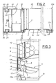
- coins pre-wrapped in cylindrical packets 3 of a given length L are changed, for bank notes or vouchers, by an automatic dispenser comprising an upright bin 1, and a release mechanism 4 which is located at the back of the bin as viewed from the position of the user or operator, denoted O .
- the dispenser cabinet will consist in a plurality of bins 1 and mechanisms 4, disposed side by side considered in the direction normal to the plane of fig 1, each containing a different denomination of coin.
- each bin 1 is encompassed by a rear wall 10 and a side wall 25, both fixed, and an adjustable side wall 2 disposed opposite to and parallel with the fixed side wall 25. More exactly, the fixed side wall 25 is disposed transversely to the axes of the cylindrical packets of coin 3, and bent through a right angle 25a to form the fourth and remaining wall of the bin 1.
- the adjustable side wall 2 is capable of movement through a direction parallel with the axes of the packets 3.
- One part of the side wall in question, denoted 2b, is attached to the remaining part 2c by means of a vertical hinge 2d, and provides a flap affording access to the inside of the bin 1 for restocking purposes (see fig 2);
- the bin 1 and the release mechanism 4 are mounted on rollers 60 that run on tracks 62 fastened to the structure of the outer cabinet, allowing the operator simply to run the bin 1 forward beyond the front of the cabinet to expose the flap 2b.
- the bin 1 is enclosed at bottom by a fixed shelf 9, affording a surface by which the stacked packets of coin 3 are supported and from which they ultimately roll off.
- 28 denotes a ramp located directly below the shelf 9, which accommodates the single packet of coins 3 dispensed from the bin 1 and is bent up at the front edge 28a to prevent it rolling beyond a given point, as will become clear in due course.
- the shelf 9 is angled, sloping downward toward the rear fixed wall 10 of the bin, whereas the ramp 28, which constitutes the dispensing tray 11 proper, slopes in precisely the opposite direction.
- 5 denotes an opening between the shelf 9 and the fixed rear wall 10, constituting the bin outlet, the overall height of which is not less than twice the diameter of the largest size of cylindrical packet 3 likely to be dispensed.
- the bin release mechanism 4 consists in a sliding shutter 6 and a baffle 7, both of which vertically disposed and fashioned preferably from materials with a low coefficient of friction.
- the baffle 7 is lightweight, fashioned from sheet metal looped into a C-profile of depth S substantially equal to a given horizontal distance through which the shelf 9 is made to project beyond the fixed rear wall 10, and lies breasted parallel with the rear wall 10 of the bin.
- the sliding shutter 6 is disposed parallel to and in permanent contact with the baffle 7, and made to reciprocate vertically, parallel with its own axis.
- the shutter is embodied essentially in two distinct and vertically aligned sections (fashioned likewise from sheet metal bent into suitable shape), namely, a first parallelepiped section 14 reflecting the fundamental geometry of the shutter and affording an inwardly-bent lip 14a at bottom on which each packet of coins 3 released from the bin 1 comes to rest, and a second section 13, consisting simply in a vertical panel fastened to the parallelepiped section 14, which is also bent inward to create a further lip 13a; the mutually opposed surfaces of the two lips 13a and 14a are disposed parallel and create a slot 8, angled in the same direction as that of the shelf 9, designed to accommodate one packet of coins 3 only.
- the second section 13 is fitted to the first 14 in such a way as to allow adjustment of its position through a vertical path, for example by means of bolts 31 and slots 32 (fig 1) in similar fashion to the adjustable wall 2 of the bin 1 (fig 2); in this way, it becomes possible to adjust the height of the slot 8 to match the diameter of the packet of coins 3 dispensed.
- the first section 14 is embodied with two vertical channels 30, one at each side, creating a pair of U-shaped tracks that are occupied by corresponding guide rollers 29 mounted to the sides of the bin 1.
- 24 denotes drive means with which the shutter 6 is associated, and by which it is reciprocated; in the example of fig 1, such means consist in a rod 33, driven by a crank arm 34 keyed to the shaft of a motor 35 mounted to the fixed side wall 25 of the bin.
- the first section 14, hence the entire shutter 6, is reciprocated by the drive means 24 at least between a raised receiving position, in which the slot 8 lies substantially in alignment with the shelf 9 and can thus accept a packet of coins 3 (see phantom line, fig 3), and a lowered knockout position in which the slot 8 coincides essentially with the topmost level of the tray 11 (fig 1).
- 12 denotes a knockout device associated with the shutter 6, which operates whenever the shutter is moved into the lowered position (fig 1).
- such a device 12 comprises a lever 16 hinged about a central pivot 16a to the first section 14 and exhibiting two arms, of which one arm 17 lies with at least its projecting end internally of the slot 8 and serves to prevent the packet of coins 3 rolling beyond the lip 14a; the remaining arm 19 carries an adjustable locator 19a (a simple setscrew) which is designed to register against a fixed stop as the shutter 6 approaches the knockout position. In the case in point, the fixed stop is afforded by the base 20 of the bin.
- the operating position of the device 12 is selected by means of an adjustable stop 18, associated with the first section 14, against which the lever 16 is urged under the weight of the released packet of coins 3.
- An automatic dispenser will also comprise a CPU (not illustrated), and two sensing elements 21 and 22 the purpose of which is to verify the presence or otherwise of a packet of coins 3, respectively in the slot 8, whenever the shutter 6 is in a stand-by position (shortly to be described), and on the shelf 9 of the bin.
- the stand-by position of the shutter 6 is that of fig 3 (bold line), with the slot 8 lying between the receiving and knockout positions, and in terms of operation, marginally prior to the moment in which the locator 19a engages the base 20 of the bin as the shutter descends.
- the bin itself Before setting the release mechanism 4 in readiness for initial commissioning, or when converting the bin to dispense a different denomination of coin, the bin itself must be adapted to accept the size of packet 3.
- the distance between the fixed wall 25 and the adjustable wall 2 must be set to match the length L of the packets of coin 3, using the screws 2a.
- the panel screws 31 and the stop 18 are adjusted to set the height and the depth of the slot 8, respectively; it will be seen from fig 1, in fact, that by raising the second section 13 in relation to the first section 14, the height of the slot 8 can be increased to accept coin of a diameter greater than that illustrated, and in this event, the depth must also be increased correspondingly by setting the stop 18 in such a way as to allow the lever arm 17 sufficient travel in the backwards direction to make certain that the packet 3 is encompassed completely by the slot 8, and thus prevented from projecting and striking against the edge of the shelf 9. Accordingly, the stop 18 is set in such a way that the forward-most crest of the packet 3 occupying the slot is aligned with the front surface 14b of the shutter 6. It will be seen in fig 3 that, with the shutter in the stand-by position, the arm 19 remains distanced from the base 20 of the bin 1 to ensure that the packet 3 remains stably inside the slot 8, whatever the diameter of coin.
- the motor 35 will start up and lower the shutter 6, bringing the locator 19a down onto the base 20 of the bin 1 and causing the lever 16 to rotate toward the tray 11 in the direction of the arrow f (fig 1).
- the packet of coins 3 is thus knocked forward by the relative arm 17 of the lever 16 and passes from the slot 8 onto the tray 11, rolling down in the direction of the user and coming to rest finally against the front edge 28a, from where it can be picked up.
- the shutter 6 begins returning upward to regain the receiving position.
- the packet of coins 3 next in line, hitherto held back by the shutter 6 itself is allowed to roll into the vacant slot 8, whereupon the rest of the packets shift down in the bin and settle behind it.
- the sensor 21 will fail to excite, a signal is triggered to denote the empty condition, and the bin is switched out of order.
- the shutter will continue to descend automatically to the lower position. The moment that the stock of packets 3 internally of the bin 1 falls below a given number, the area of the shelf 9 occupied by the remaining sensor 22 will be vacated, and the sensor 22 itself will excite, triggering a signal to advise that the bin is almost empty and needs restocking.
- the baffle 7 With each descent and ascent of the shutter 6, the baffle 7 is drawn with it as described above, with the result that one has a variation in the volume of the outlet zone 5 between the fixed rear wall 10 and the shelf 9; accordingly, the packets of coin 3 are prevented from forming bridges internally of the bin 1, and continue to be dispensed smoothly, without mishap, until the bin is emptied.
Landscapes
- Physics & Mathematics (AREA)
- General Physics & Mathematics (AREA)
- Control Of Vending Devices And Auxiliary Devices For Vending Devices (AREA)
- Vending Machines For Individual Products (AREA)
- Branching, Merging, And Special Transfer Between Conveyors (AREA)
- Basic Packing Technique (AREA)
- Testing Of Coins (AREA)
Priority Applications (1)
| Application Number | Priority Date | Filing Date | Title |
|---|---|---|---|
| AT88830519T ATE87110T1 (de) | 1987-12-04 | 1988-12-02 | Automatische ausgabevorrichtung fuer zylindrische waren, insbesondere fuer muenzrollen. |
Applications Claiming Priority (2)
| Application Number | Priority Date | Filing Date | Title |
|---|---|---|---|
| IT372287 | 1987-12-04 | ||
| IT03722/87A IT1221561B (it) | 1987-12-04 | 1987-12-04 | Distributore automatico di elementi cilindrici,in particolare di gruppi di monete |
Publications (3)
| Publication Number | Publication Date |
|---|---|
| EP0319492A2 true EP0319492A2 (fr) | 1989-06-07 |
| EP0319492A3 EP0319492A3 (en) | 1990-08-22 |
| EP0319492B1 EP0319492B1 (fr) | 1993-03-17 |
Family
ID=11111534
Family Applications (1)
| Application Number | Title | Priority Date | Filing Date |
|---|---|---|---|
| EP88830519A Expired - Lifetime EP0319492B1 (fr) | 1987-12-04 | 1988-12-02 | Distributeur automatique de marchandises cylindriques, en particulier de rouleaux de pièces de monnaie |
Country Status (7)
| Country | Link |
|---|---|
| US (1) | US4860922A (fr) |
| EP (1) | EP0319492B1 (fr) |
| AT (1) | ATE87110T1 (fr) |
| DE (1) | DE3879412T2 (fr) |
| ES (1) | ES2038788T3 (fr) |
| IT (1) | IT1221561B (fr) |
| ZA (1) | ZA889022B (fr) |
Cited By (4)
| Publication number | Priority date | Publication date | Assignee | Title |
|---|---|---|---|---|
| WO1995008817A1 (fr) * | 1993-09-22 | 1995-03-30 | Patrick Tiraboschi | Automate bancaire de distribution de rouleaux de pieces de monnaie |
| EP0813174A1 (fr) * | 1996-06-12 | 1997-12-17 | Groupe Meze (S.à.r.l.) | Procédé et dispositif de distribution automatique d'objets allongés, notamment de parapluies, et parapluie correspondant |
| US6763971B1 (en) * | 2002-09-18 | 2004-07-20 | Kui Kwong Tong | Candy dispenser |
| WO2014206226A1 (fr) * | 2013-06-27 | 2014-12-31 | 山东新北洋信息技术股份有限公司 | Module de distribution de rouleaux de pièces |
Families Citing this family (15)
| Publication number | Priority date | Publication date | Assignee | Title |
|---|---|---|---|---|
| US5988428A (en) * | 1996-10-28 | 1999-11-23 | Vendcraft Inc | Vending machine for cans with dispensing rod |
| JP3989597B2 (ja) * | 1997-03-25 | 2007-10-10 | 株式会社湯山製作所 | アンプル供給装置 |
| US5927539A (en) * | 1997-06-27 | 1999-07-27 | Dixie-Narco, Inc. | Modular vending machine with a dispensing detection device |
| US5938072A (en) * | 1997-09-16 | 1999-08-17 | Magner Corporation | Rolled coin dispenser |
| US6302294B1 (en) | 1999-11-08 | 2001-10-16 | Collier Safe Company, Inc. | Rolled coin dispenser |
| JP4236444B2 (ja) * | 2002-10-23 | 2009-03-11 | サンデン株式会社 | 自動販売機 |
| JP3684227B2 (ja) * | 2002-12-02 | 2005-08-17 | 照明 伊藤 | 分注チップ自動供給装置 |
| US7415815B2 (en) * | 2005-08-01 | 2008-08-26 | Conopco, Inc. | Tube dispensing magazine device and method |
| US7571833B2 (en) * | 2005-11-30 | 2009-08-11 | Fki Security Products | Bulk coin dispenser |
| US9149405B2 (en) * | 2009-03-03 | 2015-10-06 | Aesynt Incorporated | Medication storage and dispensing unit having a vial dispenser |
| BR112013030215A2 (pt) * | 2011-05-25 | 2016-12-06 | Antonio Domit | distribuidor de canudos de refrigerente |
| JP6398074B2 (ja) * | 2014-04-10 | 2018-10-03 | パナソニックIpマネジメント株式会社 | 部品供給装置 |
| US9907917B2 (en) * | 2015-06-24 | 2018-03-06 | Troy L. Knaub | Carpule warmer and dispenser |
| FR3043995B1 (fr) * | 2015-11-19 | 2017-12-22 | Imv Tech | Dispositif d'alimentation et de positionnement de paillettes de conditionnement de semence animale et installation de traitement comportant un tel dispositif |
| DE102016010793A1 (de) | 2016-09-09 | 2018-03-15 | Iwk Verpackungstechnik Gmbh | Tubenfüllmaschine mit einer Tubenkörper-Vereinzelungsvorrichtung |
Family Cites Families (8)
| Publication number | Priority date | Publication date | Assignee | Title |
|---|---|---|---|---|
| US1999887A (en) * | 1931-10-21 | 1935-04-30 | Walker Charles | Vending machine |
| US2840265A (en) * | 1954-01-11 | 1958-06-24 | Hiland B Noyes | Currency dispensing apparatus |
| US2873012A (en) * | 1958-04-01 | 1959-02-10 | Eugene J Lux | Vending machines |
| US3175669A (en) * | 1963-02-26 | 1965-03-30 | Superpack Vending Curacao N V | Device for vending cylindrical objects |
| US3743135A (en) * | 1970-12-21 | 1973-07-03 | C Brumley | Dispenser |
| JPS5569886A (en) * | 1978-11-17 | 1980-05-26 | Laurel Bank Machine Co | Article discharging unit |
| US4469245A (en) * | 1981-06-23 | 1984-09-04 | Casino Technology | Bulk loaded change dispensing apparatus |
| US4526292A (en) * | 1983-07-25 | 1985-07-02 | Jayvol Inc. | Chest for storing, heating and dispensing articles |
-
1987
- 1987-12-04 IT IT03722/87A patent/IT1221561B/it active
-
1988
- 1988-11-29 US US07/277,259 patent/US4860922A/en not_active Expired - Lifetime
- 1988-12-01 ZA ZA889022A patent/ZA889022B/xx unknown
- 1988-12-02 DE DE8888830519T patent/DE3879412T2/de not_active Expired - Fee Related
- 1988-12-02 ES ES198888830519T patent/ES2038788T3/es not_active Expired - Lifetime
- 1988-12-02 AT AT88830519T patent/ATE87110T1/de not_active IP Right Cessation
- 1988-12-02 EP EP88830519A patent/EP0319492B1/fr not_active Expired - Lifetime
Cited By (7)
| Publication number | Priority date | Publication date | Assignee | Title |
|---|---|---|---|---|
| WO1995008817A1 (fr) * | 1993-09-22 | 1995-03-30 | Patrick Tiraboschi | Automate bancaire de distribution de rouleaux de pieces de monnaie |
| FR2710436A1 (fr) * | 1993-09-22 | 1995-03-31 | Tiraboschi Patrick | Automate bancaire de distribution de rouleaux de pièces de monnaie. |
| US5722564A (en) * | 1993-09-22 | 1998-03-03 | Tiraboschi; Patrick | Automatic bank machine for distributing rolls of coins |
| EP0813174A1 (fr) * | 1996-06-12 | 1997-12-17 | Groupe Meze (S.à.r.l.) | Procédé et dispositif de distribution automatique d'objets allongés, notamment de parapluies, et parapluie correspondant |
| FR2749959A1 (fr) * | 1996-06-12 | 1997-12-19 | Groupe Meze | Procede et dispositif de distribution automatique d'objets allonges, notamment de parapluies, et parapluie correspondant |
| US6763971B1 (en) * | 2002-09-18 | 2004-07-20 | Kui Kwong Tong | Candy dispenser |
| WO2014206226A1 (fr) * | 2013-06-27 | 2014-12-31 | 山东新北洋信息技术股份有限公司 | Module de distribution de rouleaux de pièces |
Also Published As
| Publication number | Publication date |
|---|---|
| EP0319492A3 (en) | 1990-08-22 |
| DE3879412D1 (de) | 1993-04-22 |
| ATE87110T1 (de) | 1993-04-15 |
| ES2038788T3 (es) | 1993-08-01 |
| US4860922A (en) | 1989-08-29 |
| ZA889022B (en) | 1989-08-30 |
| IT1221561B (it) | 1990-07-12 |
| IT8703722A0 (it) | 1987-12-04 |
| EP0319492B1 (fr) | 1993-03-17 |
| DE3879412T2 (de) | 1993-08-19 |
Similar Documents
| Publication | Publication Date | Title |
|---|---|---|
| EP0319492B1 (fr) | Distributeur automatique de marchandises cylindriques, en particulier de rouleaux de pièces de monnaie | |
| US5167345A (en) | Dual dispenser | |
| AU725879B2 (en) | Process for operating a cash register terminal and cash register terminal | |
| US7429213B2 (en) | Automatic coin aligning apparatus and method | |
| US4759551A (en) | Coin projecting amusement device | |
| US5938072A (en) | Rolled coin dispenser | |
| GB2134091A (en) | Dispensing mechanism for vending articles | |
| US5137134A (en) | Vending machine for newspapers and magazines | |
| US5876275A (en) | Escalator with adjustable coin guides | |
| JPH0544347Y2 (fr) | ||
| WO2004023404A1 (fr) | Changeur de monnaies | |
| EP3563355B1 (fr) | Distributeur de pièces de monnaie | |
| US5360369A (en) | Change machine | |
| EP0880758A1 (fr) | Systeme pour trier des pieces | |
| JP2001312758A (ja) | 硬貨集積投出装置 | |
| US20040224624A1 (en) | Token dispensing apparatus | |
| GB2310306A (en) | Coin handling system | |
| EP0261838A2 (fr) | Distributeur de pièces de monnaie | |
| AU643527B2 (en) | Improved change machine | |
| EP0728344B1 (fr) | Distributeur de pieces | |
| JP2515865Y2 (ja) | 硬貨包装機の棒金リフト装置 | |
| US3452900A (en) | Method and apparatus for dispensing extra-length cigarette packages from machines designed for ordinary-length packages | |
| GB2296359A (en) | Coin handling apparatus | |
| JPH0417089A (ja) | コイン取出装置 | |
| JPH0355684A (ja) | 棒金払出装置 |
Legal Events
| Date | Code | Title | Description |
|---|---|---|---|
| PUAI | Public reference made under article 153(3) epc to a published international application that has entered the european phase |
Free format text: ORIGINAL CODE: 0009012 |
|
| AK | Designated contracting states |
Kind code of ref document: A2 Designated state(s): AT BE CH DE ES FR GB LI NL SE |
|
| PUAL | Search report despatched |
Free format text: ORIGINAL CODE: 0009013 |
|
| AK | Designated contracting states |
Kind code of ref document: A3 Designated state(s): AT BE CH DE ES FR GB LI NL SE |
|
| 17P | Request for examination filed |
Effective date: 19900827 |
|
| 17Q | First examination report despatched |
Effective date: 19920427 |
|
| RAP3 | Party data changed (applicant data changed or rights of an application transferred) |
Owner name: ROMAGNOLI, MARINO Owner name: BRAGA, UMBERTO Owner name: NADALINI, RAFFAELE Owner name: RIGHETTI, CLAUDIO Owner name: MALSERVISI, WILLIAM |
|
| GRAA | (expected) grant |
Free format text: ORIGINAL CODE: 0009210 |
|
| AK | Designated contracting states |
Kind code of ref document: B1 Designated state(s): AT BE CH DE ES FR GB LI NL SE |
|
| PG25 | Lapsed in a contracting state [announced via postgrant information from national office to epo] |
Ref country code: SE Effective date: 19930317 Ref country code: NL Effective date: 19930317 Ref country code: LI Effective date: 19930317 Ref country code: CH Effective date: 19930317 Ref country code: BE Effective date: 19930317 Ref country code: AT Effective date: 19930317 |
|
| REF | Corresponds to: |
Ref document number: 87110 Country of ref document: AT Date of ref document: 19930415 Kind code of ref document: T |
|
| REF | Corresponds to: |
Ref document number: 3879412 Country of ref document: DE Date of ref document: 19930422 |
|
| ET | Fr: translation filed | ||
| REG | Reference to a national code |
Ref country code: CH Ref legal event code: PL |
|
| REG | Reference to a national code |
Ref country code: ES Ref legal event code: FG2A Ref document number: 2038788 Country of ref document: ES Kind code of ref document: T3 |
|
| NLV1 | Nl: lapsed or annulled due to failure to fulfill the requirements of art. 29p and 29m of the patents act | ||
| PG25 | Lapsed in a contracting state [announced via postgrant information from national office to epo] |
Ref country code: GB Effective date: 19931202 |
|
| PLBE | No opposition filed within time limit |
Free format text: ORIGINAL CODE: 0009261 |
|
| STAA | Information on the status of an ep patent application or granted ep patent |
Free format text: STATUS: NO OPPOSITION FILED WITHIN TIME LIMIT |
|
| 26N | No opposition filed | ||
| GBPC | Gb: european patent ceased through non-payment of renewal fee |
Effective date: 19931202 |
|
| PGFP | Annual fee paid to national office [announced via postgrant information from national office to epo] |
Ref country code: DE Payment date: 20041125 Year of fee payment: 17 |
|
| PGFP | Annual fee paid to national office [announced via postgrant information from national office to epo] |
Ref country code: FR Payment date: 20041208 Year of fee payment: 17 |
|
| PGFP | Annual fee paid to national office [announced via postgrant information from national office to epo] |
Ref country code: ES Payment date: 20041229 Year of fee payment: 17 |
|
| PG25 | Lapsed in a contracting state [announced via postgrant information from national office to epo] |
Ref country code: ES Free format text: LAPSE BECAUSE OF NON-PAYMENT OF DUE FEES Effective date: 20051203 |
|
| PG25 | Lapsed in a contracting state [announced via postgrant information from national office to epo] |
Ref country code: DE Free format text: LAPSE BECAUSE OF NON-PAYMENT OF DUE FEES Effective date: 20060701 |
|
| PG25 | Lapsed in a contracting state [announced via postgrant information from national office to epo] |
Ref country code: FR Free format text: LAPSE BECAUSE OF NON-PAYMENT OF DUE FEES Effective date: 20060831 |
|
| REG | Reference to a national code |
Ref country code: FR Ref legal event code: ST Effective date: 20060831 |
|
| REG | Reference to a national code |
Ref country code: ES Ref legal event code: FD2A Effective date: 20051203 |