EP0319513A2 - Einrichtung zum Festlegen eines Fusses in einem Skischuh - Google Patents
Einrichtung zum Festlegen eines Fusses in einem Skischuh Download PDFInfo
- Publication number
- EP0319513A2 EP0319513A2 EP88890302A EP88890302A EP0319513A2 EP 0319513 A2 EP0319513 A2 EP 0319513A2 EP 88890302 A EP88890302 A EP 88890302A EP 88890302 A EP88890302 A EP 88890302A EP 0319513 A2 EP0319513 A2 EP 0319513A2
- Authority
- EP
- European Patent Office
- Prior art keywords
- tension member
- shell
- shaft
- shoe
- heel
- Prior art date
- Legal status (The legal status is an assumption and is not a legal conclusion. Google has not performed a legal analysis and makes no representation as to the accuracy of the status listed.)
- Granted
Links
- 210000002683 foot Anatomy 0.000 description 11
- 210000004744 fore-foot Anatomy 0.000 description 7
- 238000010276 construction Methods 0.000 description 3
- 230000035807 sensation Effects 0.000 description 2
- 230000002411 adverse Effects 0.000 description 1
- 230000000717 retained effect Effects 0.000 description 1
- 238000004904 shortening Methods 0.000 description 1
Images
Classifications
-
- A—HUMAN NECESSITIES
- A43—FOOTWEAR
- A43B—CHARACTERISTIC FEATURES OF FOOTWEAR; PARTS OF FOOTWEAR
- A43B5/00—Footwear for sporting purposes
- A43B5/04—Ski or like boots
- A43B5/0427—Ski or like boots characterised by type or construction details
- A43B5/0429—Adjustment of the boot to calf or shin, i.e. fibula, tibia
- A43B5/0433—Adjustment of the boot to calf or shin, i.e. fibula, tibia to the width of calf or shin, i.e. fibula, tibia
Definitions
- the invention relates to a device for fixing a foot in a ski boot with a pivoting shaft, a shell overlapping the instep and an extension overlapping the heel area in the interior of the shell or the shaft.
- Known ski shoe constructions are currently designed as a rear entry shoe with a foldable rear shaft part or as an overlap shoe with the possibility of a central entry into the shoe.
- Even with classic overlapping shoes a relatively free mobility of the shaft relative to the shell is permitted within predetermined limits, and in order to enable a comfortable entry into the shoe, a relatively large entry opening is usually also provided with overlapping shoes. Due to the great mobility of the shaft relative to the shell and due to the wide opening, which is required for a comfortable entry into the shoe, a number of measures have already been proposed, which ensure the fit of the foot in the shoe after closing the shoe should improve.
- shoes of this type are usually equipped with a shoehorn-like part in the heel area of the shoe, and cables have become known, by means of which the instep or forefoot area is pulled against the heel area of the shoe. Due to the anatomical shape of the foot, however, with relatively large openings for getting into the shoes, the secure hold of the foot in the heel area is not guaranteed if the inner contour of the shaft in the heel area runs essentially straight up to make it easier to get in .
- the invention now aims to provide a shoe of the type mentioned, in particular an overlap shoe at the beginning to create the type mentioned, in which a correspondingly large entry opening can be made available for the central entry and which, after closing, nevertheless enables an improvement in the hold of the foot in the heel area.
- the design according to the invention essentially consists in that a flexible tension member is arranged between the shaft or the shell and the extension overlapping the heel area, the free ends of which extend in the direction of the toe and are fixed to the shell at a distance from the heel are, wherein a free end of the tension member can be fixed in length and this end or the other free end of the tension member is fixed to a locking tab on the front of the shoe, in particular to a component having the point of application for a tensioning buckle.
- a tension member ensures a better overlap of the extension arranged in the heel area and better contact of this area with the heel, one of the anatomical shape of the Foot-appropriate fit of the foot created in the shoe, which shows a lower tendency to form unwanted pressure sensations on the foot.
- the design is advantageously made such that the component connected to the tension member on the closing flap is displaceably guided in an elongated hole.
- a further path for the tension member is available, which is available for entry, and the tensioning of the buckles automatically adjusts the previously selected setting of the tension member, since that in the elongated hole displaceably guided component can only be moved up to the respective limit of the elongated hole in the closing direction.
- variable length fixed end of the tension member has a bolt thread and interacts with a spindle drive fixed to the shell, in particular a nut mounted in a recess or opening in the shell .
- the tension member can be formed by a rope, since the corresponding pressure distribution is ensured by the tab arranged in the heel area or by the extension overlapping the heel area.
- a particularly uniform application of force over a large area can also be ensured when using ropes for the tension member if the design is such that the free ends of the tension member end or are at different distances from the sole on both sides of the longitudinal center of the shoe are fixed.
- the traction member wraps helically around the extension overlapping the heel area, so that a good pressure distribution is made possible without adverse pressure sensations.
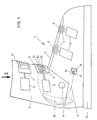
- FIG. 1 shows a schematic side view of a ski boot with the device according to the invention and
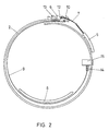
- FIG. 2 shows a view into the shaft of the ski boot according to FIG. 1.
- a ski boot 1 which has a rear part or a shaft 2 and a shell 3 which overlaps the forefoot area or the instep area.
- An inner boot usually arranged inside such a ski boot 1 is not shown for the sake of clarity.
- the shaft 2 can be pivoted to a limited extent relative to the shell 3 about a joint indicated schematically by 4.
- tensioning buckles 5 fixed to the shell 3 are indicated, which are provided with raster elements 6 which are generally sawtooth-shaped and also arranged on the shell Clamp 7 result in a fixation of the foot in the front area of the ski boot.
- an extension 8 is also indicated schematically in the interior of the shell 3 or the shaft 2, which extends over the heel.
- a flexible tension member 9 is arranged between the shaft 2 or the shell 3 and the extension 8 which extends over the heel region, as is indicated by the broken line in FIG.
- One end 10 of the tension member which can be formed in particular by a rope, is fixed to a locking tab 11 on the front of the shoe.
- the point of attack 12 is fixed in a simple manner to a component 6 which is essentially sawtooth-shaped for a further clamping buckle 5.
- the component 6 arranged with the tension member 9 at the articulation point 12 on the locking flap 11 and which cooperates with the bracket 7 of the tensioning buckle 5 is displaceably guided in an elongated hole, indicated schematically by 13, which results in advantages when putting on such a ski boot.
- the cable 9 can be arranged in the interior of the shaft 2 or the shell 3 in special guides in order to ensure the desired positioning of the tension member 9, such guides not being shown in FIG. 1 for the sake of clarity.
- the second free end 14 of the tension member 9 has a bolt thread and interacts with a spindle drive 15 fixed to the shell 3, this spindle drive being designed in a simple manner as a nut arranged in a recess 16 in the shell 3 .
- the free ends 10 and 14 are fixed on both sides of the longitudinal center of the shoe 1 at a different distance from the sole 17 of the shoe.
- the flexible tension member 9 extends on the inner surface of the shaft 2 or the shell 3 between the extension 8 which extends over the heel region and the shaft 2 or the shell 3.
- the one free end 10 is in turn connected to the component 6, which cooperates with the tensioning buckle 5, the articulation point 12 in turn being guided in an elongated hole 13 in the shaft 2.
- the second end 14 is in turn formed by a bolt thread, which interacts with the schematically indicated nut.
- the length of the tension member designed as a rope is changed by actuating the nut 15, with the shortening of the tension member 9 pressing the extension 8 over the heel area against the foot with the interposition of an inner shoe, not shown.
- a change in the definition of the bracket 7 on the component 6 causes essentially no change in length of the tension member 9, since the movement of the component 6 interacting with the bracket 7 of the tensioning buckle 5 primarily in a movement in the longitudinal direction of the shoe by reducing the opening diameter of the shaft and only is implemented in a second line in a movement of the component 6 in the circumferential direction of the shaft.
- a setting of the length of the cable 9 selected by actuation of the nut 15 for fixing the heel region of a foot in a ski boot is thus not changed by actuation of the tensioning buckle which interacts with the articulation point 12 of the second free end of the tension member 9.
- the heel flap or the extension 8 spanning the heel area can thus be tightened without changing the entire adjustment in the forefoot area.
Landscapes
- Health & Medical Sciences (AREA)
- General Health & Medical Sciences (AREA)
- Physical Education & Sports Medicine (AREA)
- Footwear And Its Accessory, Manufacturing Method And Apparatuses (AREA)
Abstract
Description
- Die Erfindung bezieht sich auf eine Einrichtung zum Festlegen eines Fußes in einem Skischuh mit einem schwenkbaren Schaft, einer den Rist übergreifenden Schale und einem den Fersenbereich übergreifenden Fortsatz im Inneren der Schale bzw. des Schaftes.
- Bekannte Skischuhkonstruktionen sind gegenwärtig als Heckeinstiegsschuh mit abklappbarem hinteren Schaftteil oder als Überlappschuh mit der Möglichkeit eines zentralen Einstieges in den Schuh ausgebildet. Auch bei klassischen Überlappschuhen wird eine relativ freie Beweglichkeit des Schaftes relativ zur Schale in vorbestimmten Grenzen zugelassen und um einen bequemen Einstieg in den Schuh zu ermöglichen, wird auch bei Überlappschuhen in der Regel eine relativ große Einstiegöffnung zur Verfügung gestellt. Auf Grund der großen Beweglichkeit des Schaftes relativ zur Schale und auf Grund der weiten Öffnung, wie sie für ein bequemes Einsteigen in den Schuh erforderlich ist, sind eine Reihe von Maßnahmen bereits vorgeschlagen worden, welche den Sitz des Fußes im Schuh nach dem Schließen des Schuhes verbessern sollen. Im besonderen sind derartige Schuhe zumeist mit einem schuhlöffelartig ausgebildeten Teil im Fersenbereich des Schuhes ausgestattet und es sind Seilzüge bekanntgeworden, über welche der Rist bzw. der Vorderfußbereich gegen den Fersenbereich des Schuhes gezogen wird. Auf Grund der anatomischen Form des Fußes ist jedoch bei relativ groß ausgestatteten Öffnungen für das Einsteigen in den Schuhen der sichere Halt des Fußes im Fersenbereich dann nicht gewährleistet, wenn die Innenkontur des Schaftes im Fersenbereich im wesentlichen geradlinig nach oben verläuft, um das Einsteigen zu erleichtern.
- Die Erfindung zielt nun darauf ab, einen Schuh der eingangs genannten Art, insbesondere einen Überlappschuh der eingangs genannten Art zu schaffen, bei welchem für den zentralen Einstieg eine entsprechend große Einstiegöffnung zur Verfügung gestellt werden kann und welcher nach dem Schließen dennoch eine Verbesserung des Haltes des Fußes im Fersenbereich ermöglicht. Zur Lösung dieser Aufgabe besteht die erfindungsgemäße Ausbildung im wesentlichen darin, daß zwischen dem Schaft bzw. der Schale und dem den Fersenbereich übergreifenden Fortsatz ein flexibles Zugglied angeordnet ist, dessen freie Enden in Richtung zur Schuhspitze verlaufen und in Abstand von der Ferse an der Schale festgelegt sind, wobei ein freies Ende des Zuggliedes längenveränderlich festlegbar ist und dieses Ende oder das andere freie Ende des Zuggliedes an einem Schließlappen an der Vorderseite des Schuhes, insbesondere an einem die Angriffstelle für eine Spannschnalle aufweisenden Bauteil festgelegt ist. Dadurch, daß nun abweichend von den bekannten Konstruktionen, mit welchen der Rist bzw. Vorderfußbereich in Richtung zur Ferse gezogen wird, ein Zugglied ein besseres Übergreifen des im Fersenbereich angeordneten Fortsatzes und besseres Anliegen dieses Bereiches an die Ferse gewährleistet, wird ein der anatomischen Form des Fußes gerechter Sitz des Fußes im Schuh geschaffen, welcher eine geringere Neigung zur Ausbildung von unerwünschten Druckempfindungen am Fuß zeigt. Durch die Verstellung der Länge des flexiblen Zuggliedes an einem freien Ende des flexiblen Zuggliedes kann die Einstellung für dieses Glied frei von den Zugbeanspruchungen, wie sie von Schnallen im Vorderfußbereich zum Schließen des Schuhes ausgeübt werden, gehalten werden. Es kann somit ein korrektes Schließen des Schuhes im Vorderfußbereich und eine unabhängige anatomisch korrekte Anpassung des Fersenbereiches durch Anziehen der Fersenlasche erzielt werden. Dadurch, daß eines der beiden freien Enden des Zuggliedes an einem Schließlappen an der Vorderseite des Schuhes, insbesondere an einem die Angriffstelle für eine Spannschnalle aufweisenden Bauteil festgelegt ist, wird eine besonders einfache Konstruktion geschaffen, wobei auch dann, wenn eines der beiden freien Enden des Zuggliedes an einem durch eine Spannschnalle fest spannbaren Lappen angelenkt ist, bei einem Spannen der Schnallen nur eine relativ geringe Verstellung der Anpassung im Fersenbereich erfolgt. Die gewählte Anpassung im Fersenbereich wird somit von einem mehr oder minder festen Schließen im Vorderfußbereich vollkommen unabhängig erhalten. Durch die Festlegung des zweiten Endes an einem Schließlappen, insbesondere an einer Spannschnalle, ist bei geöffnetem Schuh eine entsprechend große Durchtrittsöffnung sichergestellt und es erfolgt bei einem Schließen der Spannschnalle sowohl eine übliche Festlegung des Fußes im Schaft als auch die durch die gewählte Länge des Zuggliedes angepaßte und unabhängig einstellbare Festlegung der Fersenlasche.
- Um beim Einstieg eine besonders große Einstiegöffnung in den Schuh zu gewährleisten, ohne die vorgewählte Einstellung der Anpassung im Fersenbereich verändern zu müssen, ist mit Vorteil die Ausbildung so getroffen, daß der mit dem Zugglied am Schließlappen verbundene Bauteil in einem Langloch verschieblich geführt ist. Auf diese Weise wird nach dem Öffnen der Schnallen aufgrund des Langloches ein weiterer Weg für das Zugglied freigegeben, welcher für den Einstieg zur Verfügung steht, und durch das Spannen der Schnallen wird selbsttätig die zuvor gewählte Einstellung des Zuggliedes wiederum eingestellt, da sich der im Langloch verschieblich geführte Bauteil nur bis zu der jeweiligen Begrenzung des Langloches im Schließsinne verschieben läßt.
- Eine besonders einfache Verstell- und Einstellmöglichkeit für den Paßsitz im Fersenbereich läßt sich dadurch verwirklichen, daß das längenveränderlich festgelegte freie Ende des Zuggliedes ein Bolzengewinde aufweist und mit einem an der Schale festgelegten Spindeltrieb, insbesondere einer in einer Ausnehmung oder Durchbrechung der Schale gelagerten Mutter, zusammenwirkt. Mit einer derartigen relativ klein bauenden Einrichtung kann ein großer Verstellweg erzielt werden, ohne daß die Schale des Schuhes in nennenswerter Weise vergrößert werden müßte.
- In besonders einfacher Weise kann das Zugglied von einem Seil gebildet sein, da die entsprechende Druckverteilung durch den im Fersenbereich angeordneten Lappen bzw. den den Fersenbereich übergreifenden Fortsatz gewährleistet ist.
- Eine besonders gleichförmige Krafteinleitung über eine große Fläche kann auch bei Verwendung von Seilen für das Zugglied dann sichergestellt werden, wenn die Ausbildung so getroffen ist, daß die freien Enden des Zuggliedes zu beiden Seiten der Längsmitte des Schuhes in voneinander verschiedenem Abstand von der Sohle enden bzw. festgelegt sind. Das Zugglied umschlingt hiebei den den Fersenbereich übergreifenden Fortsatz schraubenlinienförmig, so daß eine gute Druckverteilung ohne nachteilige Druckempfindungen ermöglicht wird.
- Die Erfindung wird nachfolgend an Hand eines in der Zeichnung dargestellten Ausführungsbeispieles näher erläutert. Fig.1 zeigt eine schematische Seitenansicht eines Skischuhes mit der erfindungsgemäßen Einrichtung und Fig.2 zeigt eine Ansicht in den Schaft des Skischuhes gemäß Fig.1.
- In der Zeichnung ist ein Skischuh 1 dargestellt, welcher einen Heckteil bzw. einen Schaft 2 sowie eine Schale 3 aufweist, welche den Vorderfußbereich bzw. den Ristbereich übergreift. Ein üblicherweise im Inneren eines derartigen Skischuhes 1 angeordneter Innenschuh ist der Übersichtlichkeit halber nicht dargestellt. Der Schaft 2 ist um ein schematisch mit 4 angedeutetes Gelenk relativ zur Schale 3 in begrenztem Ausmaß verschwenkbar. Im Ristbereich sind an der Schale 3 festgelegte Spannschnallen 5 angedeutet, welche über mit an ebenfalls der Schale angeordneten im allgemeinen sägezahnförmig ausgebildeten Rasterelementen 6 über Spannbügel 7 eine Festlegung des Fußes im Vorderbereich des Skischuhes ergeben. Im Fersenbereich des Skischuhes 1 ist weiters im Inneren der Schale 3 bzw. des Schaftes 2 ein Fortsatz 8 schematisch angedeutet, welcher die Ferse übergreift. Zwischen dem Schaft 2 bzw. der Schale 3 und dem den Fersenbereich übergreifenden Fortsatz 8 ist ein flexibles Zugglied 9 angeordnet, wie es in Fig.1 strichliert angedeutet ist. Ein Ende 10 des Zuggliedes, welches insbesondere von einem Seil gebildet sein kann, ist dabei an einem Schließlappen 11 an der Vorderseite des Schuhes festgelegt. Die Angriffsstelle 12 ist dabei in einfacher Weise an einem für eine weitere Spannschnalle 5 im wesentlichen sägezahnförmigen Bauteil 6 festgelegt. Dabei ist der mit dem Zugglied 9 an der Anlenkstelle 12 am Schließlappen 11 angeordnete Bauteil 6, welcher mit dem Bügel 7 der Spannschnalle 5 zusammenwirkt, in einem schematisch mit 13 angedeuteten Langloch verschieblich geführt, wodurch sich Vorteile beim Anziehen eines derartigen Skischuhes ergeben. Das Seil 9 kann im Inneren des Schaftes 2 bzw. der Schale 3 in speziellen Führungen angeordnet sein, um die gewünschte Positionierung des Zuggliedes 9 sicherzustellen, wobei derartige Führungen der Deutlichkeit halber in Fig.1 nicht dargestellt sind. Das zweite freie Ende 14 des Zuggliedes 9 weist bei der Ausführungsform nach Fig.1 ein Bolzengewinde auf und wirkt mit einem an der Schale 3 festgelegten Spindeltrieb 15 zusammen, wobei dieser Spindeltrieb in einfacher Weise als in einer Ausnehmung 16 der Schale 3 angeordnete Mutter ausgebildet ist. Wie aus Fig.1 deutlich ersichtlich, sind dabei die freien Enden 10 und 14 zu beiden Seiten der Längsmitte des Schuhes 1 in voneinander verschiedenem Abstand von der Sohle 17 des Schuhes festgelegt.
- Bei der Darstellung in Fig.2 sind die Bezugszeichen der Fig.1 beibehalten worden. Wie aus Fig.2 deutlich ersichtlich, erstreckt sich das flexible Zugglied 9 an der Innenfläche des Schaftes 2 bzw. der Schale 3 zwischen dem den Fersenbereich übergreifenden Fortsatz 8 und dem Schaft 2 bzw. der Schale 3. Das eine freie Ende 10 ist wiederum mit dem Bauteil 6, welcher mit der Spannschnalle 5 zusammenwirkt verbunden, wobei die Anlenkstelle 12 wiederum in einem Langloch 13 des Schaftes 2 geführt ist. Das zweite Ende 14 wird wiederum von einem Bolzengewinde gebildet, welches mit der schematisch angedeuteten Mutter zusammenwirkt. Die Länge des als Seil ausgebildeten Zuggliedes wird durch Betätigung der Mutter 15 verändert, wobei bei einer Verkürzung des Zuggliedes 9 der den Fersenbereich übergreifende Fortsatz 8 an den Fuß unter Zwischenschaltung eines nicht näher dargestellten Innenschuhes angepreßt wird. Demgegenüber bewirkt eine Änderung der Festlegung des Bügels 7 am Bauteil 6 im wesentlichen keine Längenveränderung des Zuggliedes 9, da die Bewegung des mit dem Bügel 7 der Spannschnalle 5 zusammenwirkenden Bauteiles 6 in erster Linie in eine Bewegung in Schuhlängsrichtung durch Verkleinerung des Öffnungsdurchmessers des Schaftes und erst in zweiter Linie in eine Bewegung des Bauteiles 6 in Umfangsrichtung des Schaftes umgesetzt wird. Eine durch Betätigung der Mutter 15 gewählte Einstellung der Länge des Seilzuges 9 zur Festlegung des Fersenbereiches eines Fußes in einem Skischuh wird somit durch Betätigung der Spannschnalle, welche mit der Anlenkstelle 12 des zweiten freien Endes des Zuggliedes 9 zusammenwirkt, nicht verändert. Es kann die Fersenlasche bzw. der den Fersenbereich übergreifende Fortsatz 8 somit angezogen werden, ohne die gesamte Anpassung im Vorfußbereich zu ändern.
Claims (5)
Applications Claiming Priority (2)
| Application Number | Priority Date | Filing Date | Title |
|---|---|---|---|
| AT3194/87 | 1987-12-03 | ||
| AT0319487A AT395936B (de) | 1987-12-03 | 1987-12-03 | Einrichtung zum festlegen eines fusses in einem skischuh |
Publications (3)
| Publication Number | Publication Date |
|---|---|
| EP0319513A2 true EP0319513A2 (de) | 1989-06-07 |
| EP0319513A3 EP0319513A3 (en) | 1990-04-11 |
| EP0319513B1 EP0319513B1 (de) | 1994-07-27 |
Family
ID=3546807
Family Applications (1)
| Application Number | Title | Priority Date | Filing Date |
|---|---|---|---|
| EP88890302A Expired - Lifetime EP0319513B1 (de) | 1987-12-03 | 1988-12-01 | Einrichtung zum Festlegen eines Fusses in einem Skischuh |
Country Status (5)
| Country | Link |
|---|---|
| US (1) | US5005302A (de) |
| EP (1) | EP0319513B1 (de) |
| JP (1) | JPH0636762B2 (de) |
| AT (2) | AT395936B (de) |
| DE (1) | DE3850860D1 (de) |
Cited By (1)
| Publication number | Priority date | Publication date | Assignee | Title |
|---|---|---|---|---|
| EP0410080A3 (en) * | 1989-04-17 | 1992-01-15 | Nordica S.P.A | Foot securing device, particularly for ski boots |
Families Citing this family (3)
| Publication number | Priority date | Publication date | Assignee | Title |
|---|---|---|---|---|
| USD569586S1 (en) * | 2004-11-18 | 2008-05-27 | Calzaturificio S.C.A.R.P.A. S.P.A. | Sport footwear |
| USD569585S1 (en) * | 2004-11-18 | 2008-05-27 | Calzaturificio S.C.A.R.P.A. S.P.A. | Sport footwear |
| EP4316304A1 (de) * | 2022-08-05 | 2024-02-07 | Rossignol Lange S.R.L. | Betätigungsvorrichtung für einen sportschuh |
Family Cites Families (10)
| Publication number | Priority date | Publication date | Assignee | Title |
|---|---|---|---|---|
| FR2553267B2 (fr) * | 1982-12-02 | 1986-02-28 | Salomon & Fils F | Dispositif de serrage et de fermeture pour chaussure de ski a entree arriere |
| IT1160723B (it) * | 1983-02-24 | 1987-03-11 | Nordica Spa | Scarpone da sci particolarmente ad entrata posteriore con dispositivo di bloccaggio del collo del piede |
| IT8322827U1 (it) * | 1983-09-02 | 1985-03-02 | Nordica Spa | Dispositivo del bloccaggio del piede particolarmente per scarponi ad entrata anteriore |
| FR2567374B1 (fr) * | 1984-07-13 | 1986-12-12 | Salomon Sa | Chaussure de ski alpin. |
| IT1184177B (it) * | 1985-03-22 | 1987-10-22 | Nordica Spa | Scarpone da sci ad entrata posteriore con bloccaggio della zona della caviglia |
| IT1186356B (it) * | 1985-11-04 | 1987-11-26 | Nordica Spa | Scarpone da sci con dispositivo di chiusura e con dispositivo di bloccaggio del piede ad azionamento elettrico |
| IT1186500B (it) * | 1985-12-24 | 1987-11-26 | Nordica Spa | Scarpone da sci con dispositivo di bloccaggio del piede |
| US4785555A (en) * | 1986-09-04 | 1988-11-22 | Nordica S.P.A. | Foot securing device, particularly for ski boots |
| US4811503A (en) * | 1986-10-22 | 1989-03-14 | Daiwa Seiko, Inc. | Ski boot |
| CH673376A5 (de) * | 1987-09-09 | 1990-03-15 | Lange Int Sa |
-
1987
- 1987-12-03 AT AT0319487A patent/AT395936B/de not_active IP Right Cessation
-
1988
- 1988-12-01 AT AT88890302T patent/ATE108982T1/de active
- 1988-12-01 EP EP88890302A patent/EP0319513B1/de not_active Expired - Lifetime
- 1988-12-01 DE DE3850860T patent/DE3850860D1/de not_active Expired - Fee Related
- 1988-12-02 JP JP63305835A patent/JPH0636762B2/ja not_active Expired - Lifetime
- 1988-12-02 US US07/279,067 patent/US5005302A/en not_active Expired - Fee Related
Cited By (1)
| Publication number | Priority date | Publication date | Assignee | Title |
|---|---|---|---|---|
| EP0410080A3 (en) * | 1989-04-17 | 1992-01-15 | Nordica S.P.A | Foot securing device, particularly for ski boots |
Also Published As
| Publication number | Publication date |
|---|---|
| AT395936B (de) | 1993-04-26 |
| US5005302A (en) | 1991-04-09 |
| DE3850860D1 (de) | 1994-09-01 |
| EP0319513A3 (en) | 1990-04-11 |
| EP0319513B1 (de) | 1994-07-27 |
| JPH01212502A (ja) | 1989-08-25 |
| JPH0636762B2 (ja) | 1994-05-18 |
| ATA319487A (de) | 1992-09-15 |
| ATE108982T1 (de) | 1994-08-15 |
Similar Documents
| Publication | Publication Date | Title |
|---|---|---|
| EP0316540B1 (de) | Sportschuh, insbesondere Skischuh | |
| DE3342121C2 (de) | Skistiefel | |
| DE2709694C2 (de) | Skistiefel | |
| AT397193B (de) | Skischuh | |
| EP0321714A2 (de) | Skischuh | |
| DE3524792A1 (de) | Alpiner skistiefel | |
| EP0261179B1 (de) | Einrichtung zum festlegen eines fusses oder innenschuhes im vorfuss- bzw. ristbereich einer schale | |
| DE3342331A1 (de) | Integriertes verschlusssystem fuer skischuhe | |
| DE69200359T2 (de) | Schischuh mit Schale und Schaft. | |
| DE3736931C2 (de) | ||
| AT395515B (de) | Einrichtung zum festlegen eines fusses oder innenschuhes in einem ski- oder bergschuh | |
| DE3876554T2 (de) | Schischuh mit fersenhalterung. | |
| DE69303554T2 (de) | Vorrichtung zum Festklemmen des Oberteils eines Skistiefels | |
| EP0319513B1 (de) | Einrichtung zum Festlegen eines Fusses in einem Skischuh | |
| CH528876A (de) | Skischuh | |
| EP0545965B1 (de) | Schnalle für schuhe, insbesondere skischuhe | |
| DE3834057A1 (de) | Alpiner skischuh | |
| CH673935A5 (de) | ||
| EP0171685B1 (de) | Skischuh | |
| DE4006892A1 (de) | Ski-schuh | |
| EP0400119B1 (de) | Skischuh | |
| EP0594554A1 (de) | Skischuh | |
| EP0586801A1 (de) | Skischuh | |
| AT526739B1 (de) | Skischuh | |
| DE4102180A1 (de) | Skistiefel |
Legal Events
| Date | Code | Title | Description |
|---|---|---|---|
| PUAI | Public reference made under article 153(3) epc to a published international application that has entered the european phase |
Free format text: ORIGINAL CODE: 0009012 |
|
| AK | Designated contracting states |
Kind code of ref document: A2 Designated state(s): AT CH DE FR IT LI |
|
| ITCL | It: translation for ep claims filed |
Representative=s name: BARZANO' E ZANARDO MILANO S.P.A. |
|
| EL | Fr: translation of claims filed | ||
| PUAL | Search report despatched |
Free format text: ORIGINAL CODE: 0009013 |
|
| AK | Designated contracting states |
Kind code of ref document: A3 Designated state(s): AT CH DE FR IT LI |
|
| 17P | Request for examination filed |
Effective date: 19900502 |
|
| 17Q | First examination report despatched |
Effective date: 19910926 |
|
| GRAA | (expected) grant |
Free format text: ORIGINAL CODE: 0009210 |
|
| RAP1 | Party data changed (applicant data changed or rights of an application transferred) |
Owner name: KOFLACH SPORT GESELLSCHAFT M.B.H. & CO. KG |
|
| AK | Designated contracting states |
Kind code of ref document: B1 Designated state(s): AT CH DE FR IT LI |
|
| REF | Corresponds to: |
Ref document number: 108982 Country of ref document: AT Date of ref document: 19940815 Kind code of ref document: T |
|
| REF | Corresponds to: |
Ref document number: 3850860 Country of ref document: DE Date of ref document: 19940901 |
|
| ITF | It: translation for a ep patent filed | ||
| ET | Fr: translation filed | ||
| PLBE | No opposition filed within time limit |
Free format text: ORIGINAL CODE: 0009261 |
|
| STAA | Information on the status of an ep patent application or granted ep patent |
Free format text: STATUS: NO OPPOSITION FILED WITHIN TIME LIMIT |
|
| 26N | No opposition filed | ||
| PGFP | Annual fee paid to national office [announced via postgrant information from national office to epo] |
Ref country code: FR Payment date: 19961030 Year of fee payment: 9 |
|
| PGFP | Annual fee paid to national office [announced via postgrant information from national office to epo] |
Ref country code: CH Payment date: 19961114 Year of fee payment: 9 |
|
| PGFP | Annual fee paid to national office [announced via postgrant information from national office to epo] |
Ref country code: AT Payment date: 19961223 Year of fee payment: 9 |
|
| PGFP | Annual fee paid to national office [announced via postgrant information from national office to epo] |
Ref country code: DE Payment date: 19970227 Year of fee payment: 9 |
|
| REG | Reference to a national code |
Ref country code: CH Ref legal event code: PFA Free format text: KOFLACH SPORT GESELLSCHAFT MBH & CO. KG TRANSFER- KOFLACH SPORT GESELLSCHAFT M.B.H. * KOFLACH SPORT GESELLSCHAFT M.B.H. TRANSFER- KOFLACH SPORT GESELLSCHAFT M.B.H. |
|
| PG25 | Lapsed in a contracting state [announced via postgrant information from national office to epo] |
Ref country code: AT Free format text: LAPSE BECAUSE OF NON-PAYMENT OF DUE FEES Effective date: 19971201 |
|
| PG25 | Lapsed in a contracting state [announced via postgrant information from national office to epo] |
Ref country code: LI Free format text: LAPSE BECAUSE OF NON-PAYMENT OF DUE FEES Effective date: 19971231 Ref country code: FR Free format text: THE PATENT HAS BEEN ANNULLED BY A DECISION OF A NATIONAL AUTHORITY Effective date: 19971231 Ref country code: CH Free format text: LAPSE BECAUSE OF NON-PAYMENT OF DUE FEES Effective date: 19971231 |
|
| REG | Reference to a national code |
Ref country code: FR Ref legal event code: TP Ref country code: FR Ref legal event code: CA |
|
| REG | Reference to a national code |
Ref country code: CH Ref legal event code: PL |
|
| PG25 | Lapsed in a contracting state [announced via postgrant information from national office to epo] |
Ref country code: DE Free format text: LAPSE BECAUSE OF NON-PAYMENT OF DUE FEES Effective date: 19980901 |
|
| REG | Reference to a national code |
Ref country code: FR Ref legal event code: ST |
|
| REG | Reference to a national code |
Ref country code: FR Ref legal event code: RM |
|
| PG25 | Lapsed in a contracting state [announced via postgrant information from national office to epo] |
Ref country code: IT Free format text: LAPSE BECAUSE OF NON-PAYMENT OF DUE FEES Effective date: 20051201 |