EP0319634A2 - Vorrichtung zum Reinigen einer Heizfläche, insbesondere einer Kesselanlage - Google Patents
Vorrichtung zum Reinigen einer Heizfläche, insbesondere einer Kesselanlage Download PDFInfo
- Publication number
- EP0319634A2 EP0319634A2 EP88102057A EP88102057A EP0319634A2 EP 0319634 A2 EP0319634 A2 EP 0319634A2 EP 88102057 A EP88102057 A EP 88102057A EP 88102057 A EP88102057 A EP 88102057A EP 0319634 A2 EP0319634 A2 EP 0319634A2
- Authority
- EP
- European Patent Office
- Prior art keywords
- plunger
- heating surface
- cleaning
- electromagnet
- designed
- Prior art date
- Legal status (The legal status is an assumption and is not a legal conclusion. Google has not performed a legal analysis and makes no representation as to the accuracy of the status listed.)
- Granted
Links
Images

Classifications
-
- F—MECHANICAL ENGINEERING; LIGHTING; HEATING; WEAPONS; BLASTING
- F28—HEAT EXCHANGE IN GENERAL
- F28G—CLEANING OF INTERNAL OR EXTERNAL SURFACES OF HEAT-EXCHANGE OR HEAT-TRANSFER CONDUITS, e.g. WATER TUBES OR BOILERS
- F28G7/00—Cleaning by vibration or pressure waves
Definitions
- the invention relates to a device for cleaning a heating surface, in particular a boiler system, consisting of a drivable knocking device.
- the invention is therefore based on the object of specifying a structurally simpler and more reliable device of the type mentioned.
- the knocking device is designed as a plunger that can be driven by an electromagnet.
- this electromagnet is designed with a fixed coil and a core attached to the plunger.
- the plunger is expediently held in its initial position with the aid of a spring. Without there is also the possibility of holding the plunger in its starting position with another coil.
- this plunger is to work in a space under positive or negative pressure, then at least the plunger with the core will be arranged in a housing.
- the coil or coils can then be arranged inside or outside as required.
- the housing mentioned as a cooling chamber. This can e.g. B. done by charging the housing with an appropriate cooling medium, such as nitrogen, but it could also be considered to cool the housing with outer ribs by the outside air.
- the device shown in the figures is used to clean a heating surface of a boiler system.
- it In its basic structure, it consists of a drivable tapping device.
- the heating surface 1 is arranged in a room 2 which is under positive or negative pressure.
- the knocking device is designed as a plunger 4 which can be driven by an electromagnet 3.
- This tapping device is flanged to a shoulder 5 on the space housing 6, which has a passage for the tappet 4.
- This passage 7 is also with a centric Füh tion for the plunger 4 provided.
- the electromagnet 3 is designed with a fixed coil 8 and a plunger 4 attached core 9.
- the plunger 4 is set in motion so that it strikes against the heating surface 1 or causes it to vibrate.
- the plunger 3 is returned to its original position or held in this position by means of a spring 10.
- the function of this spring 10 can also be taken over by a second coil 11, which would then cause the plunger 4 to move in the opposite direction.
- This further coil 11 is indicated schematically in the drawing figures.
- a housing 12 which accommodates at least the tappet 4 with the core 9 is provided.
- the coils 8, 11 and the spring 10 are also arranged in this housing 12.
- the coils 8, 11 are arranged outside the housing 12.
- the embodiment of this housing 12 as a cooling chamber is not shown in detail.
Landscapes
- Engineering & Computer Science (AREA)
- Chemical & Material Sciences (AREA)
- Combustion & Propulsion (AREA)
- Mechanical Engineering (AREA)
- General Engineering & Computer Science (AREA)
- Cleaning In General (AREA)
- Incineration Of Waste (AREA)
- Cleaning By Liquid Or Steam (AREA)
- Electromagnets (AREA)
Abstract
Description
- Die Erfindung betrifft eine Vorrichtung zum Reinigen einer Heizfläche, insbesondere einer Kesselanlage, bestehend aus einer antreibbaren Klopfvorrichtung.
- Bekannte Vorrichtungen der genannten Art (vgl. z. B. DE-OS 31 39 439) schlagen oder rütteln mit Hilfe einer bestimmten Mechanik (Pneumatik, Hydraulik oder Rotationsbewegung) die Heizfläche, so daß ein mehr oder minder großer Reinigungseffekt erzielt wird. Nachteilig ist der verhältnismäßig hohe Aufwand und die Störanfälligkeit bei Einsatz an konventionellen Kesselanlagen und insbesondere bei Kesselanlagen, die in einem geschlossenen Behälter unter Über- oder Unterdruck arbeiten.
- Der Erfindung liegt daher die Aufgabe zugrunde, eine konstruktiv einfachere und betriebssicherere Vorrichtung der eingangs genannten Art anzugeben.
- Zur Lösung dieser Aufgabe ist die Klopfvorrichtung als von einem Elektromagneten antreibbarer Stößel ausgebildet.
- Für die weitere Ausgestaltung bestehen im Rahmen der Erfindung mehrere Möglichkeiten. So ist nach einer bevorzugten Ausführungsform dieser Elektromagnet mit ortsfester Spule und auf dem Stößel befestigtem Kern ausgeführt. Zweckmäßigerweise wird der Stößel mit Hilfe einer Feder in seiner Ausgangslage gehalten. Ohne weiteres besteht aber auch die Möglichkeit, den Stößel mit einer weiteren Spule in seiner Ausgangslage zu halten. Soll dieser Stößel in einem unter Über- oder Unterdruck stehenden Raum arbeiten, so wird man zumindest den Stößel mit dem Kern in einem Gehäuse anordnen. Die Spule bzw. die Spulen können dann je nach Bedarf innen oder außen angeordnet werden. Arbeitet der Stößel mit dem Kern zumindest teilweise unter höheren Gastemperaturen, so empfiehlt es sich, das genannte Gehäuse als Kühlkammer auszubilden. Dies kann z. B. dadurch geschehen, daß das Gehäuse mit einem entsprechenden Kühlmedium, wie Stickstoff, beschickt wird, es könnte aber auch daran gedacht werden, das Gehäuse mit äußeren Rippen durch die Außenluft zu kühlen.
- Im folgenden wird die Erfindung anhand einer Ausführungsbeispiele darstellenden Zeichnung näher erläutert. Es zeigen
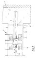
- Fig. 1 eine Vorrichtung zum Reinigen einer Heizfläche, und
- Fig. 2 eine abgewandelte Ausführungsform.
- Die in den Figuren gezeigte Vorrichtung dient zum Reinigen einer Heizfläche einer Kesselanlage. In ihrem grundsätzlichen Aufbau besteht sie aus einer antreibbaren Klopfvorrichtung.
- Im Ausführungsbeispiel ist die Heizfläche 1 in einem Raum 2 angeordnet, der unter Über- oder Unterdruck steht. Die Klopfvorrichtung ist als von einem Elektromagneten 3 antreibbarer Stößel 4 ausgebildet. Diese Klopfvorrichtung ist an einen Ansatz 5 am Raumgehäuse 6 angeflanscht, der einen Durchlaß für den Stößel 4 aufweist. Dieser Durchlaß 7 ist zugleich mit einer zentrischen Füh rung für den Stößel 4 versehen. Der Elektromagnet 3 ist mit ortsfester Spule 8 und dem Stößel 4 befestigtem Kern 9 ausgeführt. Durch Aktivieren des Elektromagneten 3 wird der Stößel 4 in Bewegung gesetzt, so daß er gegen die Heizfläche 1 schlägt bzw. diese in Schwingungen versetzt. Nach Abschalten des Stromes wird der Stößel 3 mittels einer Feder 10 in seine Ursprungslage zurückgebracht bzw. in dieser Lage gehalten. Die Funktion dieser Feder 10 kann auch von einer zweiten Spule 11 übernommen werden, die dann eine Bewegung des Stößels 4 in umgekehrter Richtung nach sich ziehen würde. Diese weitere Spule 11 ist in den Zeichnungsfiguren schematisch angedeutet.
- Bei beiden Ausführungsformen ist ein zumindest den Stößel 4 mit dem Kern 9 aufnehmendes Gehäuse 12 vorgesehen. Bei der Ausführungsform nach Fig. 1 sind auch die Spulen 8, 11 bzw. die Feder 10 in diesem Gehäuse 12 angeordnet. Bei der Ausführungsform nach Fig. 2 sind dagegen die Spulen 8, 11 außerhalb des Gehäuses 12 angeordnet. Im einzelnen nicht dargestellt ist die Ausführungsform dieses Gehäuses 12 als Kühlkammer.
Claims (5)
Priority Applications (1)
| Application Number | Priority Date | Filing Date | Title |
|---|---|---|---|
| AT88102057T ATE56535T1 (de) | 1987-12-07 | 1988-02-12 | Vorrichtung zum reinigen einer heizflaeche, insbesondere einer kesselanlage. |
Applications Claiming Priority (2)
| Application Number | Priority Date | Filing Date | Title |
|---|---|---|---|
| DE3741378 | 1987-12-07 | ||
| DE19873741378 DE3741378A1 (de) | 1987-12-07 | 1987-12-07 | Vorrichtung zum reinigen einer heizflaeche, insbesondere einer kesselanlage |
Publications (3)
| Publication Number | Publication Date |
|---|---|
| EP0319634A2 true EP0319634A2 (de) | 1989-06-14 |
| EP0319634A3 EP0319634A3 (en) | 1989-11-02 |
| EP0319634B1 EP0319634B1 (de) | 1990-09-12 |
Family
ID=6342018
Family Applications (1)
| Application Number | Title | Priority Date | Filing Date |
|---|---|---|---|
| EP88102057A Expired - Lifetime EP0319634B1 (de) | 1987-12-07 | 1988-02-12 | Vorrichtung zum Reinigen einer Heizfläche, insbesondere einer Kesselanlage |
Country Status (3)
| Country | Link |
|---|---|
| EP (1) | EP0319634B1 (de) |
| AT (1) | ATE56535T1 (de) |
| DE (1) | DE3741378A1 (de) |
Cited By (1)
| Publication number | Priority date | Publication date | Assignee | Title |
|---|---|---|---|---|
| WO1993002331A1 (en) * | 1991-07-23 | 1993-02-04 | A. Ahlstrom Corporation | A method of removing deposits from the walls of a gas cooler inlet duct, and a gas cooler inlet duct having a cooled elastic metal structure |
Families Citing this family (3)
| Publication number | Priority date | Publication date | Assignee | Title |
|---|---|---|---|---|
| DE4404068C1 (de) * | 1994-02-09 | 1995-08-17 | Wolfgang Engelhardt | Wärmetauscher |
| RU2151355C1 (ru) * | 1998-11-10 | 2000-06-20 | Кубанский государственный аграрный университет | Устройство для предотвращения образования накипи |
| RU2397420C1 (ru) * | 2009-05-05 | 2010-08-20 | Общество с ограниченной ответственностью "Пермский научно-исследовательский и проектный институт нефти" (ООО "ПермНИПИнефть") | Электромагнитный аппарат для борьбы с солеотложениями, преимущественно, в трубопроводах, в нефтедобывающих и водозаборных скважинах |
Family Cites Families (6)
| Publication number | Priority date | Publication date | Assignee | Title |
|---|---|---|---|---|
| US3183967A (en) * | 1961-12-29 | 1965-05-18 | Michael W Mettenleiter | Heat exchange unit |
| FR1557793A (de) * | 1967-12-15 | 1969-02-21 | ||
| DE7035269U (de) * | 1970-09-23 | 1971-07-22 | Herpen Co Kg La Mont Kessel | Waermetauscher mit reinigungsvorrichtung fuer die haengend angeordneten rohrbuendel. |
| FI52147C (fi) * | 1971-08-19 | 1977-06-10 | Ahlstroem Oy | Menetelmä ja laite höyrykattilan putkiston ulkopuolista puhdistusta va rten |
| FR2211868A5 (de) * | 1972-12-27 | 1974-07-19 | Electr Centre Atel | |
| DE2710153C2 (de) * | 1977-03-09 | 1985-06-20 | Alexander Bock | Vorrichtung zur intermittierenden Reinigung verschmutzter Flächen |
-
1987
- 1987-12-07 DE DE19873741378 patent/DE3741378A1/de not_active Ceased
-
1988
- 1988-02-12 AT AT88102057T patent/ATE56535T1/de not_active IP Right Cessation
- 1988-02-12 EP EP88102057A patent/EP0319634B1/de not_active Expired - Lifetime
Cited By (2)
| Publication number | Priority date | Publication date | Assignee | Title |
|---|---|---|---|---|
| WO1993002331A1 (en) * | 1991-07-23 | 1993-02-04 | A. Ahlstrom Corporation | A method of removing deposits from the walls of a gas cooler inlet duct, and a gas cooler inlet duct having a cooled elastic metal structure |
| US5443654A (en) * | 1991-07-23 | 1995-08-22 | A. Ahlstrom Corporation | Method of removing deposits from the walls of a gas cooler inlet duct, and a gas cooler inlet duct having a cooled elastic metal structure |
Also Published As
| Publication number | Publication date |
|---|---|
| EP0319634A3 (en) | 1989-11-02 |
| DE3741378A1 (de) | 1989-06-15 |
| EP0319634B1 (de) | 1990-09-12 |
| ATE56535T1 (de) | 1990-09-15 |
Similar Documents
| Publication | Publication Date | Title |
|---|---|---|
| EP0205807B1 (de) | Verfahren und Vorrichtung zum Betreiben eines elektromagnetischen Gaswechselventils | |
| DE2760264C2 (de) | Optische Abtastvorrichtung zum Abtasten von Aufzeichnungsspuren | |
| EP0319634B1 (de) | Vorrichtung zum Reinigen einer Heizfläche, insbesondere einer Kesselanlage | |
| DE3606874A1 (de) | Greifeinrichtung mit greiferbacken | |
| DE8205982U1 (de) | Vorrichtung zur umformung eines elektrischen signales in ein pneumatisches drucksignal | |
| EP0236850A3 (de) | Gasversorgungseinheit für pneumatisch betriebene Geräte | |
| EP0343325B1 (de) | Dampfdruckkochtopf/Kochstellen-System | |
| DE1502697A1 (de) | Elektromagnetisches Spannfutter | |
| EP0546450A1 (de) | Gurtaufroller für Sicherheitsgurte in Kraftfahrzeugen | |
| DE8717918U1 (de) | Vorrichtung zum Reinigen einer in einem Raumgehäuse befindlichen Heizfläche, insbesondere einer Kesselanlage | |
| DE740448C (de) | Resonanzfederantrieb | |
| DE2933981C2 (de) | Parkscheibe | |
| DE1080979B (de) | Verfahren zur selbstaendigen Regelung der Spannung von elektrischen Gasreinigungsanlagen | |
| DE2728383C2 (de) | Umpolgerät für Elektromagnet-Spannplatten | |
| DE402638C (de) | Einrichtung zum elektrischen Anschweissen von Metallstiften u. dgl. an Metallkoerper | |
| DE19703753A1 (de) | Werkzeuggreifer | |
| EP0644012A1 (de) | Elektrische Schweissenergiequelle mit integrierter Prozessüberwachung | |
| DE2806083C3 (de) | Automatischer Tütenhalter für eine durch einen E-Motor angetriebene Kaffee-, Getreide- oder Gewürzmühle | |
| DE873404C (de) | Stromstosssender zur Aussendung mehrerer Stromstossreihen | |
| DE4215999A1 (de) | Ziehmaschine des gleitenden Ziehprinzips zum Naßziehen von Stahl- und Nichteisenmetalldraht | |
| DE737101C (de) | Steuerung von elektrischen Triebfahrzeugen mit grosser Motorenleistung mittels Stufentransformator und Feinreglerkollektor | |
| DE69600517T2 (de) | Betriebseinheit für Schrittantriebe | |
| DE2558420A1 (de) | Geraetesteckvorrichtung fuer elektromagnetische geraete beim einsatz in der hydraulik und pneumatik | |
| AT123980B (de) | Vorrichtung zum Synchronisieren der Bewegung zweier von einem einzigen Motor angetriebener Wellen, die durch eine elastische Kupplung, z. B. eine Feder, miteinander verbunden sind. | |
| DE1903176B2 (de) | Vorrichtung zur Beeinflussung der Strömung des in einem Gehäuse aus einer Öffnung im freien Strahl austretenden Mediums |
Legal Events
| Date | Code | Title | Description |
|---|---|---|---|
| PUAI | Public reference made under article 153(3) epc to a published international application that has entered the european phase |
Free format text: ORIGINAL CODE: 0009012 |
|
| AK | Designated contracting states |
Kind code of ref document: A2 Designated state(s): AT BE ES IT NL SE |
|
| PUAL | Search report despatched |
Free format text: ORIGINAL CODE: 0009013 |
|
| AK | Designated contracting states |
Kind code of ref document: A3 Designated state(s): AT BE ES IT NL SE |
|
| 17P | Request for examination filed |
Effective date: 19891007 |
|
| 17Q | First examination report despatched |
Effective date: 19891218 |
|
| GRAA | (expected) grant |
Free format text: ORIGINAL CODE: 0009210 |
|
| AK | Designated contracting states |
Kind code of ref document: B1 Designated state(s): AT BE ES IT NL SE |
|
| PG25 | Lapsed in a contracting state [announced via postgrant information from national office to epo] |
Ref country code: ES Free format text: THE PATENT HAS BEEN ANNULLED BY A DECISION OF A NATIONAL AUTHORITY Effective date: 19900912 |
|
| REF | Corresponds to: |
Ref document number: 56535 Country of ref document: AT Date of ref document: 19900915 Kind code of ref document: T |
|
| ITF | It: translation for a ep patent filed | ||
| PGFP | Annual fee paid to national office [announced via postgrant information from national office to epo] |
Ref country code: BE Payment date: 19901212 Year of fee payment: 4 |
|
| PGFP | Annual fee paid to national office [announced via postgrant information from national office to epo] |
Ref country code: NL Payment date: 19910228 Year of fee payment: 4 |
|
| PLBE | No opposition filed within time limit |
Free format text: ORIGINAL CODE: 0009261 |
|
| STAA | Information on the status of an ep patent application or granted ep patent |
Free format text: STATUS: NO OPPOSITION FILED WITHIN TIME LIMIT |
|
| 26N | No opposition filed | ||
| PG25 | Lapsed in a contracting state [announced via postgrant information from national office to epo] |
Ref country code: BE Effective date: 19920228 |
|
| ITTA | It: last paid annual fee | ||
| BERE | Be: lapsed |
Owner name: OSCHATZ G.M.B.H. Effective date: 19920228 |
|
| PG25 | Lapsed in a contracting state [announced via postgrant information from national office to epo] |
Ref country code: NL Effective date: 19920901 |
|
| NLV4 | Nl: lapsed or anulled due to non-payment of the annual fee | ||
| EAL | Se: european patent in force in sweden |
Ref document number: 88102057.2 |
|
| PGFP | Annual fee paid to national office [announced via postgrant information from national office to epo] |
Ref country code: AT Payment date: 19960116 Year of fee payment: 9 |
|
| PGFP | Annual fee paid to national office [announced via postgrant information from national office to epo] |
Ref country code: SE Payment date: 19960125 Year of fee payment: 9 |
|
| PG25 | Lapsed in a contracting state [announced via postgrant information from national office to epo] |
Ref country code: AT Effective date: 19970212 |
|
| PG25 | Lapsed in a contracting state [announced via postgrant information from national office to epo] |
Ref country code: SE Effective date: 19970213 |
|
| EUG | Se: european patent has lapsed |
Ref document number: 88102057.2 |
|
| PG25 | Lapsed in a contracting state [announced via postgrant information from national office to epo] |
Ref country code: IT Free format text: LAPSE BECAUSE OF NON-PAYMENT OF DUE FEES;WARNING: LAPSES OF ITALIAN PATENTS WITH EFFECTIVE DATE BEFORE 2007 MAY HAVE OCCURRED AT ANY TIME BEFORE 2007. THE CORRECT EFFECTIVE DATE MAY BE DIFFERENT FROM THE ONE RECORDED. Effective date: 20050212 |