EP0319693A2 - Dispositif de rajustage pour freins de véhicule - Google Patents
Dispositif de rajustage pour freins de véhicule Download PDFInfo
- Publication number
- EP0319693A2 EP0319693A2 EP88117973A EP88117973A EP0319693A2 EP 0319693 A2 EP0319693 A2 EP 0319693A2 EP 88117973 A EP88117973 A EP 88117973A EP 88117973 A EP88117973 A EP 88117973A EP 0319693 A2 EP0319693 A2 EP 0319693A2
- Authority
- EP
- European Patent Office
- Prior art keywords
- worm shaft
- cap
- coupling
- adjusting device
- ring
- Prior art date
- Legal status (The legal status is an assumption and is not a legal conclusion. Google has not performed a legal analysis and makes no representation as to the accuracy of the status listed.)
- Granted
Links
- 230000008878 coupling Effects 0.000 claims abstract description 33
- 238000010168 coupling process Methods 0.000 claims abstract description 33
- 238000005859 coupling reaction Methods 0.000 claims abstract description 33
- 230000006835 compression Effects 0.000 claims abstract description 17
- 238000007906 compression Methods 0.000 claims abstract description 17
- 238000007789 sealing Methods 0.000 claims description 5
- 230000009471 action Effects 0.000 claims description 4
- 230000008859 change Effects 0.000 abstract description 5
- 238000006073 displacement reaction Methods 0.000 abstract description 2
- 230000007246 mechanism Effects 0.000 description 4
- 239000011248 coating agent Substances 0.000 description 3
- 238000000576 coating method Methods 0.000 description 3
- 239000011295 pitch Substances 0.000 description 3
- 230000008901 benefit Effects 0.000 description 2
- 239000012528 membrane Substances 0.000 description 2
- 241000237858 Gastropoda Species 0.000 description 1
- 230000007797 corrosion Effects 0.000 description 1
- 238000005260 corrosion Methods 0.000 description 1
Images




Classifications
-
- F—MECHANICAL ENGINEERING; LIGHTING; HEATING; WEAPONS; BLASTING
- F16—ENGINEERING ELEMENTS AND UNITS; GENERAL MEASURES FOR PRODUCING AND MAINTAINING EFFECTIVE FUNCTIONING OF MACHINES OR INSTALLATIONS; THERMAL INSULATION IN GENERAL
- F16D—COUPLINGS FOR TRANSMITTING ROTATION; CLUTCHES; BRAKES
- F16D65/00—Parts or details
- F16D65/38—Slack adjusters
- F16D65/40—Slack adjusters mechanical
- F16D65/52—Slack adjusters mechanical self-acting in one direction for adjusting excessive play
- F16D65/60—Slack adjusters mechanical self-acting in one direction for adjusting excessive play for angular adjustment of two concentric parts of the brake control systems
Definitions
- the invention relates to an automatic adjustment device for vehicle brakes with a housing serving as a brake lever, in which an adjusting gear consisting of worm and worm wheel is arranged, which works together via a coupling with spur gears and a drive member with a fixed lever protruding into the housing.
- a spur toothing of the clutch is arranged on the worm shaft and the other spur toothing of the clutch is arranged on a coupling ring which is displaceable on the worm shaft against a first compression spring.
- the worm shaft can be turned back manually at the end of the coupling against the direction of rotation of the adjustment.
- An adjustment device of the type described above is known for example from EP-OS 0 154 799.
- the adjustment can only be made after a coating change when the front end of the worm shaft has been exposed.
- a cap attached to the housing must be removed.
- a key can then be put on the worm shaft head, which simultaneously presses down the coupling ring and thereby releases the coupling consisting of the two spur gears.
- a disadvantage of this known adjustment device is that the worm shaft head and the coupling located in this area must be exposed for the adjustment. Moisture and dirt can get into the adjustment device and start the corrosion.
- Another disadvantage of the known adjusting device is that a brake disk is arranged on the worm shaft within the housing, which prevents the worm shaft from being inadvertently rotated. The The housing of the adjusting device is therefore wider by the thickness of the brake disc.
- the object of the invention is to create a simply constructed adjusting device which can be turned back by hand after a coating change against the direction of rotation of the adjustment and thus adjusted without the worm shaft head and the coupling devices having to be exposed. Another task is to simultaneously reduce the width of the housing to save weight.
- the contact surfaces of the extension and the flange lying outside the housing can be designed as a friction brake.
- a readjustment device designed according to this technical teaching has the advantage on the one hand that the adjustment can be carried out by hand by pressing the cap against the action of the second compression spring with a tool, without exposing the worm shaft head and the coupling arranged in this area, after a coating change.
- the proposed adjustment device also has the further advantage that the housing can be made smaller by the width of the friction brake provided in the prior art according to EP-OS 0 154 799 and therefore has a considerably lower weight because the friction brake is now outside the housing lies between the contact surfaces of the approach and the flange.
- the coupling between the worm shaft and the cap can consist of an external hexagon on the worm shaft and an internal hexagon on the cap.
- an internal hexagon on the pintle shaft as coupling device and an external hexagon on the cap.
- an elastic sealing lip can be formed on the ring, which bears against the cap under prestress. This prevents moisture and dirt from entering the gap between the cap and the ring.
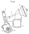
- a brake linkage consists of a membrane cylinder 2 fastened to the axle body 1 with a piston rod 3 which acts on a brake lever 4 which is arranged on a brake shaft (not shown). Due to the movement of the piston rod, the brake cams can be rotated in a drum brake and the brake shoes or their brake linings can be brought into contact with a brake drum.
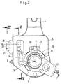
- a housing 5 is connected to an outer cover 6 and an inner cover 7, in which an adjusting device is arranged to compensate for the brake pad wear.
- the adjusting device consists of a worm 9 arranged on a worm shaft 8 and a worm wheel 10 fastened on the brake shaft (not shown) with an internal toothing.
- a coupling 11 is arranged on one side in the housing 5, which consists of a coupling ring 12 mounted on the worm shaft 8 with end teeth 13 and an end toothing 15 arranged on the underside of a hexagon head 14 designed as a hexagon.
- the two spur gears 13, 15 are held in engagement with a compression spring 16 arranged on the worm shaft 8.
- a lever 17 is arranged, which is guided with a sleeve 18 under the outer cover 6 into the housing 5 and at the other end has a ring 19 with a stop cam 20, which in a recess 21 of the housing 5 engages.
- the stop cam 20 and the recess 21 limit the maximum stroke of the brake lever 4 in relation to the lever 17, which is connected to a fixed part of the vehicle, for example the axle body 1.
- a flat drive member 22 is arranged between the sleeve 18 of the lever 17 and the coupling ring 12. This drive member 22 engages on the one hand with a round head 23 in the sleeve 18 and on the other hand with a hook 24 in a recess 25 of the coupling ring 12.
- the division of the teeth on the two spur gears 13, 15 and the dimensions of the recess 25 on the coupling ring 12 and the hook 24 on the drive member 22 must be coordinated with one another, so that only one adjustment by a maximum of one tooth length takes place in one stroke and the removal for the function of the brake necessary clearance is avoided.
- the hook 24 is chamfered on its outside and the recess 25 is larger than the hook 24, so that the front end of the hook 24 can emerge from the recess 25 during tangential displacement and the coupling ring 12 can no longer be adjusted thereafter.
- the coupling ring 12 is held in position with the end of the hook 24 so that the hook 24 can also reenter the recess 25 during the return stroke.
- the angle by which the coupling ring 12 can be adjusted to a maximum is slightly larger than the pitch of the teeth on the two spur gears 13, 15. In this way, an adjustment by several tooth pitches can be avoided on the return stroke.
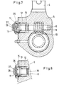
- the worm shaft 8 In order to adjust the readjustment device after changing the lining, the worm shaft 8 has to be turned back by hand against the direction of rotation of the readjustment direction. For this the clutch 11 between the two spur gears 13, 15 are opened. 7 to 11, an embodiment of a device for uncoupling and adjusting has been shown. This device consists of a ring 26 attached to the housing 5, a cap 27 and a second compression spring 28.
- An inwardly projecting projection 29 is formed on the ring 26 and engages over a flange 30 on the cap 27.
- the cap 27 is captively and positively, but rotatably and axially movably guided on the housing 5 or the ring 26.
- the outside of the cap 27 grinds on the end face of the flange 30.
- a friction brake 31 is formed between these two structural parts, which prevents the worm shaft from being inadvertently rotated counter to the direction of rotation of the adjustment during normal operation.
- the clutch opens first 11 with the spur gears 13, 15 and then an internal hexagon 32 engages over an external hexagon 33 on the worm shaft head 14. It is then possible to turn back the worm shaft 8 with a key attached to the cap 27, for example an external hexagon 34.
- the two compression springs 16, 28 push the cap 27 back into its starting position and then the coupling 11 again.
- the friction brake 31 between the flange 30 of the cap 27 and the shoulder 29 of the ring 26 is supplemented in that the second compression spring 28 is positively fixed to the cap 27 in a slot 35 and with its other end in a toothing 36 on the worm shaft 8 intervenes.
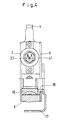
- FIGS. 12 to 14 Another embodiment of a device for uncoupling and adjusting has been shown in FIGS. 12 to 14, the mode of operation remaining the same, but an external hexagon 37 is arranged on the cap 27, which can snap into an internal hexagon on the worm shaft head 14. Analogously, a hexagon socket 39 is provided in the outside of the cap 27, which can be closed with a cover 40.
- a sealing lip 41 is integrally formed on the ring 26, which bears against the cap 27 under prestress, in order to prevent moisture and dirt from entering the gap between the ring 26 and the cap 27 penetrates.
- the cap 27 and the lid 40 can also be made of plastic. This keeps the weight of the slack adjuster low.
Landscapes
- Engineering & Computer Science (AREA)
- General Engineering & Computer Science (AREA)
- Mechanical Engineering (AREA)
- Braking Arrangements (AREA)
Applications Claiming Priority (2)
| Application Number | Priority Date | Filing Date | Title |
|---|---|---|---|
| DE3741519A DE3741519C1 (de) | 1987-12-08 | 1987-12-08 | Nachstellvorrichtung fuer Fahrzeugbremsen |
| DE3741519 | 1987-12-08 |
Publications (3)
| Publication Number | Publication Date |
|---|---|
| EP0319693A2 true EP0319693A2 (fr) | 1989-06-14 |
| EP0319693A3 EP0319693A3 (en) | 1990-03-28 |
| EP0319693B1 EP0319693B1 (fr) | 1991-11-13 |
Family
ID=6342100
Family Applications (1)
| Application Number | Title | Priority Date | Filing Date |
|---|---|---|---|
| EP88117973A Expired - Lifetime EP0319693B1 (fr) | 1987-12-08 | 1988-10-28 | Dispositif de rajustage pour freins de véhicule |
Country Status (2)
| Country | Link |
|---|---|
| EP (1) | EP0319693B1 (fr) |
| DE (3) | DE8717743U1 (fr) |
Cited By (3)
| Publication number | Priority date | Publication date | Assignee | Title |
|---|---|---|---|---|
| EP0569916A3 (fr) * | 1992-05-11 | 1995-02-01 | Cieci Srl | Mécanisme de compensation d'usure pour frein à sabots à expansion. |
| EP0762007A1 (fr) * | 1995-08-17 | 1997-03-12 | Grau Limited | Dispositif de rajustage pour frein de véhicule |
| WO2007024325A1 (fr) | 2005-08-23 | 2007-03-01 | Bendix Commercial Vehicle Systems Llc | Regleur de semelle de frein automatique |
Families Citing this family (2)
| Publication number | Priority date | Publication date | Assignee | Title |
|---|---|---|---|---|
| DE4218251C1 (de) * | 1992-06-03 | 1993-10-14 | Bergische Achsen Kotz Soehne | Nachstellvorrichtung für Fahrzeugbremsen |
| SE470526B (sv) * | 1992-11-18 | 1994-07-04 | Haldex Ab | Bromshävarm för en s-kambroms hos ett landsvägsfordon |
Family Cites Families (5)
| Publication number | Priority date | Publication date | Assignee | Title |
|---|---|---|---|---|
| US2631472A (en) * | 1949-11-16 | 1953-03-17 | John G Huntley | Slack adjusting mechanism |
| US3342293A (en) * | 1965-06-29 | 1967-09-19 | Bendix Westinghouse Automotive | Automatic slack adjuster |
| DE8407890U1 (de) * | 1984-03-15 | 1985-05-02 | Bergische Achsenfabrik Fr. Kotz & Söhne, 5276 Wiehl | Nachstellvorrichtung fuer fahrzeugbremsen |
| DE3409454A1 (de) * | 1984-03-15 | 1985-09-26 | Bergische Achsenfabrik Fr. Kotz & Söhne, 5276 Wiehl | Nachstellvorrichtung fuer fahrzeugbremsen |
| DE3625107C1 (en) * | 1986-07-24 | 1992-09-24 | Graubremse Gmbh | Automatic adjusting device for the expansion cams of a drum brake |
-
1987
- 1987-12-08 DE DE8717743U patent/DE8717743U1/de not_active Expired
- 1987-12-08 DE DE3741519A patent/DE3741519C1/de not_active Expired
-
1988
- 1988-10-28 EP EP88117973A patent/EP0319693B1/fr not_active Expired - Lifetime
- 1988-10-28 DE DE8888117973T patent/DE3866220D1/de not_active Expired - Fee Related
Cited By (4)
| Publication number | Priority date | Publication date | Assignee | Title |
|---|---|---|---|---|
| EP0569916A3 (fr) * | 1992-05-11 | 1995-02-01 | Cieci Srl | Mécanisme de compensation d'usure pour frein à sabots à expansion. |
| EP0762007A1 (fr) * | 1995-08-17 | 1997-03-12 | Grau Limited | Dispositif de rajustage pour frein de véhicule |
| WO2007024325A1 (fr) | 2005-08-23 | 2007-03-01 | Bendix Commercial Vehicle Systems Llc | Regleur de semelle de frein automatique |
| US7708122B2 (en) | 2005-08-23 | 2010-05-04 | Bendix Commercial Vehicle Systems Llc | Automatic slack adjuster |
Also Published As
| Publication number | Publication date |
|---|---|
| EP0319693A3 (en) | 1990-03-28 |
| EP0319693B1 (fr) | 1991-11-13 |
| DE8717743U1 (de) | 1989-11-16 |
| DE3866220D1 (de) | 1991-12-19 |
| DE3741519C1 (de) | 1989-05-03 |
Similar Documents
| Publication | Publication Date | Title |
|---|---|---|
| EP0739459B1 (fr) | Dispositif d'application d'un frein a disque, en particulier pour vehicules utilitaires lourds | |
| DE69617163T2 (de) | Reibungskupplung mit Nachstellvorrichtung, insbesondere für Kraftfahrzeuge | |
| DE9422342U1 (de) | Druckluftbetätigte Scheibenbremse | |
| DE3128799A1 (de) | Nachstellvorrichtung fuer eine trommelbremse | |
| EP0639246A1 (fr) | Dispositif de commande avec rattrapage de jeu automatique pour freins a disque, notamment pour poids lourds et autobus. | |
| DE8633923U1 (de) | Betätigungsvorrichtung mit selbsttätiger Nachstellung für Bremsen, insbesondere von Schwerlastfahrzeugen | |
| DE202011106746U1 (de) | Bremshebel für eine Trommelbremse | |
| EP0154799B1 (fr) | Dispositif de rajustage pour freins de véhicule | |
| DE69006238T2 (de) | Automatische Nachstellvorrichtung für Trommelbremse. | |
| DE2354322C2 (de) | Hydraulisch und mechanisch wirkende Bremsbetätigungsvorrichtung | |
| DE69722167T2 (de) | Reibungskupplung für kraftfahrzeuge mit einer verschleiss-nachstelleinrichtung | |
| DE2508577C2 (de) | Selbsttätige Nachstellvorrichtung für eine Scheibenbremse | |
| DE19514463C1 (de) | Bremszangeneinheit für Scheibenbremsen von Fahrzeugen, insbesondere Schienenfahrzeugen | |
| DE102014017156B3 (de) | Betätigungseinrichtung für eine Innenbackenbremse mit manuell betätigbarer Rückstelleinrichtung | |
| DE2659848A1 (de) | Automatische lueftspaltnachstellvorrichtung fuer eine mechanische scheibenbremse | |
| EP0319693B1 (fr) | Dispositif de rajustage pour freins de véhicule | |
| DE2904791A1 (de) | Selbstnachstellende scheibenkupplung | |
| EP0158034B1 (fr) | Dispositif de rattrapage de jeu pour freins de véhicule | |
| DE1630008A1 (de) | Selbsttaetige Nachstellvorrichtung,insbesondere fuer Fahrzeugbremsen | |
| DE2938735A1 (de) | Spreizbare scheibenbremse fuer fahrzeuge | |
| DE4218251C1 (de) | Nachstellvorrichtung für Fahrzeugbremsen | |
| DE3625107C1 (en) | Automatic adjusting device for the expansion cams of a drum brake | |
| DE2731725A1 (de) | Selbsttaetige gestaengenachstellvorrichtung fuer fahrzeugbremsgestaenge | |
| DE10148427A1 (de) | Verfahren zum Justieren eines Reibungskupplungssystems | |
| DE29522308U1 (de) | Scheibenbremse |
Legal Events
| Date | Code | Title | Description |
|---|---|---|---|
| PUAI | Public reference made under article 153(3) epc to a published international application that has entered the european phase |
Free format text: ORIGINAL CODE: 0009012 |
|
| AK | Designated contracting states |
Kind code of ref document: A2 Designated state(s): DE GB IT SE |
|
| PUAL | Search report despatched |
Free format text: ORIGINAL CODE: 0009013 |
|
| AK | Designated contracting states |
Kind code of ref document: A3 Designated state(s): DE GB IT SE |
|
| 17P | Request for examination filed |
Effective date: 19900322 |
|
| 17Q | First examination report despatched |
Effective date: 19901017 |
|
| GRAA | (expected) grant |
Free format text: ORIGINAL CODE: 0009210 |
|
| AK | Designated contracting states |
Kind code of ref document: B1 Designated state(s): DE GB IT SE |
|
| GBT | Gb: translation of ep patent filed (gb section 77(6)(a)/1977) | ||
| REF | Corresponds to: |
Ref document number: 3866220 Country of ref document: DE Date of ref document: 19911219 |
|
| ITF | It: translation for a ep patent filed | ||
| PLBE | No opposition filed within time limit |
Free format text: ORIGINAL CODE: 0009261 |
|
| STAA | Information on the status of an ep patent application or granted ep patent |
Free format text: STATUS: NO OPPOSITION FILED WITHIN TIME LIMIT |
|
| PGFP | Annual fee paid to national office [announced via postgrant information from national office to epo] |
Ref country code: GB Payment date: 19921016 Year of fee payment: 5 |
|
| PGFP | Annual fee paid to national office [announced via postgrant information from national office to epo] |
Ref country code: SE Payment date: 19921023 Year of fee payment: 5 |
|
| 26N | No opposition filed | ||
| PGFP | Annual fee paid to national office [announced via postgrant information from national office to epo] |
Ref country code: DE Payment date: 19921214 Year of fee payment: 5 |
|
| PG25 | Lapsed in a contracting state [announced via postgrant information from national office to epo] |
Ref country code: GB Effective date: 19931028 |
|
| PG25 | Lapsed in a contracting state [announced via postgrant information from national office to epo] |
Ref country code: SE Effective date: 19931029 |
|
| GBPC | Gb: european patent ceased through non-payment of renewal fee |
Effective date: 19931028 |
|
| PG25 | Lapsed in a contracting state [announced via postgrant information from national office to epo] |
Ref country code: DE Effective date: 19940701 |
|
| EUG | Se: european patent has lapsed |
Ref document number: 88117973.3 Effective date: 19940510 |
|
| PG25 | Lapsed in a contracting state [announced via postgrant information from national office to epo] |
Ref country code: IT Free format text: LAPSE BECAUSE OF NON-PAYMENT OF DUE FEES;WARNING: LAPSES OF ITALIAN PATENTS WITH EFFECTIVE DATE BEFORE 2007 MAY HAVE OCCURRED AT ANY TIME BEFORE 2007. THE CORRECT EFFECTIVE DATE MAY BE DIFFERENT FROM THE ONE RECORDED. Effective date: 20051028 |