EP0319723B1 - Méthode pour enlever des bouchons - Google Patents
Méthode pour enlever des bouchons Download PDFInfo
- Publication number
- EP0319723B1 EP0319723B1 EP88118607A EP88118607A EP0319723B1 EP 0319723 B1 EP0319723 B1 EP 0319723B1 EP 88118607 A EP88118607 A EP 88118607A EP 88118607 A EP88118607 A EP 88118607A EP 0319723 B1 EP0319723 B1 EP 0319723B1
- Authority
- EP
- European Patent Office
- Prior art keywords
- plug
- tube
- cavity
- cone
- force
- Prior art date
- Legal status (The legal status is an assumption and is not a legal conclusion. Google has not performed a legal analysis and makes no representation as to the accuracy of the status listed.)
- Expired - Lifetime
Links
Images

Classifications
-
- G—PHYSICS
- G21—NUCLEAR PHYSICS; NUCLEAR ENGINEERING
- G21C—NUCLEAR REACTORS
- G21C15/00—Cooling arrangements within the pressure vessel containing the core; Selection of specific coolants
-
- F—MECHANICAL ENGINEERING; LIGHTING; HEATING; WEAPONS; BLASTING
- F28—HEAT EXCHANGE IN GENERAL
- F28F—DETAILS OF HEAT-EXCHANGE AND HEAT-TRANSFER APPARATUS, OF GENERAL APPLICATION
- F28F11/00—Arrangements for sealing leaky tubes and conduits
- F28F11/02—Arrangements for sealing leaky tubes and conduits using obturating elements, e.g. washers, inserted and operated independently of each other
-
- B—PERFORMING OPERATIONS; TRANSPORTING
- B23—MACHINE TOOLS; METAL-WORKING NOT OTHERWISE PROVIDED FOR
- B23P—METAL-WORKING NOT OTHERWISE PROVIDED FOR; COMBINED OPERATIONS; UNIVERSAL MACHINE TOOLS
- B23P11/00—Connecting or disconnecting metal parts or objects by metal-working techniques not otherwise provided for
- B23P11/02—Connecting or disconnecting metal parts or objects by metal-working techniques not otherwise provided for by first expanding and then shrinking or vice versa, e.g. by using pressure fluids; by making force fits
-
- B—PERFORMING OPERATIONS; TRANSPORTING
- B23—MACHINE TOOLS; METAL-WORKING NOT OTHERWISE PROVIDED FOR
- B23P—METAL-WORKING NOT OTHERWISE PROVIDED FOR; COMBINED OPERATIONS; UNIVERSAL MACHINE TOOLS
- B23P19/00—Machines for simply fitting together or separating metal parts or objects, or metal and non-metal parts, whether or not involving some deformation; Tools or devices therefor so far as not provided for in other classes
- B23P19/02—Machines for simply fitting together or separating metal parts or objects, or metal and non-metal parts, whether or not involving some deformation; Tools or devices therefor so far as not provided for in other classes for connecting objects by press fit or for detaching same
- B23P19/025—For detaching only
-
- B—PERFORMING OPERATIONS; TRANSPORTING
- B25—HAND TOOLS; PORTABLE POWER-DRIVEN TOOLS; MANIPULATORS
- B25B—TOOLS OR BENCH DEVICES NOT OTHERWISE PROVIDED FOR, FOR FASTENING, CONNECTING, DISENGAGING, OR HOLDING
- B25B27/00—Hand tools, specially adapted for fitting together or separating parts or objects whether or not involving some deformation, not otherwise provided for
- B25B27/02—Hand tools, specially adapted for fitting together or separating parts or objects whether or not involving some deformation, not otherwise provided for for connecting objects by press fit or detaching same
- B25B27/023—Hand tools, specially adapted for fitting together or separating parts or objects whether or not involving some deformation, not otherwise provided for for connecting objects by press fit or detaching same using screws
-
- F—MECHANICAL ENGINEERING; LIGHTING; HEATING; WEAPONS; BLASTING
- F16—ENGINEERING ELEMENTS AND UNITS; GENERAL MEASURES FOR PRODUCING AND MAINTAINING EFFECTIVE FUNCTIONING OF MACHINES OR INSTALLATIONS; THERMAL INSULATION IN GENERAL
- F16L—PIPES; JOINTS OR FITTINGS FOR PIPES; SUPPORTS FOR PIPES, CABLES OR PROTECTIVE TUBING; MEANS FOR THERMAL INSULATION IN GENERAL
- F16L55/00—Devices or appurtenances for use in, or in connection with, pipes or pipe systems
- F16L55/10—Means for stopping flow in pipes or hoses
- F16L55/12—Means for stopping flow in pipes or hoses by introducing into the pipe a member expandable in situ
- F16L55/128—Means for stopping flow in pipes or hoses by introducing into the pipe a member expandable in situ introduced axially into the pipe or hose
- F16L55/13—Means for stopping flow in pipes or hoses by introducing into the pipe a member expandable in situ introduced axially into the pipe or hose the closure device being a plug fixed by plastic deformation
-
- Y—GENERAL TAGGING OF NEW TECHNOLOGICAL DEVELOPMENTS; GENERAL TAGGING OF CROSS-SECTIONAL TECHNOLOGIES SPANNING OVER SEVERAL SECTIONS OF THE IPC; TECHNICAL SUBJECTS COVERED BY FORMER USPC CROSS-REFERENCE ART COLLECTIONS [XRACs] AND DIGESTS
- Y02—TECHNOLOGIES OR APPLICATIONS FOR MITIGATION OR ADAPTATION AGAINST CLIMATE CHANGE
- Y02E—REDUCTION OF GREENHOUSE GAS [GHG] EMISSIONS, RELATED TO ENERGY GENERATION, TRANSMISSION OR DISTRIBUTION
- Y02E30/00—Energy generation of nuclear origin
- Y02E30/30—Nuclear fission reactors
-
- Y—GENERAL TAGGING OF NEW TECHNOLOGICAL DEVELOPMENTS; GENERAL TAGGING OF CROSS-SECTIONAL TECHNOLOGIES SPANNING OVER SEVERAL SECTIONS OF THE IPC; TECHNICAL SUBJECTS COVERED BY FORMER USPC CROSS-REFERENCE ART COLLECTIONS [XRACs] AND DIGESTS
- Y10—TECHNICAL SUBJECTS COVERED BY FORMER USPC
- Y10T—TECHNICAL SUBJECTS COVERED BY FORMER US CLASSIFICATION
- Y10T29/00—Metal working
- Y10T29/49—Method of mechanical manufacture
- Y10T29/4935—Heat exchanger or boiler making
- Y10T29/49352—Repairing, converting, servicing or salvaging
-
- Y—GENERAL TAGGING OF NEW TECHNOLOGICAL DEVELOPMENTS; GENERAL TAGGING OF CROSS-SECTIONAL TECHNOLOGIES SPANNING OVER SEVERAL SECTIONS OF THE IPC; TECHNICAL SUBJECTS COVERED BY FORMER USPC CROSS-REFERENCE ART COLLECTIONS [XRACs] AND DIGESTS
- Y10—TECHNICAL SUBJECTS COVERED BY FORMER USPC
- Y10T—TECHNICAL SUBJECTS COVERED BY FORMER US CLASSIFICATION
- Y10T29/00—Metal working
- Y10T29/49—Method of mechanical manufacture
- Y10T29/49718—Repairing
- Y10T29/49721—Repairing with disassembling
-
- Y—GENERAL TAGGING OF NEW TECHNOLOGICAL DEVELOPMENTS; GENERAL TAGGING OF CROSS-SECTIONAL TECHNOLOGIES SPANNING OVER SEVERAL SECTIONS OF THE IPC; TECHNICAL SUBJECTS COVERED BY FORMER USPC CROSS-REFERENCE ART COLLECTIONS [XRACs] AND DIGESTS
- Y10—TECHNICAL SUBJECTS COVERED BY FORMER USPC
- Y10T—TECHNICAL SUBJECTS COVERED BY FORMER US CLASSIFICATION
- Y10T29/00—Metal working
- Y10T29/49—Method of mechanical manufacture
- Y10T29/49815—Disassembling
- Y10T29/49821—Disassembling by altering or destroying work part or connector
-
- Y—GENERAL TAGGING OF NEW TECHNOLOGICAL DEVELOPMENTS; GENERAL TAGGING OF CROSS-SECTIONAL TECHNOLOGIES SPANNING OVER SEVERAL SECTIONS OF THE IPC; TECHNICAL SUBJECTS COVERED BY FORMER USPC CROSS-REFERENCE ART COLLECTIONS [XRACs] AND DIGESTS
- Y10—TECHNICAL SUBJECTS COVERED BY FORMER USPC
- Y10T—TECHNICAL SUBJECTS COVERED BY FORMER US CLASSIFICATION
- Y10T29/00—Metal working
- Y10T29/49—Method of mechanical manufacture
- Y10T29/49815—Disassembling
- Y10T29/49822—Disassembling by applying force
- Y10T29/49824—Disassembling by applying force to elastically deform work part or connector
-
- Y—GENERAL TAGGING OF NEW TECHNOLOGICAL DEVELOPMENTS; GENERAL TAGGING OF CROSS-SECTIONAL TECHNOLOGIES SPANNING OVER SEVERAL SECTIONS OF THE IPC; TECHNICAL SUBJECTS COVERED BY FORMER USPC CROSS-REFERENCE ART COLLECTIONS [XRACs] AND DIGESTS
- Y10—TECHNICAL SUBJECTS COVERED BY FORMER USPC
- Y10T—TECHNICAL SUBJECTS COVERED BY FORMER US CLASSIFICATION
- Y10T29/00—Metal working
- Y10T29/53—Means to assemble or disassemble
- Y10T29/53113—Heat exchanger
- Y10T29/53122—Heat exchanger including deforming means
Definitions
- tube and sheet heat exchangers for example those used in a nuclear steam generator, encounter problems in the form of tubes which become defective or damaged.
- these tubes were removed from operation by welding plugs into each end during a maintenance shutdown, and thereafter continuing the later operation of the steam generator with reduced capacity with the remaining tubes in operation.
- This form of maintenance is satisfactory until so many of the tubes are plugged as to make it economically unfeasible to continue operation at the reduced capacity.
- the tubes are presently plugged by plugs that can be removed at a later time. These plugs are mechanically expanded into the tubes without any welding being done.
- the unit When too many tubes have been removed from operation, the unit is shut down, the plugs are removed and the tubes are inspected and tested to see which of the defective tubes can be effectively repaired, for example by sleeving. If enough tubes can be repaired, the useful life of the steam generator can be greatly extended.
- the plugs may be loosened by means of a tool which spirals an electrical arc along the inside surface of the plug wall. As the arc melts a portion of its inner surface, the forces of solidification cause the wall of the plug to contract or shrink back, close to the original size that it was before it was expanded into the defective tube. A gripping mechanism is then used for pulling the plug from the tube end. Care must be taken during this action so as not to cause damage to the tubes.
- the internally threaded type of plug typically, is Inconel of a first hardness and includes an interior cavity having a threaded portion and a displaceable cone of a second and greater hardness for movement downwardly along an internal tapered surface of the plug cavity to create a component of force which radially expands the softer plug and holds it in place in sealing engagement with an inner surface of a defective tube.
- Inconel is nominally 13% (by weight) chromium, 79.5% nickel and 6.5% iron.
- the displaceable cone is typically made of hardened "17-4 P.H.” stainless steel. This material has a very low carbon content (0.07% max by weight) and is initially soft.
- the alloy's ferritic structure permits hardening to 40 to 45 Rockwell “C” by a simple aging treatment at 900°F to 1,150°F.
- the plug to be removed may be an Inconel "600 or 601" material having a typical yield strength of approximately 35,000 PSI. It is a softer than the "17-4 P.H.”, generally being below 32 Rockwell "C”. surface of the plug cavity to radially expand the softer plug to seal off the tube.
- the improved method of removal involves moving the displaceable cone out of its radially expanding position within the interior cavity of the plug, and according to the characterizing part of claim 1 applying a pushing force to the plug lengthwise within the cavity, to elongate the plug by installing an externally and internally threaded adapter in the threaded portion of the internal cavity and pulling the plug from the tube.
- the tube stretcher threadedly attaches to the internally threaded portion of the cavity and is torqued to advance the cone against the end of the plug to accomplish the elongation and radial reduction.
- An internally and externally threaded adapter preferably makes the attachment of the tube stretcher to the internally threaded portion.
- the adapter includes a surface for pulling engagement by a suitable mechanical puller.
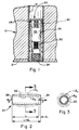
- the numeral 10 generally designates a portion of a tubesheet of a steam generator which includes a clad surface 12 and an Inconel tube 14 in contact with the tubesheet.
- an internally threaded plug generally designated by the numeral 20.
- the plug 20 is also of Inconel material and includes an interior cavity 22.
- the interior cavity 22 has an internal threaded portion 24 and a portion having a tapered surface 26.
- the tapered surface portion of the cavity contains a displaceable cone 30, of a material such as "17-4 P.H.” stainless steel having a hardness of 40 to 45 Rockwell "C”, which has been moved along the tapered surface to the position shown in full in Fig. 1 to create a component of force which radially expands the plug to a position schematically shown as A1 in Figs. 2 and 3. With the plug in this position, the steam generator tube 14 is withdrawn from service.
- the tube 14 is reopened by removal of the plug 20. This is accomplished by the displaceable cone 30 first being moved upwardly along tapered surface 26. A pneumatic hammer is convenient for this purpose. The cone 30 ends up in the position as shown by dotted lines in Fig. 1.
- the displaced cone 30 is at the top end 28 of the internal cavity portion 26 of the plug 20 and is in position for elongation of the plug 20 by means of a plug stretcher generally designated by the numeral 40.
- the plug stretcher 40 includes a hollow adapter member 42 having internal threads 44 and external threads 46 for engagement with threaded portion 24 of plug 20.
- the adapter 42 is conveniently provided of a material having a hardness of approximately 54 Rockwell "C".
- the internal threads 44 provide driving engagement for a threaded bolt-like member 50 and end pad 52 for applying a pushing force to the plug 20 lengthwise between the threaded portion 24 and the displaced cone 30 to stretch the plug and to reduce the plug diameter.
- a mechanical puller of any convenient type can be used to engage the flange surface 52 of the hollow adapter member 42 to pull the plug from the tube.
- the act of pulling the plug from the tube is easy because of the reduced diameter of the elongated plug 20 after it has been stretched by the tube stretcher 40 between threaded portion 24 and the top end 28 of the plug 20.
- the length of the plug changes from L to L+ ⁇ L upon the application of force P.
- the cross-sectional area of the plug material before elongation is A1 and after elongation is A2.
- the reduction in diameter is characterized by the equation, which states the change in length ⁇ L is equal to the force, 10,5000 pounds in this example, times the original distance between the points of force application, 24 and 28, on the plug divided by the original cross-sectional area A1, of the plug times the modulus of elasticity for the plug material.
- a reduction in diameter occurs as the force is applied when stretching the plug 20 to its yield point due mainly to the conservation of mass.
- a typical internally threaded mechanical tube plug only a few-thousandths of an inch reduction in diameter is required to substantially release the plug 20 for easy removal from the tube 14.
- a typical commercially available internally threaded plug 20′ is illustrated. As has been described, the tube stretcher 40 will easily elongate such a plug for removal from a steam generator tube. Like parts of the plug 20′ have been labelled with numbers corresponding to the parts of plug 20, primed.
Landscapes
- Engineering & Computer Science (AREA)
- Mechanical Engineering (AREA)
- General Engineering & Computer Science (AREA)
- Physics & Mathematics (AREA)
- Thermal Sciences (AREA)
- Plasma & Fusion (AREA)
- High Energy & Nuclear Physics (AREA)
- Heat Treatment Of Articles (AREA)
- Incineration Of Waste (AREA)
- Pipe Accessories (AREA)
Claims (3)
- Méthode de retrait d'un bouchon à filetage interne (20) d'un tube (14) de générateur de vapeur, ce bouchon ayant une dureté primaire et comprenant une cavité intérieure (22) ayant une portion filetée (24) et une portion contenant un cône mobile (30) d'une dureté secondaire et supérieure pour le déplacement le long d'une surface biseautée intérieure (26) de la cavité du bouchon pour créer une composante de force qui dilate radialement le bouchon plus tendre (20) d'une dureté secondaire moindre, et qui le maintient en place en engagement étanche avec une surface interne d'un tube défectueux (14), en déplaçant le cône mobile (30) hors de sa position d'expansion radiale dans la cavité intérieure (22), caractérisée par l'application au bouchon (20) d'une force de pression dans le sens de la longueur dans la cavité pour allonger le bouchon en installant un adaptateur (42) à filetage interne et externe dans la portion filetée (24) de la cavité intérieure (22) et l'extraction du bouchon du tube.
- Méthode selon la revendication 1 dans laquelle l'étape d'extraire le bouchon du tube comprend l'application d'une force à l'adaptateur.
- Méthode selon la revendication 1 dans laquelle l'étape d'application d'une force entre l'adaptateur (42) à filetage interne et externe et le cône mobile (30) comprend le couplage d'un organe allongé (50) dont les filets correspondent aux filets internes (44) de l'adaptateur , pour l'application d'une force de pression de l'organe allongé (50) contre le cône (30) et du cône (30) contre la surface intérieure de la cavité (22) du bouchon (20), allongeant ainsi le bouchon.
Applications Claiming Priority (2)
| Application Number | Priority Date | Filing Date | Title |
|---|---|---|---|
| US129572 | 1987-12-07 | ||
| US07/129,572 US4800637A (en) | 1987-12-07 | 1987-12-07 | Method of removing plugs |
Publications (3)
| Publication Number | Publication Date |
|---|---|
| EP0319723A2 EP0319723A2 (fr) | 1989-06-14 |
| EP0319723A3 EP0319723A3 (en) | 1990-06-13 |
| EP0319723B1 true EP0319723B1 (fr) | 1993-03-24 |
Family
ID=22440635
Family Applications (1)
| Application Number | Title | Priority Date | Filing Date |
|---|---|---|---|
| EP88118607A Expired - Lifetime EP0319723B1 (fr) | 1987-12-07 | 1988-11-09 | Méthode pour enlever des bouchons |
Country Status (4)
| Country | Link |
|---|---|
| US (1) | US4800637A (fr) |
| EP (1) | EP0319723B1 (fr) |
| KR (1) | KR930004873B1 (fr) |
| ES (1) | ES2040814T3 (fr) |
Cited By (1)
| Publication number | Priority date | Publication date | Assignee | Title |
|---|---|---|---|---|
| KR100794875B1 (ko) | 2000-06-19 | 2008-01-14 | 웨스팅하우스 일렉트릭 컴퍼니 엘엘씨 | 앵커 조립 장치와, 가이드 튜브의 구조적 완전무결성 개선장치 및 방법 |
Families Citing this family (19)
| Publication number | Priority date | Publication date | Assignee | Title |
|---|---|---|---|---|
| US5255717A (en) * | 1987-05-18 | 1993-10-26 | Westinghouse Electric Corp. | System for removing a plug from a heat exchanger tube |
| US4903392A (en) * | 1988-06-22 | 1990-02-27 | Westinghouse Electric Corp. | Method for removing a metallic plug from a tube by simultaneously heating and stretching the plug |
| DE3827036A1 (de) * | 1988-08-10 | 1990-02-15 | Man Energie Gmbh | Verfahren und vorrichtungen zum ausbauen von langen, aus zaehem werkstoff bestehenden innenkoerpern aus gebohrten elementen von schrumpfverbindungen |
| FR2645060B1 (fr) * | 1989-04-04 | 1991-07-19 | Framatome Sa | Procede et dispositifs d'extraction d'un bouchon d'obturation d'un tube de generateur de vapeur |
| FR2648944B1 (fr) * | 1989-06-23 | 1994-02-18 | Framatome | Dispositif d'obturation et de retenue d'un bouchon de fermeture etanche d'un tube de generateur de vapeur |
| FR2652673B2 (fr) * | 1989-06-23 | 1994-06-17 | Framatome Sa | Dispositif d'obturation et de retenue d'un bouchon de fermeture etanche d'un tube de generateur de vapeur. |
| US5194214A (en) * | 1991-05-13 | 1993-03-16 | Westinghouse Electric Corp. | Tube plug and method for plugging a tube |
| US5465483A (en) * | 1994-02-28 | 1995-11-14 | Westinghouse Electric Corporation | Method for removing a metallic plug from a tube |
| US5517740A (en) * | 1994-02-28 | 1996-05-21 | Westinghouse Electric Corporation | Pneumatic tool and method for plug removal |
| US6185817B1 (en) * | 1998-07-10 | 2001-02-13 | Duel Products, Inc. | Tool for removing a propeller from a drive shaft |
| US6189212B1 (en) | 1999-09-10 | 2001-02-20 | Westinghouse Electric Company Llc | Method for tube plug removal |
| EP2824337B1 (fr) * | 2012-03-07 | 2020-07-29 | Kabushiki Kaisha Kinki | Procédé pour extraire un élément de remplissage |
| WO2014159858A1 (fr) * | 2013-03-13 | 2014-10-02 | Saudi Arabian Oil Comapny | Bouchon fileté centralement pour tube d'échangeur de chaleur et outil de retrait |
| FR3014340B1 (fr) * | 2013-12-09 | 2016-01-15 | Areva Np | Dispositif perfectionne de percage de bouchons dans un generateur de vapeur |
| US9249916B2 (en) * | 2014-04-16 | 2016-02-02 | Jnt Technical Services, Inc. | Maximum expansion plug for heat exchanger tubes |
| SI3963258T1 (sl) | 2019-04-30 | 2024-10-30 | Framatome Gmbh | Prenosnik toplote s stabilizatorjem |
| IT202000001588A1 (it) * | 2020-01-28 | 2021-07-28 | Hudson Italiana Fbm | Tappo per sigillare tubi di scambiatori a fascio tubiero e mantello |
| JP7132283B2 (ja) * | 2020-06-30 | 2022-09-06 | 三菱重工業株式会社 | 蒸気発生器の分解方法 |
| US20240175647A1 (en) * | 2022-11-30 | 2024-05-30 | Saudi Arabian Oil Company | Ceramic tube plug |
Family Cites Families (9)
| Publication number | Priority date | Publication date | Assignee | Title |
|---|---|---|---|---|
| US2807079A (en) * | 1953-08-18 | 1957-09-24 | Greene Tweed & Co Inc | Device for installing seals |
| US3504420A (en) * | 1967-06-15 | 1970-04-07 | Ray F Shores | Plugging device |
| US4390042A (en) * | 1980-07-30 | 1983-06-28 | Westinghouse Electric Corp. | Tube plug |
| US4581801A (en) * | 1981-08-31 | 1986-04-15 | Westinghouse Electric Corp. | Sleeving method |
| US4754538A (en) * | 1983-11-15 | 1988-07-05 | Raychem Corporation | Annular tube-like driver |
| US4646816A (en) * | 1985-09-06 | 1987-03-03 | Samuel Rothstein | Simplified tube plugging |
| US4696102A (en) * | 1986-01-06 | 1987-09-29 | Combustion Engineering, Inc. | Collet type gripper |
| US4679315A (en) * | 1986-01-06 | 1987-07-14 | Combustion Engineering, Inc. | Hydraulic tube plug remover |
| US4734972A (en) * | 1986-01-15 | 1988-04-05 | Westinghouse Electric Corp. | Tube plug removal machine |
-
1987
- 1987-12-07 US US07/129,572 patent/US4800637A/en not_active Expired - Lifetime
-
1988
- 1988-11-09 EP EP88118607A patent/EP0319723B1/fr not_active Expired - Lifetime
- 1988-11-09 ES ES198888118607T patent/ES2040814T3/es not_active Expired - Lifetime
- 1988-12-05 KR KR1019880016162A patent/KR930004873B1/ko not_active Expired - Fee Related
Cited By (1)
| Publication number | Priority date | Publication date | Assignee | Title |
|---|---|---|---|---|
| KR100794875B1 (ko) | 2000-06-19 | 2008-01-14 | 웨스팅하우스 일렉트릭 컴퍼니 엘엘씨 | 앵커 조립 장치와, 가이드 튜브의 구조적 완전무결성 개선장치 및 방법 |
Also Published As
| Publication number | Publication date |
|---|---|
| KR930004873B1 (ko) | 1993-06-09 |
| US4800637A (en) | 1989-01-31 |
| EP0319723A3 (en) | 1990-06-13 |
| KR890010929A (ko) | 1989-08-11 |
| ES2040814T3 (es) | 1993-11-01 |
| EP0319723A2 (fr) | 1989-06-14 |
Similar Documents
| Publication | Publication Date | Title |
|---|---|---|
| US4800637A (en) | Method of removing plugs | |
| KR930006782B1 (ko) | 튜브 풀링 장치 | |
| JPH0428996B2 (fr) | ||
| EP0228684A2 (fr) | Mandrin à pince | |
| JPS62293095A (ja) | 管プラグ | |
| JP2510298B2 (ja) | 蒸気発生器の管の密封プラグ | |
| JPS58184497A (ja) | 管閉塞装置 | |
| JPS62293096A (ja) | 管プラグ | |
| US4829660A (en) | System for removing a plug from a heat exchanger tube | |
| US20060075617A1 (en) | Performance enhancing repair tool | |
| US5117548A (en) | Apparatus for loosening a mechanical plug in a heat exchanger tube | |
| US4903392A (en) | Method for removing a metallic plug from a tube by simultaneously heating and stretching the plug | |
| US5138754A (en) | Double gripper tube puller | |
| EP0516179A2 (fr) | Dispositif pour l'expansion et l'obturation d'une douille dans un tube entourant | |
| US3057631A (en) | Tube extractor | |
| US5168623A (en) | Tube puller tool assembly | |
| JP7189648B2 (ja) | グラウンドアンカー | |
| GB1582408A (en) | Method for the removal of tensile stresses | |
| US4831702A (en) | Method for fixing boiler tubes during replacement of same | |
| US6189212B1 (en) | Method for tube plug removal | |
| JPH0252570B2 (fr) | ||
| US5255717A (en) | System for removing a plug from a heat exchanger tube | |
| CA2591904A1 (fr) | Chauffage par induction et technique de depose par extraction des troncons de plaque tubulaire | |
| US6370758B1 (en) | Sleeved/interference fit (threaded) fastener installation tool | |
| US4780945A (en) | Method and an implement arrangement for the removal of fasteners in the form of rings |
Legal Events
| Date | Code | Title | Description |
|---|---|---|---|
| PUAI | Public reference made under article 153(3) epc to a published international application that has entered the european phase |
Free format text: ORIGINAL CODE: 0009012 |
|
| AK | Designated contracting states |
Kind code of ref document: A2 Designated state(s): BE ES FR SE |
|
| PUAL | Search report despatched |
Free format text: ORIGINAL CODE: 0009013 |
|
| AK | Designated contracting states |
Kind code of ref document: A3 Designated state(s): BE ES FR SE |
|
| 17P | Request for examination filed |
Effective date: 19901106 |
|
| 17Q | First examination report despatched |
Effective date: 19911118 |
|
| GRAA | (expected) grant |
Free format text: ORIGINAL CODE: 0009210 |
|
| AK | Designated contracting states |
Kind code of ref document: B1 Designated state(s): BE ES FR SE |
|
| ET | Fr: translation filed | ||
| PGFP | Annual fee paid to national office [announced via postgrant information from national office to epo] |
Ref country code: FR Payment date: 19930926 Year of fee payment: 6 |
|
| PGFP | Annual fee paid to national office [announced via postgrant information from national office to epo] |
Ref country code: SE Payment date: 19931001 Year of fee payment: 6 |
|
| PGFP | Annual fee paid to national office [announced via postgrant information from national office to epo] |
Ref country code: BE Payment date: 19931022 Year of fee payment: 6 |
|
| REG | Reference to a national code |
Ref country code: ES Ref legal event code: FG2A Ref document number: 2040814 Country of ref document: ES Kind code of ref document: T3 |
|
| PGFP | Annual fee paid to national office [announced via postgrant information from national office to epo] |
Ref country code: ES Payment date: 19931122 Year of fee payment: 6 |
|
| PLBE | No opposition filed within time limit |
Free format text: ORIGINAL CODE: 0009261 |
|
| STAA | Information on the status of an ep patent application or granted ep patent |
Free format text: STATUS: NO OPPOSITION FILED WITHIN TIME LIMIT |
|
| 26N | No opposition filed | ||
| PG25 | Lapsed in a contracting state [announced via postgrant information from national office to epo] |
Ref country code: SE Effective date: 19941110 Ref country code: ES Free format text: LAPSE BECAUSE OF NON-PAYMENT OF DUE FEES Effective date: 19941110 |
|
| PG25 | Lapsed in a contracting state [announced via postgrant information from national office to epo] |
Ref country code: BE Effective date: 19941130 |
|
| EAL | Se: european patent in force in sweden |
Ref document number: 88118607.6 |
|
| BERE | Be: lapsed |
Owner name: COMBUSTION ENGINEERING INC. Effective date: 19941130 |
|
| PG25 | Lapsed in a contracting state [announced via postgrant information from national office to epo] |
Ref country code: FR Effective date: 19950731 |
|
| EUG | Se: european patent has lapsed |
Ref document number: 88118607.6 |
|
| REG | Reference to a national code |
Ref country code: FR Ref legal event code: ST |
|
| REG | Reference to a national code |
Ref country code: ES Ref legal event code: FD2A Effective date: 19951214 |