EP0319765A2 - Dispositif de couplage - Google Patents
Dispositif de couplage Download PDFInfo
- Publication number
- EP0319765A2 EP0319765A2 EP88119378A EP88119378A EP0319765A2 EP 0319765 A2 EP0319765 A2 EP 0319765A2 EP 88119378 A EP88119378 A EP 88119378A EP 88119378 A EP88119378 A EP 88119378A EP 0319765 A2 EP0319765 A2 EP 0319765A2
- Authority
- EP
- European Patent Office
- Prior art keywords
- saddle plate
- kingpin
- plate
- coupling device
- saddle
- Prior art date
- Legal status (The legal status is an assumption and is not a legal conclusion. Google has not performed a legal analysis and makes no representation as to the accuracy of the status listed.)
- Withdrawn
Links
- 230000008878 coupling Effects 0.000 title claims abstract description 37
- 238000010168 coupling process Methods 0.000 title claims abstract description 37
- 238000005859 coupling reaction Methods 0.000 title claims abstract description 37
- 238000003780 insertion Methods 0.000 claims abstract description 20
- 230000037431 insertion Effects 0.000 claims abstract description 20
- 230000007704 transition Effects 0.000 claims description 2
- 238000007373 indentation Methods 0.000 description 2
- 230000010355 oscillation Effects 0.000 description 2
- 238000005452 bending Methods 0.000 description 1
- 238000011161 development Methods 0.000 description 1
- 230000018109 developmental process Effects 0.000 description 1
- 230000005489 elastic deformation Effects 0.000 description 1
- 238000012986 modification Methods 0.000 description 1
- 230000004048 modification Effects 0.000 description 1
- 230000035939 shock Effects 0.000 description 1
- 238000003466 welding Methods 0.000 description 1
Images



Classifications
-
- B—PERFORMING OPERATIONS; TRANSPORTING
- B62—LAND VEHICLES FOR TRAVELLING OTHERWISE THAN ON RAILS
- B62D—MOTOR VEHICLES; TRAILERS
- B62D53/00—Tractor-trailer combinations; Road trains
- B62D53/04—Tractor-trailer combinations; Road trains comprising a vehicle carrying an essential part of the other vehicle's load by having supporting means for the front or rear part of the other vehicle
- B62D53/08—Fifth wheel traction couplings
- B62D53/12—Fifth wheel traction couplings engaging automatically
-
- B—PERFORMING OPERATIONS; TRANSPORTING
- B62—LAND VEHICLES FOR TRAVELLING OTHERWISE THAN ON RAILS
- B62D—MOTOR VEHICLES; TRAILERS
- B62D53/00—Tractor-trailer combinations; Road trains
- B62D53/04—Tractor-trailer combinations; Road trains comprising a vehicle carrying an essential part of the other vehicle's load by having supporting means for the front or rear part of the other vehicle
- B62D53/08—Fifth wheel traction couplings
- B62D53/0807—Fifth wheel traction couplings adjustable coupling saddles mounted on sub-frames; Mounting plates therefor
- B62D53/0835—Coupling saddles able to rock in all directions, e.g. for use in rough terrain
-
- B—PERFORMING OPERATIONS; TRANSPORTING
- B62—LAND VEHICLES FOR TRAVELLING OTHERWISE THAN ON RAILS
- B62D—MOTOR VEHICLES; TRAILERS
- B62D53/00—Tractor-trailer combinations; Road trains
- B62D53/04—Tractor-trailer combinations; Road trains comprising a vehicle carrying an essential part of the other vehicle's load by having supporting means for the front or rear part of the other vehicle
- B62D53/08—Fifth wheel traction couplings
- B62D53/0842—King pins
Definitions
- the invention relates to a coupling device for connecting a pulling and a towed vehicle, in particular a fifth wheel coupling for coupling a semitrailer, in particular a central axle trailer, to a semitrailer vehicle, with a largely horizontal fifth wheel plate on one vehicle, which when connecting the vehicles to a Saddle plate comes to rest on the other vehicle and can be pivoted about a longitudinal axis extending in the direction of travel and a transverse axis, the one saddle plate having an insertion slot for inserting a kingpin attached to the other saddle plate with a play between the insertion slot and kingpin and under the one saddle plate a locking hook for engagement in an annular groove of the kingpin is floating.
- Such a fifth wheel coupling enables the semitrailer to be inclined transversely and longitudinally relative to the towing vehicle around the longitudinal or transverse axis on uneven terrain, especially when cornering.
- Known fifth wheel couplings are equipped with a universal joint for this purpose.
- a universal joint is expensive.
- the fifth wheel coupling plates in conventional fifth wheel couplings in which the fifth wheel coupling plate can only be pivoted about the transverse axis by means of pivot bearings, they can also be part of the play between the fifth wheel coupling pin (also known as the "king pin") and the insertion slot or in a recessed shoulder protruding downwards Insertion slot used wear ring and due to a floating mounting of the locking hook oscillate around the longitudinal axis, but the swivel angle range around the longitudinal axis is often too small because before the pendulum pin pivots against the edges of the insertion slot or wear ring and the stop through the bottom, the annular groove in the kingpin collar which also limits the pivoted locking hook on the underside of the shoulder, the side edge of the semitrailer plate opens on the top of the fifth wheel plate.
- the invention has for its object to provide a coupling device of the generic type that allows a large swivel angle range of the two vehicles relative to each other about the longitudinal axis in a simple manner without excessive stress on the coupling device.
- this object is achieved in that the saddle plate attached to the towed vehicle and carrying the kingpin is pivotally mounted about the longitudinal axis relative to the towed vehicle.
- the saddle plates possibly using the play between the fifth wheel pin and the insertion slot, can be pivoted relative to one another in an additional angular range and thus also the two vehicles relative to one another about the longitudinal axis.
- the one saddle plate at the edge of the inner end of the insertion slot is preferably provided with a shoulder projecting on the underside of the one saddle plate, under which the locking hook is mounted, it is ensured that the underside of the shoulder is connected to the locking hook is convex. This also enables a larger pivoting angle range of the other saddle plate relative to the one saddle plate about the longitudinal axis in the case of a coupling device with such a shoulder on the underside of the one saddle plate.
- the contact side of the one saddle plate drops in an area outside a largely flat contact area for the other saddle plate adjacent to the insertion slot. In this way, in the normal position of the trailer relative to the towing vehicle, there is a relatively highly resilient flat contact surface between the two Saddle plates ensured that at least withstands the saddle load of a central axle trailer.
- the contact side of the one saddle plate preferably has a conical area outside the largely flat contact area.
- a conical contact surface can be produced relatively easily. Nevertheless, at least one line contact occurs between the saddle plates in the conical region of the one saddle plate, so that the coupling device continues to withstand high saddle loads, in particular the saddle load of a central axle trailer.
- the inclination in the conical area of the contact side of one saddle plate and possibly the underside of the shoulder can be increased further within the scope of the play between the kingpin and the insertion slot or wear ring, and thus also the swivel angle range around the longitudinal axis if the edges of the contact surface for the kingpin are chamfered or rounded or the entire investment area is rounded.
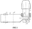
- a tractor unit forming the pulling vehicle 1 and a semi-trailer 2 forming the towed vehicle are connected by a coupling device in the form of a fifth wheel 3 attached to the tractor unit 1, the top view of which is approximately horseshoe-shaped, which forms a fifth wheel coupling plate 4 around itself the longitudinal axis 5 extending in the direction of travel together with the tractor unit 1 relative to the semitrailer 2, on the other hand together with the semitrailer 2 can be pivoted about a transverse axis 6 relative to the tractor unit, so that inadmissibly high bending stresses of the fifth wheel coupling plate 4 on uneven terrain are avoided, particularly in the illustrated 90th ° position of tractor 1 and semitrailer 2 when cornering when the rear wheel axle 7 of the semitrailer 2 is higher or lower than the rear wheel axle 8 of the tractor unit 1.
- Your fifth wheel plate 4 has an insertion slot 9 for a kingpin 10.
- the kingpin 10 is fastened to a flat semi-trailer plate 12 forming the other fifth wheel, e.g. welded, which in turn is attached to the semi-trailer 2 relative to the latter about the longitudinal axis 5 pivotable.
- the insertion slot 9 has at its inner (front in the direction of travel) an indentation 13 with a shoulder 14 forming the bottom of the indentation, the underside 15 of which lies deeper than the underside 16 of the coupling plate 4 and is of spherical design.
- An approximately horseshoe-shaped wear ring 17 is interchangeably fastened in the recess 13 by means of screws 18 (FIG. 2) on the shoulder 14.
- the wear ring 17 protrudes radially inwards over the edge of the shoulder 14 while maintaining a clearance 19 between the wear ring 17 and the kingpin 10.
- the inner edges 20, 21 of the wear ring are chamfered. But they can also be rounded. In addition, it is possible to round off the entire contact surface A for the kingpin.
- the contact side of the fifth wheel plate 4 for the semi-trailer plate 12 is convex towards the semi-trailer plate, namely in that it slopes conically in an area 22 outside a largely flat contact area 23 adjacent to the insertion slot 9 for the semi-trailer plate 12.
- the entire contact side of the fifth wheel coupling plate 4 can be curved or curved toward the semi-trailer plate 12.
- a locking hook 24 for engagement in an annular groove 25 at the lower end of the kingpin 10 "floating" on the fifth wheel coupling plate 4.
- the "floating" storage arises there by that the locking hook 24 according to FIG. 7 is mounted on only one bearing pin 26 which is guided through a slot 27 in the locking hook 24 with a relatively large, all-round play.
- the locking hook 24 can therefore also be pivoted about the longitudinal axis 5 and the transverse axis 6 within the scope of the game between the elongated hole 27 and the bearing pin 26.
- the locking hook 24 serves to secure the kingpin 10, which in turn is secured against rotation about the bearing pin 26 from the position shown by a transversely displaceable locking bolt 28 (FIGS. 2 and 7).
- the fifth wheel plate 4 is also pivotally mounted on two lateral bearing blocks 34 attached to the tractor unit 1 about bearing bolts 35, whose longitudinal central axis coincides with the transverse axis 6, relative to the tractor unit 1, the bearing bolts 35 being supported by rubber-elastic bearing sleeves 36 and vertical walls 37, 38 the bottom of the clutch plate 4 are passed.
- the bearing sleeves 36 are in turn arranged in transverse bores 39 of the bearing blocks 34.
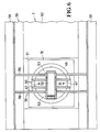
- the kingpin 10 is provided with a flange 46 which is fastened by means of screws 47 to the bottom of a receiving plate 49 welded to the edge of an opening 48 in the semitrailer plate 12.
- a receiving plate 49 welded to the edge of an opening 48 in the semitrailer plate 12.
- two parallel cross plates 50 ver tical attached.
- a bearing bush 51 is fixed, in which a hinge pin 52 is slidably mounted.
- the protruding from the bearing bush 51 end portions of the hinge pin 52 are in two further, aligned with the bearing bush 51 bearing bushes 53, 53 'of a bearing block 55 and axially secured.
- the bearing bushes 53 are fastened to two parallel transverse walls 56 of the bearing block 55 and the transverse walls 56 vertically under a horizontal support plate 57 and together with this between two double-T-shaped supports 58 of the chassis 59 of the trailer 59 extending in the direction of travel 45, the tapers forward in the present case into a rigid drawbar.
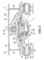
- the transverse walls 56 have in their lower edge a recess 60 (see FIGS. 3 and 4) which overlaps the receiving plate 40 with play for the relative transverse oscillation of the receiving plate 49 and the semitrailer 2 about the hinge pin 52 or the longitudinal axis 5.
- the semitrailer plate 12 lies in an opening 61 in the floor 62 of the chassis 59 and is somewhat lower than the floor 62, a lateral play being provided between the edge of the opening 61 and the semitrailer plate 12 for the transverse oscillation.
- Two cross-members U-shaped in cross-section 63 connect the supports 58, but are omitted in FIG. 6 to simplify the illustration.
- the cross plates 50 are connected to the bearing bush 51 and the receiving plate 49 and the transverse walls 56 to the bearing bushes 53, 53 'of the support plate 57 and the supports 58, preferably by welding.
- the semitrailer 2 and the fifth wheel 3 assume the relative position shown in FIG. 3.
- the semitrailer plate 12 initially maintains the position shown relative to the fifth wheel plate 4.
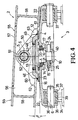
- the underside of the semitrailer 2 or the one support 58 is enclosed increasing angle of inclination ⁇ finally in the conical area 22 of the fifth wheel plate 4 with at least one side edge of the opening 61, as shown in FIG. 4.
- the semitrailer plate 12 lies on the flat contact area 23 of the upper side of the fifth wheel plate 4, and the locking hook 24 has a vertical distance from the spherical lower side 15 of the shoulder 14, as is shown in FIG. 3.
- the semitrailer plate 12 fastened to the semitrailer 2 can also be inclined about the longitudinal axis 5 together with the kingpin 10.
- the kingpin 10 is raised and pivoted, with its lower collar 40 engaging the underside of the locking hook 24 and also pivoting it until the locking hook 24 engages the spherical underside 15 of the shoulder 14.
- the underside of the semitrailer 2 in the conically sloping region 22 of the fifth wheel plate 4 can at least continue to line up with line contact between the underside of the semitrailer 2 and the fifth wheel plate 4, whereby in practice a surface contact occurs due to a certain elastic deformation and the bevelled edges 20 , 21 of the wear ring 17 result in a particularly large swivel angle range. Since the inclined position of the semitrailer 2 relative to the fifth wheel plate 4 generally only lasts for a short time, the higher surface pressure between the underside of the semitrailer 2 and the plate 4 caused by the line contact also only lasts for a short time.
- a fifth wheel plate with a flat top can be used if necessary and yet a sufficient range of inclination or swiveling angles ß around the longitudinal axis to the bottom or an edge of the Underside of the semitrailer 2 can be reached at the top of the fifth wheel plate.
- the swivel angle range ⁇ (FIG. 4) can be increased further without increasing the distance between the semitrailer 2 and fifth wheel plate 4, with a correspondingly larger angle of inclination of the conical region 22 of the fifth wheel plate 4.
- Modifications of the illustrated embodiment can consist, for example, in that the fifth wheel plate is flat and the fifth wheel plate is convex on its side facing the fifth wheel plate, for example, just like the fifth wheel plate 4 or conical over its entire surface or only curved in an outer edge region.
- the fifth wheel coupling plate 4 can alternatively be convex in such a way that it is not conical in the edge region 22, but curved or conical or curved over its entire surface.
Landscapes
- Engineering & Computer Science (AREA)
- Chemical & Material Sciences (AREA)
- Combustion & Propulsion (AREA)
- Transportation (AREA)
- Mechanical Engineering (AREA)
- Vehicle Cleaning, Maintenance, Repair, Refitting, And Outriggers (AREA)
- Handcart (AREA)
Applications Claiming Priority (2)
| Application Number | Priority Date | Filing Date | Title |
|---|---|---|---|
| DE19873741276 DE3741276A1 (de) | 1987-12-05 | 1987-12-05 | Kupplungseinrichtung |
| DE3741276 | 1987-12-05 |
Publications (2)
| Publication Number | Publication Date |
|---|---|
| EP0319765A2 true EP0319765A2 (fr) | 1989-06-14 |
| EP0319765A3 EP0319765A3 (fr) | 1990-06-20 |
Family
ID=6341958
Family Applications (1)
| Application Number | Title | Priority Date | Filing Date |
|---|---|---|---|
| EP88119378A Withdrawn EP0319765A3 (fr) | 1987-12-05 | 1988-11-22 | Dispositif de couplage |
Country Status (2)
| Country | Link |
|---|---|
| EP (1) | EP0319765A3 (fr) |
| DE (1) | DE3741276A1 (fr) |
Cited By (4)
| Publication number | Priority date | Publication date | Assignee | Title |
|---|---|---|---|---|
| CN103950477A (zh) * | 2014-05-05 | 2014-07-30 | 中国重汽集团湖北华威专用汽车有限公司 | 一种半挂运输车的活动牵引板装置 |
| WO2015055513A1 (fr) * | 2013-10-17 | 2015-04-23 | Jochen Meister | Véhicule de transport à chenilles |
| IT201600093812A1 (it) * | 2016-09-19 | 2018-03-19 | Iveco Spa | Sistema di interconnessione tra un trattore ed un rimorchio |
| WO2026009256A1 (fr) * | 2024-07-04 | 2026-01-08 | Ramkrishna Forgings Limited | Bague d'usure pour unité d'accouplement de sellette d'attelage |
Families Citing this family (1)
| Publication number | Priority date | Publication date | Assignee | Title |
|---|---|---|---|---|
| CN115195894B (zh) * | 2022-03-21 | 2023-06-20 | 东风柳州汽车有限公司 | 一种鞍座和牵引卡车 |
Family Cites Families (6)
| Publication number | Priority date | Publication date | Assignee | Title |
|---|---|---|---|---|
| US2857174A (en) * | 1957-06-25 | 1958-10-21 | Pacific Car & Foundry Co | Fifth-wheel assembly |
| BE551799A (fr) * | 1957-12-18 | |||
| US2923560A (en) * | 1958-03-24 | 1960-02-02 | Butler Manufacturing Co | Adjustable kingpin for upper rocking fifth wheel |
| FR1187462A (fr) * | 1958-12-23 | 1959-09-11 | Amortisseur redresseur d'oscillation pour attelage de semi-remorque avec sellette d'appui cylindrique | |
| DE2806543C2 (de) * | 1978-02-16 | 1982-12-23 | Walter Vetter Gmbh & Co, 7012 Fellbach | Anlenkung des Nachläufers eines Gelenkwagenzuges |
| DE2825941A1 (de) * | 1978-06-14 | 1980-01-03 | Scheuerle Fahrzeugfabrik Willy | Sattel-auflagevorrichtung zur kupplung eines sattel-schleppfahrwerkes mit einer sattelzugmaschine |
-
1987
- 1987-12-05 DE DE19873741276 patent/DE3741276A1/de active Granted
-
1988
- 1988-11-22 EP EP88119378A patent/EP0319765A3/fr not_active Withdrawn
Cited By (5)
| Publication number | Priority date | Publication date | Assignee | Title |
|---|---|---|---|---|
| WO2015055513A1 (fr) * | 2013-10-17 | 2015-04-23 | Jochen Meister | Véhicule de transport à chenilles |
| CN103950477A (zh) * | 2014-05-05 | 2014-07-30 | 中国重汽集团湖北华威专用汽车有限公司 | 一种半挂运输车的活动牵引板装置 |
| IT201600093812A1 (it) * | 2016-09-19 | 2018-03-19 | Iveco Spa | Sistema di interconnessione tra un trattore ed un rimorchio |
| WO2018051320A1 (fr) * | 2016-09-19 | 2018-03-22 | Iveco S.P.A. | Système d'interconnexion entre un tracteur et une remorque |
| WO2026009256A1 (fr) * | 2024-07-04 | 2026-01-08 | Ramkrishna Forgings Limited | Bague d'usure pour unité d'accouplement de sellette d'attelage |
Also Published As
| Publication number | Publication date |
|---|---|
| DE3741276C2 (fr) | 1993-04-22 |
| EP0319765A3 (fr) | 1990-06-20 |
| DE3741276A1 (de) | 1989-06-15 |
Similar Documents
| Publication | Publication Date | Title |
|---|---|---|
| EP0544727A1 (fr) | Vehicule. | |
| DE2950121C2 (de) | Aus Zugfahrzeug und Anhänger bestehender Lastzug | |
| EP0132702B1 (fr) | Attelage entre un véhicule tracteur et une remorque en particulier une remorque à essieu unique | |
| EP3996978B1 (fr) | Agencement adaptateur pour un agencement de remorque | |
| EP0156985B1 (fr) | Attelage entre véhicule tracteur et remorque, en particulier pour remorque à essieu unique | |
| DE3316128A1 (de) | Anhaengevorrichtung fuer landwirtschaftliche schlepperfahrzeuge | |
| DE3445741C2 (de) | Aus Einzelfahrzeugen zusammengesetzter Zug für Straßen- und Schienenverkehr | |
| EP0319766A2 (fr) | Dispositif de couplage | |
| EP0319765A2 (fr) | Dispositif de couplage | |
| EP3398842B1 (fr) | Diabolo pour système de support de selle | |
| DE202009016346U1 (de) | Hinterachslenkvorrichtung für drehschemelgelenkte Anhängefahrzeuge, insbesondere für Schneidwerkswagen | |
| CH637579A5 (de) | Verfahren und vorrichtung zur erzielung enger wendekreise bei einem aus einem zugfahrzeug und einem anhaengerfahrzeug bestehenden gleiskettenlastenzug. | |
| DE3328123A1 (de) | Lastzug mit einer lenkung fuer das anhaengerfahrzeug | |
| DE102020115469B4 (de) | Dolly-Anhänger, Zug-Gespann mit einem solchen Dolly-Anhänger sowie Verfahren zum Betreiben eines solchen Zug-Gespannes | |
| DE3004885C2 (de) | Lastzug | |
| DE3531252C2 (fr) | ||
| DE102007006265A1 (de) | Sattelzugmaschine eines Sattelkraftwagens | |
| DE102013112635A1 (de) | Schleppzeug mit einem Schleppfahrzeug und mindestens einem geschleppten Anhänger | |
| DE2119013C3 (de) | Kupplungsanordnung für ein Fahrzeug nach Art eines Sattelschleppers | |
| DE707314C (de) | Lenkbare Achse fuer gezogene Fahrzeuge | |
| AT314989B (de) | Zweiachs-Nachläufer für dem Langgut-, insbesondere Holztransport dienende Lastfahrzeuge | |
| EP0282922B1 (fr) | Train routier comprenant un véhicule directeur à essieu unique et une remorque de transport à plusieurs essieux | |
| AT378747B (de) | Sattelzugfahrzeug | |
| DE2833931A1 (de) | Anhaenger mit absenkbarer laderampe | |
| DE3400878A1 (de) | Lastkraftfahrzeug mit kuppelbarem einachsanhaenger |
Legal Events
| Date | Code | Title | Description |
|---|---|---|---|
| PUAI | Public reference made under article 153(3) epc to a published international application that has entered the european phase |
Free format text: ORIGINAL CODE: 0009012 |
|
| AK | Designated contracting states |
Kind code of ref document: A2 Designated state(s): AT BE CH DE ES FR GB IT LI NL SE |
|
| PUAL | Search report despatched |
Free format text: ORIGINAL CODE: 0009013 |
|
| AK | Designated contracting states |
Kind code of ref document: A3 Designated state(s): AT BE CH DE ES FR GB IT LI NL SE |
|
| 17P | Request for examination filed |
Effective date: 19900802 |
|
| 17Q | First examination report despatched |
Effective date: 19910402 |
|
| STAA | Information on the status of an ep patent application or granted ep patent |
Free format text: STATUS: THE APPLICATION IS DEEMED TO BE WITHDRAWN |
|
| 18D | Application deemed to be withdrawn |
Effective date: 19920428 |