EP0319840A2 - Zielscheibe für das Wurfpfeilenspiel - Google Patents
Zielscheibe für das Wurfpfeilenspiel Download PDFInfo
- Publication number
- EP0319840A2 EP0319840A2 EP88120016A EP88120016A EP0319840A2 EP 0319840 A2 EP0319840 A2 EP 0319840A2 EP 88120016 A EP88120016 A EP 88120016A EP 88120016 A EP88120016 A EP 88120016A EP 0319840 A2 EP0319840 A2 EP 0319840A2
- Authority
- EP
- European Patent Office
- Prior art keywords
- target
- base
- members
- target according
- ribs
- Prior art date
- Legal status (The legal status is an assumption and is not a legal conclusion. Google has not performed a legal analysis and makes no representation as to the accuracy of the status listed.)
- Granted
Links
Images


Classifications
-
- A—HUMAN NECESSITIES
- A63—SPORTS; GAMES; AMUSEMENTS
- A63B—APPARATUS FOR PHYSICAL TRAINING, GYMNASTICS, SWIMMING, CLIMBING, OR FENCING; BALL GAMES; TRAINING EQUIPMENT
- A63B65/00—Implements for throwing ; Mechanical projectors, e.g. using spring force
-
- F—MECHANICAL ENGINEERING; LIGHTING; HEATING; WEAPONS; BLASTING
- F41—WEAPONS
- F41J—TARGETS; TARGET RANGES; BULLET CATCHERS
- F41J3/00—Targets for arrows or darts, e.g. for sporting or amusement purposes
- F41J3/0009—Dartboards
- F41J3/0033—Dartboards for use with safety darts
- F41J3/0042—Dartboards for use with safety darts having perforations for receiving blunt tip darts
-
- F—MECHANICAL ENGINEERING; LIGHTING; HEATING; WEAPONS; BLASTING
- F41—WEAPONS
- F41J—TARGETS; TARGET RANGES; BULLET CATCHERS
- F41J3/00—Targets for arrows or darts, e.g. for sporting or amusement purposes
- F41J3/0009—Dartboards
- F41J3/0061—Target faces
- F41J3/0066—Segmentation of conventional target faces
Definitions
- This invention relates to a dart game target construction of the kind having a plurality of individual, independently movable target sections together forming a target of circular or other geometric configuration and wherein the individual sections are spaced from one another and maintained in assembled relation by a retainer having spaced ribs interposed between and reacting with adjacent target sections wholly internally of the target's outer surface.
- dart game targets have been of the kind employing a circular, mat-like body having a spider composed of concentric circular and radial wire strands overlying the body and dividing the target surface into a plurality of areas having various score values.
- Darts have been provided for use with such targets and such darts have been equipped with sharp, metal tips that can be embedded in the target.
- the wire strands of the spider have been of relatively small diameter, thereby offering little likelihood that a dart tip will rebound as a result of striking the spider.
- dart games More recently, electronically scored dart games have become popular. Such games utilize darts having flexible, plastic tips and a target composed of displaceable target sections having closely spaced openings in their outer surfaces for the accommodation of a dart tip.
- a typical dart and target of this kind are disclosed in Jones et al United States patent No. 4,057,251.
- the target is composed of a plurality of individual target sections maintained in assembled relation by means of a spider-like retainer having circular and radial dividers or ribs.
- the target sections overlie a base and between the base and the target sections is an electrical switch.
- the target sections are biased in a direction away from the base so that, whenever a thrown dart strikes a target section, the latter is displaced toward the base a distance sufficient to operate the associated switch and actuate a scoring mechanism. Since the target sections are biased in a direction away from the base, some means must be provided to limit their movement away from the base while, at the same time, enabling sufficient movement toward the base to effect operation of the switches.
- the circular and radial ribs of the retaining spider have smooth divider walls accommodated between adjacent sections and each such wall terminates at its outer edge in a barb-like extension which overlies the edges of the adjacent target sections and therefore limits the extent of movement of such sections away from the base under the influence of the biasing means. Since some portion of each target section underlies the retaining barb of the rib, a relatively wide space necessarily exists between the outer or exposed surfaces of adjacent target sections in which the tip of the dart cannot be accommodated in an opening of either section. Consequently, the tip of a dart striking the retaining barb either rebounds, resulting in a miss, or is deflected to one side or the other of the barb.
- the width of the retaining barbs it is desirable to taper the exposed outer surface thereof. Normally, the outer surface tapers from its center toward both opposite edges. To avoid excessive projection of the barbs beyond the outer faces of the target sections, the included angle between a barb's tapering surfaces is relatively large. Thus, when a dart tip strikes a barb, the tip will be deflected. On occasions the angle of deflection may be such that the dart tip is unable to enter a tip-accommodating opening, thereby resulting in a miss.
- the spider walls of conventional constructions inwardly of the retaining barbs have been made quite thin.
- the larger difference in thickness between the barbs and the spider walls can result in an inwardly concave warping of the spider which, unless counteracted, can result in the presence of an inconsistent clearance between a target section and the biasing means or no such clearance at all.
- the sole retaining means for target sections of such conventional constructions constitutes the overlying barb-like retainers at the exposed ends of the spider ribs, warpage can cause forces to be exerted on the target sections which will either prevent free movement of such sections toward and away from the base, or cause excessive clearance or looseness of such sections with resulting imperfect scoring.
- a principal objective of the present invention is to provide a target construction adapted for use with soft tipped darts and electronic scoring mechanisms and which overcomes the disadvantages of previously known constructions.
- a target suitable for use in an electronically scored, soft tipped dart game and constructed in accordance with the invention comprises a base on which is secured a retaining frame or spider comprising concentric circular dividers or ribs interconnected by radial dividers or ribs.
- the ribs are interposed between individual target members which are movable independently of one another toward and away from the base.
- Each target member has an inner face confronting the base and an outer, exposed face provided with closely spaced, inwardly tapering openings of such size as to receive the tapering tip of a dart.
- a pressure sensitive, electrical matrix switch of known kind Overlying the base and interposed between the latter and the inner faces of the target members are a pressure sensitive, electrical matrix switch of known kind and a resilient biasing sheet which underlies the inner faces of the target members in a position to bias the latter in a direction away from the base following their being struck by a dart.
- each target member has lateral projections adjacent its inner face that extend into the space between the biasing sheet and the adjacent circular or radial rib and underlie the latter with a slight clearance therebetween.
- the ribs and the projections thus cooperate to limit movement of the target members in a direction away from the base under the influence of the biasing means, but permit movement of the members toward the base when they are struck by a thrown dart so as to operate the switch and a scoring mechanism actuated thereby.
- the outer ends of the spider ribs are not barbed, but are tapered to minimize the possibility of a dart's rebounding should its tip strike the rib.
- no part of any circular or radial divider rib overlies any part of a target member. Since no divider rib has a thick barb at its outer edge, warping due to large differences in thickness is avoided.
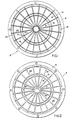
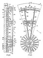
- a dart game target constructed in accordance with the disclosed embodiment is designated generally by the reference character 1 ( Figures 3 and 4) and comprises a retaining frame or spider 2, a plurality of radially spaced, circumferentially extending, segment shaped target members 3, 4, 5, and 6, an annular outer bullseye member 7, and a cylindrical inner bullseye member 8.
- the retaining spider 2 comprises a mounting flange 9 provided with screw-accommodating openings 10.
- the spider may be secured to a backboard or base 11 formed of wood, plastic, or other suitable material by means of a plurality of screws 12.
- the spider Radially inward of the mounting flange 9 the spider includes a plurality of concentric circular dividers or ribs 13, 14, 15, 16, and 17 that are spaced at various radial distances from a common center 18 ( Figure 4).
- Each of the circular ribs is joined by a plurality of circumferentially spaced, radially extending dividers or ribs 19 each of which has a radially inner section 20 extending outwardly from the innermost ring 17 to the next adjacent rib 16.
- the circular ribs 16 and 15 are joined by a section 21 of each radial rib 19 and the circular ribs 15 and 14 are joined by another section 22 of each radial rib 19.
- the circular ribs 14 and 13 are joined by a section 23 of each radial rib 19.
- each of the circular ribs 13-17 tapers to a sharp edge 24.
- the outer or exposed surface of each of the radial ribs 19 similarly tapers to a sharp edge 25.
- the circular and radial ribs of the spider divide the area thereof into a plurality of open spaces adapted to be occupied by the target members.
- This target member also is shown in Figure 9 and comprises a body 27 having an exposed outer face 28.
- the entire area of the face 28 is provided with a plurality of closely spaced, inwardly tapered openings 29.
- Each of the openings 29 communicates with a cavity 30 inwardly of the surface 28.
- Each member 3 has an inner end or face 31 that is adapted to confront the base 11 and is provided with a plurality of coplanar foot elements 32 which project beyond the face 31. Adjacent the face 31 the member 3 is provided along the radially inner sides thereof with a lateral projection 33. At each of its opposite ends the member 3 has a lateral projection 34. As is best shown in Figure 5, the projection 34 at one end of the target member is located at the radially inner side of the member whereas the projection 34 at the opposite end is located at the radially outer edge of the member. Thus, the projections at opposite ends of the member 3 are staggered.
- each member 4 comprises a body 36 having an outer exposed face 37 the entire area of which is provided with a plurality of openings 38 corresponding in size to the openings 29.
- the body 36 has a cavity 39 therein with which each of the openings 38 communicates.
- the body 36 has an inner face 40 from which two pairs of lateral projections 41 extend and, as is best shown in Figure 5, the projections along one side edge of the body 36 are staggered with respect to the projections along the opposite side of the segment.
- Two pairs of foot elements 42 like the elements 32 extend rearwardly from the inner face of the segment 4.
- each member 5 has a body 43 having an outer face 44 provided with a plurality of openings 45 like the openings 29.
- the body 43 also has a cavity 46 in communication with the openings 45. From the inner face of the body 43 extend three projecting foot elements 47 best shown in Figure 5.
- the member 5 has at its radially inner edge a lateral projection 48 which extends the full length of the member, and at the radially outer edge of the member 5 is a lateral partial projection 49 which extends radially outwardly.
- the member 6 has a body 51 having an outer surface 52 provided with openings 53 like the openings 29 and which communicate with a cavity 54.
- the inner face of the body 51 is provided with four projecting foot elements 55, two along one side, and two along the other.
- the member 6 also is provided along its opposite sides with two pairs of lateral projections 56, the projections along one side of the segment being staggered with respect to the projections along the other side, as is best shown in Figure 5.
- a bullseye assembly 57 composed of the outer, annular member 7 and the inner, cylindrical member 8.
- the two members 7 and 8 are best shown in Figure 7, and for purposes of clarity the members 7 and 8 are shown in separated condition. Such members are shown in assembled condition in Figure 4.
- the member 7 comprises an annular body 58 having an outer, exposed surface 60 through which extend a plurality of openings 61 like the openings 29.
- the body 58 also includes an annular sleeve 62 having a tapered outer edge 63 and a cylindrical bore 64.
- the body 58 has a cavity 65 in communication with the openings 61.
- the sleeve 62 projects into the cavity, but terminates in a free end 66 that is spaced from the inner face 67 of the body 58. Adjacent the inner face 67 the body 58 is provided with four circumferentially spaced, radially extending projections 68 and from the face 67 of the body 58 project four equally spaced foot elements 69.
- the inner bullseye member 8 comprises a cylindrical core or body 70 having an outer face 71 provided with openings 72 like the openings 29 and which communicate with a cavity 73 ( Figure 4) that extends to the inner face 74 of the member 8. Adjacent the face 74 of the member 8 is an annular, lateral flange 75 forming a shoulder 76.
- the diameter of the outer bullseye member 7 is such as to enable it to be accommodated freely within the circular space formed by the innermost circular rib 17.
- the inner periphery of the rib 17 is provided with one or more circumferen tially spaced, axially extending keys 77 that may be accommodated in correspondingly spaced keyways (not shown) formed in the outer surface of the body 58 so as to preclude relative rotation between the outer bullseye member 7 and the circular rib 17.
- Similar keys and keyways may be provided, if desired, on the inner surface of the sleeve 62 and the outer surface of the body 70 of the inner bullseye member 8.
- the diameter of the cylindrical body 70 of the inner bullseye member 8 is such as to enable it freely to be accommodated within the sleeve 62, and the relative dimensions of the sleeve 62 and the flange 75 are such that the inner end 66 of the sleeve 62 may seat on the shoulder 76 of the flange 75 when the members 7 and 8 are assembled.
- two or three circumferentially spaced foot elements 78 fixed to the inner face of the flange 75 will project from the latter and be coplanar with the foot elements 69 of the bullseye member 7.
- the base member 11 may be provided with a counterbore 80 ( Figure 4) at the bottom of which is positioned a pressure sensitive, electrical matrix switch 81 of known construction having a plurality of spaced contacts and wiring (not shown) for connection to a source of electrical power.
- the contacts are arranged to underlie the switch-actuating feet of the respective target members.
- a biasing member 82 such as a resiliently compressible, elastomeric sheet of rubber or rubber-like material.
- the areas of the counterbore 80, the switch 81, and the biasing member correspond substantially to that of the spider 2 radially inward of the mounting flange 9.
- the base 11, the switch 81, and the biasing member 82 are arranged in overlying relation, following which the target members are moved into the correspondingly shaped spaces formed in the spider 2 between the circular and radial ribs.
- the target members are fitted into their respective spaces from the under side of the spider, or by movement of the members from left to right as viewed in Figure 6.
- the mounting flange 9 may be secured to the base 11 by means of the screws 12.
- the left-hand, or inner, ends of all of the radial and circular ribs terminate short of the plane of the inner surface of the mounting flange 9, thereby providing between the biasing member 82 and the inner ends of the ribs a space or gap 83 best shown in Figure 6.
- the depth of the gap 83 is greater than the thickness of the lateral retainer projections 33, 34, 47, 48, 56, of the respective target members 3, 4, 5, and 6, and such gap also has a depth greater than the thickness of the peripheral retainer projections 68 forming part of the outer bullseye member 7.
- the respective projections on the target members may extend into the gap 83 to underlie and seat on the terminal ends of the respective circular and radial ribs.
- the thickness of the lateral projections is such that a clearance 84 ( Figure 6) normally exists between the inner surfaces of the projections and the free ends of the various foot elements 32, 42, 47, and 55 of the respective target segments 3, 4, 5, and 6, and the foot elements 69 and 78 of the bullseye members 7 and 8, respectively.
- the length of each of the foot elements is such that it substantially spans the clearance 84 and confronts the surface of the biasing member 82 with a small gap 86 ( Figure 6) therebetween so as normally not to subject the biasing member to compression.
- the retaining projections along one side of a target member are staggered relative to the projections along the opposite side.
- This construction enables two adjacent members on opposite sides of a single rib to underlie that rib without interfering with one another. It also enables the radial thickness of the ribs to be kept to a minimum.
- the apparatus is adapted for use with a dart (not shown) having at its forward end a tapered, plastic, blunt tip of such size as to fit in any of the tip-accommodating openings formed in the respective target members.
- a dart (not shown) having at its forward end a tapered, plastic, blunt tip of such size as to fit in any of the tip-accommodating openings formed in the respective target members.
- the matrix switch 81 has pressure sensitive contacts confronting the respective foot elements so as to be operated in response to such movement of the target member.
- each opening has a uniform diameter or tapered bore 89 matching the taper of the dart tip, and terminating adjacent the outer face of its target member in a mouth having an outwardly diverging side wall 90 for guiding a dart tip into the bore 89.
- the spacing between adjacent openings is small, as a consequence of which the mouths of adjacent openings inwardly of the side edges of the target members overlap one another.
- the biasing member 82 When the force generated by the energy of a thrown dart's striking the target member has been dissipated, the biasing member 82 will expand, thereby returning the displaced target member to its original position.
- the movements of the target members toward and away from the base are guided by the smooth, confronting sides of the target members and the adjacent ribs.
- the construction of the bullseye assembly 57 is such that, regardless of whether a dart strikes the outer member 7 or the inner member 8, only the struck member will be displaced to effect closing of the associated switch.
- Retention of the individual target members in relatively movable, assembled relation with the spider is achieved wholly internally of the assembly, and at a level between the outer and inner faces of the target members, by the engagement of the lateral projections of the various target members with the inner surfaces of the spider ribs. It thus is possible to taper the outer or free ends of the ribs to a fine edge, as is shown particularly well in Figure 6, thereby minimizing the possibility that a dart's striking a rib will cause the dart to rebound. Further, the included angle between opposite tapered surfaces can be relatively small, thereby maximizing the likelihood that a dart's tip, upon striking a rib, will be deflected into one of the tip-accommodating openings.
- the ribs can be made quite thin, thereby maximizing the number of dart tip-accommodating openings that can be provided in the segments.
Landscapes
- Engineering & Computer Science (AREA)
- General Engineering & Computer Science (AREA)
- Mechanical Engineering (AREA)
- Health & Medical Sciences (AREA)
- General Health & Medical Sciences (AREA)
- Physical Education & Sports Medicine (AREA)
- Aiming, Guidance, Guns With A Light Source, Armor, Camouflage, And Targets (AREA)
- Toys (AREA)
- Pinball Game Machines (AREA)
- Pharmaceuticals Containing Other Organic And Inorganic Compounds (AREA)
- Acyclic And Carbocyclic Compounds In Medicinal Compositions (AREA)
- Medicines Containing Material From Animals Or Micro-Organisms (AREA)
- Coloring Foods And Improving Nutritive Qualities (AREA)
- Switch Cases, Indication, And Locking (AREA)
Priority Applications (1)
| Application Number | Priority Date | Filing Date | Title |
|---|---|---|---|
| AT88120016T ATE85698T1 (de) | 1987-12-11 | 1988-11-30 | Zielscheibe fuer das wurfpfeilenspiel. |
Applications Claiming Priority (2)
| Application Number | Priority Date | Filing Date | Title |
|---|---|---|---|
| US131950 | 1987-12-11 | ||
| US07/131,950 US4836556A (en) | 1987-12-11 | 1987-12-11 | Dart game target construction |
Publications (4)
| Publication Number | Publication Date |
|---|---|
| EP0319840A2 true EP0319840A2 (de) | 1989-06-14 |
| EP0319840A3 EP0319840A3 (en) | 1990-09-05 |
| EP0319840B1 EP0319840B1 (de) | 1993-02-10 |
| EP0319840B2 EP0319840B2 (de) | 1995-05-17 |
Family
ID=22451742
Family Applications (1)
| Application Number | Title | Priority Date | Filing Date |
|---|---|---|---|
| EP88120016A Expired - Lifetime EP0319840B2 (de) | 1987-12-11 | 1988-11-30 | Zielscheibe für das Wurfpfeilenspiel |
Country Status (11)
| Country | Link |
|---|---|
| US (1) | US4836556A (de) |
| EP (1) | EP0319840B2 (de) |
| JP (1) | JPH0722609B2 (de) |
| KR (1) | KR920000311B1 (de) |
| AT (1) | ATE85698T1 (de) |
| AU (1) | AU600637B2 (de) |
| CA (1) | CA1309430C (de) |
| DE (1) | DE3878426T2 (de) |
| ES (1) | ES2039571T5 (de) |
| GB (1) | GB2213394B (de) |
| NZ (1) | NZ227254A (de) |
Cited By (5)
| Publication number | Priority date | Publication date | Assignee | Title |
|---|---|---|---|---|
| EP0645598A3 (de) * | 1990-02-13 | 1995-08-02 | Nsm Ag | Wurfpfeil-Scheibe. |
| DE4429894A1 (de) * | 1994-08-25 | 1996-02-29 | Stefan Reichert | Zielscheibe für Geschosse, insbesondere für Wurfgeschosse |
| FR2744209A1 (fr) * | 1996-01-31 | 1997-08-01 | Nsm Ag | Cible pour des projectiles, notamment pour des projectiles lances |
| CN1058081C (zh) * | 1995-07-14 | 2000-11-01 | 名世电子企业股份有限公司 | 飞标靶的双靶心结构 |
| GB2606708A (en) * | 2021-05-10 | 2022-11-23 | Unicorn Products Ltd | Dartboard spider |
Families Citing this family (18)
| Publication number | Priority date | Publication date | Assignee | Title |
|---|---|---|---|---|
| DE3784860D1 (de) * | 1986-12-05 | 1993-04-22 | Ciba Geigy Ag | Verbessertes verfahren zur transformation von pflanzlichen protoplasten. |
| US4924922A (en) * | 1988-10-17 | 1990-05-15 | Black & Decker, Inc. | Brew through lid for coffee maker |
| DE4042559C2 (de) * | 1990-02-13 | 1996-08-29 | Nsm Ag | Wurfpfeil-Scheibe |
| US4976441A (en) * | 1990-02-15 | 1990-12-11 | Samuel Kim | Single piece molded housing and spider for electronic dartboard |
| US5116063A (en) * | 1991-02-20 | 1992-05-26 | Arachnid, Inc. | Dart game with expanded scoring technique |
| US5193817A (en) * | 1991-12-24 | 1993-03-16 | Francis Pan | Dart game |
| ATE203596T1 (de) * | 1994-06-21 | 2001-08-15 | Arino Miguel Angel Quetglas | Beleuchtetes wurfpfeilziel |
| US5482291A (en) * | 1995-04-25 | 1996-01-09 | Merit Industries, Inc | Dart board apparatus with independently supported double bull segment |
| GB2300818A (en) * | 1995-05-15 | 1996-11-20 | Lu Kuo Hui | Dart board assembly |
| US5848792A (en) | 1997-06-05 | 1998-12-15 | Valley Recreation Products Inc. | Target construction |
| TW333329U (en) * | 1997-08-01 | 1998-06-01 | kun-lin Zhuo | Improved structure of a dart board |
| DE29800907U1 (de) * | 1998-01-20 | 1998-03-05 | Yiu, Chih-Hao, Taichung | Dartscheibe |
| TW362766U (en) * | 1998-09-09 | 1999-06-21 | kun-lin Zhuo | Improvement for constitution of target block of dart target |
| GB2353483B (en) * | 2000-04-17 | 2001-07-11 | Yiu Chih Hao | Noise reduction dart board |
| TW421262U (en) * | 2000-04-29 | 2001-02-01 | Jang Wen Fang | Rebound target structure for dartboard |
| TW421263U (en) * | 2000-04-29 | 2001-02-01 | Jang Wen Fang | Target body exchange structure for dartboard |
| JP2009061000A (ja) * | 2007-09-05 | 2009-03-26 | Taito Corp | ダーツ、ダーツ用アタッチメント、ダーツ遊技機及びダーツ遊技システム |
| USD760322S1 (en) * | 2014-08-21 | 2016-06-28 | Dustin Olin Shaw | Dart board face |
Family Cites Families (14)
| Publication number | Priority date | Publication date | Assignee | Title |
|---|---|---|---|---|
| FR474718A (fr) * | 1913-12-19 | 1915-03-04 | Erico Augusto De Oliveira | Cible électrique |
| US1286215A (en) * | 1918-04-12 | 1918-12-03 | Clarence H Brainard | Target apparatus. |
| GB520021A (en) * | 1939-05-15 | 1940-04-11 | Hector Fraser | Improvements in playing boards for darts and like games |
| GB644517A (en) * | 1948-04-23 | 1950-10-11 | Denis Frank Abbett | Improvements in or relating to indicators for score values set up on game apparatus,and to dartboards for use therewith |
| US3454276A (en) * | 1966-03-21 | 1969-07-08 | Wayne D Brenkert | Self-scoring dart game |
| US3729197A (en) * | 1971-03-01 | 1973-04-24 | D Swanson | Archery target having pressure sensitive score indicating bags |
| GB1333862A (en) * | 1971-04-24 | 1973-10-17 | Jenkins A | Apparatus for playing a game |
| GB1370609A (en) * | 1971-10-21 | 1974-10-16 | Sporting Automatics Ltd | Targets for electric games |
| US4057251A (en) * | 1976-05-10 | 1977-11-08 | Arachnid, Incorporated | Dart game with apertured target plates resiliently mounted |
| US4516781A (en) * | 1982-11-17 | 1985-05-14 | Industrial Design Electronic Associates, Inc. | Dart game with two microcomputers |
| US4561660A (en) * | 1983-11-14 | 1985-12-31 | Arachnid, Inc. | Dart machine with electronic matrix |
| US4586716A (en) * | 1984-04-17 | 1986-05-06 | Industrial Design Electronic Associates, Inc. | Double bullseye for dart game |
| IL77588A0 (en) * | 1986-01-14 | 1987-03-31 | Yeda Res & Dev | Agricultural preparations containing bacteria |
| US4706962A (en) * | 1986-05-27 | 1987-11-17 | Arachnid, Inc. | Dart board with target plates structured as discrete grids |
-
1987
- 1987-12-11 US US07/131,950 patent/US4836556A/en not_active Expired - Lifetime
-
1988
- 1988-11-30 ES ES88120016T patent/ES2039571T5/es not_active Expired - Lifetime
- 1988-11-30 AT AT88120016T patent/ATE85698T1/de not_active IP Right Cessation
- 1988-11-30 EP EP88120016A patent/EP0319840B2/de not_active Expired - Lifetime
- 1988-11-30 DE DE3878426T patent/DE3878426T2/de not_active Expired - Lifetime
- 1988-12-06 CA CA000585113A patent/CA1309430C/en not_active Expired - Lifetime
- 1988-12-07 GB GB8828514A patent/GB2213394B/en not_active Expired - Fee Related
- 1988-12-08 NZ NZ227254A patent/NZ227254A/xx unknown
- 1988-12-09 KR KR1019880016372A patent/KR920000311B1/ko not_active Expired
- 1988-12-09 AU AU26737/88A patent/AU600637B2/en not_active Ceased
- 1988-12-09 JP JP63311772A patent/JPH0722609B2/ja not_active Expired - Lifetime
Cited By (10)
| Publication number | Priority date | Publication date | Assignee | Title |
|---|---|---|---|---|
| EP0645598A3 (de) * | 1990-02-13 | 1995-08-02 | Nsm Ag | Wurfpfeil-Scheibe. |
| EP0648995A3 (de) * | 1990-02-13 | 1995-08-02 | Nsm Ag | Wurfpfeil-Scheibe. |
| EP0653602A3 (de) * | 1990-02-13 | 1995-08-02 | Nsm Ag | Wurfpfeil-Scheibe. |
| EP0648996A3 (de) * | 1990-02-13 | 1995-08-02 | Nsm Ag | Wurfpfeil-Scheibe. |
| EP0781974A3 (de) * | 1990-02-13 | 1997-07-09 | Nsm Aktiengesellschaft | Wurfpfeil-Scheibe |
| DE4429894A1 (de) * | 1994-08-25 | 1996-02-29 | Stefan Reichert | Zielscheibe für Geschosse, insbesondere für Wurfgeschosse |
| CN1058081C (zh) * | 1995-07-14 | 2000-11-01 | 名世电子企业股份有限公司 | 飞标靶的双靶心结构 |
| FR2744209A1 (fr) * | 1996-01-31 | 1997-08-01 | Nsm Ag | Cible pour des projectiles, notamment pour des projectiles lances |
| GB2606708A (en) * | 2021-05-10 | 2022-11-23 | Unicorn Products Ltd | Dartboard spider |
| GB2606708B (en) * | 2021-05-10 | 2025-09-17 | Unicorn Products Ltd | Dartboard spider |
Also Published As
| Publication number | Publication date |
|---|---|
| ES2039571T3 (es) | 1993-10-01 |
| KR920000311B1 (ko) | 1992-01-11 |
| CA1309430C (en) | 1992-10-27 |
| DE3878426T2 (de) | 1995-10-05 |
| JPH0722609B2 (ja) | 1995-03-15 |
| ATE85698T1 (de) | 1993-02-15 |
| KR890009431A (ko) | 1989-08-02 |
| GB8828514D0 (en) | 1989-01-11 |
| NZ227254A (en) | 1991-02-26 |
| EP0319840B1 (de) | 1993-02-10 |
| EP0319840B2 (de) | 1995-05-17 |
| GB2213394B (en) | 1991-12-18 |
| ES2039571T5 (es) | 1995-08-16 |
| US4836556A (en) | 1989-06-06 |
| GB2213394A (en) | 1989-08-16 |
| JPH01201276A (ja) | 1989-08-14 |
| EP0319840A3 (en) | 1990-09-05 |
| AU600637B2 (en) | 1990-08-16 |
| AU2673788A (en) | 1989-06-15 |
| DE3878426D1 (de) | 1993-03-25 |
Similar Documents
| Publication | Publication Date | Title |
|---|---|---|
| EP0319840B1 (de) | Zielscheibe für das Wurfpfeilenspiel | |
| US4635940A (en) | Dart board assembly for an electronic dart game | |
| US4057251A (en) | Dart game with apertured target plates resiliently mounted | |
| US4586716A (en) | Double bullseye for dart game | |
| US5718641A (en) | Golf club head that makes a sound when striking the ball | |
| WO1998016279A8 (en) | A football teaching aid | |
| JPS60122898A (ja) | 電子基盤を備えたダートゲーム機 | |
| US5613685A (en) | Automated dart board | |
| US4651998A (en) | Projectile target game with score keeping apparatus | |
| GB2314030A (en) | Electronic dart board | |
| US20040251631A1 (en) | Hammer striking game | |
| US5848792A (en) | Target construction | |
| GB2209959A (en) | Automatic-scoring dartboard | |
| US5482291A (en) | Dart board apparatus with independently supported double bull segment | |
| US6302809B1 (en) | Noise reduction dart board | |
| US6659465B2 (en) | Silent dart board | |
| US2200848A (en) | Sound producing device for a tap dancing shoe | |
| KR200345588Y1 (ko) | 전자 다트 게임기 | |
| JPH1147363A (ja) | パチンコ機の遊技釘及びその遊技釘を使用した遊技盤 | |
| GB2098077A (en) | A pinball gate device | |
| JP2538757Y2 (ja) | ゲーム機の押し釦スイッチ | |
| GB2114902A (en) | Marking grid for dartboard | |
| JPH08299542A (ja) | 弾球遊技機用釘機構 | |
| JP2002301253A (ja) | パチンコ遊技機 | |
| JPH07169371A (ja) | コントロールキー装置 |
Legal Events
| Date | Code | Title | Description |
|---|---|---|---|
| PUAI | Public reference made under article 153(3) epc to a published international application that has entered the european phase |
Free format text: ORIGINAL CODE: 0009012 |
|
| AK | Designated contracting states |
Kind code of ref document: A2 Designated state(s): AT BE CH DE ES FR GR IT LI LU NL SE |
|
| PUAL | Search report despatched |
Free format text: ORIGINAL CODE: 0009013 |
|
| AK | Designated contracting states |
Kind code of ref document: A3 Designated state(s): AT BE CH DE ES FR GR IT LI LU NL SE |
|
| 17P | Request for examination filed |
Effective date: 19900921 |
|
| 17Q | First examination report despatched |
Effective date: 19911009 |
|
| GRAA | (expected) grant |
Free format text: ORIGINAL CODE: 0009210 |
|
| AK | Designated contracting states |
Kind code of ref document: B1 Designated state(s): AT BE CH DE ES FR GR IT LI LU NL SE |
|
| PG25 | Lapsed in a contracting state [announced via postgrant information from national office to epo] |
Ref country code: LI Effective date: 19930210 Ref country code: CH Effective date: 19930210 |
|
| REF | Corresponds to: |
Ref document number: 85698 Country of ref document: AT Date of ref document: 19930215 Kind code of ref document: T |
|
| ITF | It: translation for a ep patent filed | ||
| REF | Corresponds to: |
Ref document number: 3878426 Country of ref document: DE Date of ref document: 19930325 |
|
| ET | Fr: translation filed | ||
| REG | Reference to a national code |
Ref country code: GR Ref legal event code: FG4A Free format text: 3007526 |
|
| PLBI | Opposition filed |
Free format text: ORIGINAL CODE: 0009260 |
|
| PG25 | Lapsed in a contracting state [announced via postgrant information from national office to epo] |
Ref country code: LU Free format text: LAPSE BECAUSE OF NON-PAYMENT OF DUE FEES Effective date: 19931130 |
|
| 26 | Opposition filed |
Opponent name: NOVO-INVEST CASINO DEVELOPMENT AKTIENGESELLSCHAFT Effective date: 19931109 |
|
| NLR1 | Nl: opposition has been filed with the epo |
Opponent name: NOVO-INVEST CASINO DEVELOPMENT AG. |
|
| EPTA | Lu: last paid annual fee | ||
| PGFP | Annual fee paid to national office [announced via postgrant information from national office to epo] |
Ref country code: GR Payment date: 19941027 Year of fee payment: 7 |
|
| PGFP | Annual fee paid to national office [announced via postgrant information from national office to epo] |
Ref country code: SE Payment date: 19941031 Year of fee payment: 7 |
|
| PGFP | Annual fee paid to national office [announced via postgrant information from national office to epo] |
Ref country code: CH Payment date: 19941124 Year of fee payment: 7 |
|
| PGFP | Annual fee paid to national office [announced via postgrant information from national office to epo] |
Ref country code: BE Payment date: 19941128 Year of fee payment: 7 |
|
| PGFP | Annual fee paid to national office [announced via postgrant information from national office to epo] |
Ref country code: NL Payment date: 19941130 Year of fee payment: 7 |
|
| EAL | Se: european patent in force in sweden |
Ref document number: 88120016.6 |
|
| PUAH | Patent maintained in amended form |
Free format text: ORIGINAL CODE: 0009272 |
|
| STAA | Information on the status of an ep patent application or granted ep patent |
Free format text: STATUS: PATENT MAINTAINED AS AMENDED |
|
| 27A | Patent maintained in amended form |
Effective date: 19950517 |
|
| AK | Designated contracting states |
Kind code of ref document: B2 Designated state(s): AT BE CH DE ES FR GR IT LI LU NL SE |
|
| PG25 | Lapsed in a contracting state [announced via postgrant information from national office to epo] |
Ref country code: NL Free format text: LAPSE BECAUSE OF NON-PAYMENT OF DUE FEES Effective date: 19950517 |
|
| ITF | It: translation for a ep patent filed | ||
| ET3 | Fr: translation filed ** decision concerning opposition | ||
| REG | Reference to a national code |
Ref country code: CH Ref legal event code: AEN |
|
| NLR2 | Nl: decision of opposition | ||
| REG | Reference to a national code |
Ref country code: ES Ref legal event code: DC2A Kind code of ref document: T5 Effective date: 19950816 |
|
| REG | Reference to a national code |
Ref country code: CH Ref legal event code: PL |
|
| NLV1 | Nl: lapsed or annulled due to failure to fulfill the requirements of art. 29p and 29m of the patents act | ||
| PG25 | Lapsed in a contracting state [announced via postgrant information from national office to epo] |
Ref country code: BE Free format text: LAPSE BECAUSE OF NON-PAYMENT OF DUE FEES Effective date: 19951130 |
|
| PG25 | Lapsed in a contracting state [announced via postgrant information from national office to epo] |
Ref country code: SE Free format text: LAPSE BECAUSE OF NON-PAYMENT OF DUE FEES Effective date: 19951201 |
|
| PG25 | Lapsed in a contracting state [announced via postgrant information from national office to epo] |
Ref country code: GR Free format text: THE PATENT HAS BEEN ANNULLED BY A DECISION OF A NATIONAL AUTHORITY Effective date: 19960531 |
|
| REG | Reference to a national code |
Ref country code: GR Ref legal event code: MM2A Free format text: 3007526 |
|
| PGFP | Annual fee paid to national office [announced via postgrant information from national office to epo] |
Ref country code: LU Payment date: 20041224 Year of fee payment: 17 |
|
| PGFP | Annual fee paid to national office [announced via postgrant information from national office to epo] |
Ref country code: ES Payment date: 20071127 Year of fee payment: 20 Ref country code: DE Payment date: 20071127 Year of fee payment: 20 |
|
| PGFP | Annual fee paid to national office [announced via postgrant information from national office to epo] |
Ref country code: IT Payment date: 20071115 Year of fee payment: 20 Ref country code: AT Payment date: 20071123 Year of fee payment: 20 |
|
| PGFP | Annual fee paid to national office [announced via postgrant information from national office to epo] |
Ref country code: FR Payment date: 20071127 Year of fee payment: 20 |
|
| REG | Reference to a national code |
Ref country code: ES Ref legal event code: FD2A Effective date: 20081201 |
|
| PG25 | Lapsed in a contracting state [announced via postgrant information from national office to epo] |
Ref country code: ES Free format text: LAPSE BECAUSE OF EXPIRATION OF PROTECTION Effective date: 20081201 |