EP0319882A1 - Vorrichtung zur Behandlung, insbesondere zum Anbohren, von unter Mediendruck stehenden Rohrleitungen, wie Gas- oder Wasserleitungen - Google Patents
Vorrichtung zur Behandlung, insbesondere zum Anbohren, von unter Mediendruck stehenden Rohrleitungen, wie Gas- oder Wasserleitungen Download PDFInfo
- Publication number
- EP0319882A1 EP0319882A1 EP88120239A EP88120239A EP0319882A1 EP 0319882 A1 EP0319882 A1 EP 0319882A1 EP 88120239 A EP88120239 A EP 88120239A EP 88120239 A EP88120239 A EP 88120239A EP 0319882 A1 EP0319882 A1 EP 0319882A1
- Authority
- EP
- European Patent Office
- Prior art keywords
- capsule
- pipe socket
- actuating rod
- axially
- flange
- Prior art date
- Legal status (The legal status is an assumption and is not a legal conclusion. Google has not performed a legal analysis and makes no representation as to the accuracy of the status listed.)
- Withdrawn
Links
- XLYOFNOQVPJJNP-UHFFFAOYSA-N water Substances O XLYOFNOQVPJJNP-UHFFFAOYSA-N 0.000 title claims abstract 3
- 238000010079 rubber tapping Methods 0.000 title claims description 23
- 239000002775 capsule Substances 0.000 claims abstract description 80
- 238000005553 drilling Methods 0.000 claims abstract description 30
- 230000008878 coupling Effects 0.000 claims description 28
- 238000010168 coupling process Methods 0.000 claims description 28
- 238000005859 coupling reaction Methods 0.000 claims description 28
- 230000007246 mechanism Effects 0.000 claims description 10
- 230000001681 protective effect Effects 0.000 claims description 9
- 230000000295 complement effect Effects 0.000 claims description 5
- 238000006073 displacement reaction Methods 0.000 claims 2
- 230000006835 compression Effects 0.000 description 4
- 238000007906 compression Methods 0.000 description 4
- 238000003780 insertion Methods 0.000 description 4
- 230000037431 insertion Effects 0.000 description 4
- 230000009471 action Effects 0.000 description 3
- 230000008901 benefit Effects 0.000 description 3
- 239000000463 material Substances 0.000 description 2
- 238000000034 method Methods 0.000 description 2
- 230000002093 peripheral effect Effects 0.000 description 2
- 238000007789 sealing Methods 0.000 description 2
- 238000013459 approach Methods 0.000 description 1
- 230000002950 deficient Effects 0.000 description 1
- 238000013461 design Methods 0.000 description 1
- 230000001627 detrimental effect Effects 0.000 description 1
- 230000000694 effects Effects 0.000 description 1
- 230000012447 hatching Effects 0.000 description 1
- 230000008569 process Effects 0.000 description 1
- 239000000565 sealant Substances 0.000 description 1
- 230000007704 transition Effects 0.000 description 1
- 238000013022 venting Methods 0.000 description 1
- 238000003466 welding Methods 0.000 description 1
Images



Classifications
-
- F—MECHANICAL ENGINEERING; LIGHTING; HEATING; WEAPONS; BLASTING
- F16—ENGINEERING ELEMENTS AND UNITS; GENERAL MEASURES FOR PRODUCING AND MAINTAINING EFFECTIVE FUNCTIONING OF MACHINES OR INSTALLATIONS; THERMAL INSULATION IN GENERAL
- F16L—PIPES; JOINTS OR FITTINGS FOR PIPES; SUPPORTS FOR PIPES, CABLES OR PROTECTIVE TUBING; MEANS FOR THERMAL INSULATION IN GENERAL
- F16L41/00—Branching pipes; Joining pipes to walls
- F16L41/04—Tapping pipe walls, i.e. making connections through the walls of pipes while they are carrying fluids; Fittings therefor
Definitions
- the invention is directed to a device of the type specified in the preamble of claim 1.
- Such devices are used to provide pipelines that are preferably in operation, for example, with branches for house connections or to equip them with gate valves. There is also a need to remove defective components on the pipeline, e.g. Shut-off valves.
- a tapping device When it comes to equipping such a pipeline with a branch, a tapping device is used.
- a pipe socket is fastened in a media-tight manner at the relevant point of the pipeline, which can be done by means of clamps, sleeves, welded connections or the like.
- a lock was coupled to the head of the pipe socket, which initially served to hold the actual drilling device and was equipped with a gate valve (DE-PS 28 30 966).
- the gate valve had to be set effectively and ineffectively with the drilling work and the subsequent operations, e.g. when attaching and detaching a bladder setting tool, a plug setting device or a valve setting device to the lock.
- the invention has for its object to develop a device of the type mentioned in the preamble of claim 1, which is easier and faster to carry out Treatment of pipes equipped with pipe sockets is permitted, which can also be carried out comfortably by untrained personnel. This is achieved according to the invention by the measures cited in the characterizing part of the claim, which have the following special significance:
- a whole set of assembly tools for the treatment of the pipelines is provided on the upper part of a capsule, the lower part of which remains coupled to the pipe socket of the line during the entire treatment time Sit capsule, there is no gate valve and its cumbersome operation.
- the hitherto required mounting and dismounting of the various assembly tools is no longer necessary, because according to the invention these can be brought into alignment with the pipe socket in succession in the desired sequence by means of a carousel-like rotation of the upper part and can be put into operation there.
- the upper part with its assembly tools can thus be turned in a revolver-like manner with respect to the pipe socket which is firmly coupled in the lower part.
- the device according to the invention consists of two detachable pieces, namely a pipe socket 10 and a capsule 20.
- the pipe socket 10 is designed here as a so-called T-piece with a branch pipe 12 and has a specially designed head 13 at its upper end, which is along its outer circumference a set of distributed radial recesses 14 is provided, for which the clutch to be described in more detail and is provided with an internal thread 15.
- the pipe socket 10 is attached with its lower end to that point 16 of a pipe 11 which is to be drilled.
- the pipe socket 10 is connected to the pipeline 11 via a welded connection 17, but other fastening methods known per se could just as well be used, such as e.g. Mounting clamps.
- the capsule 20 is formed in two parts and consists of a lower part 21 and an upper part 22, which enclose a capsule interior 23 between them in the finished state.
- the two parts 21, 22 consist of two rotatably fitted cylinders 24, 25, which on the one hand have a lower plate 26 and on the other hand an upper plate 27 and eccentric to 10, about the axis of rotation 30 indicated in FIG. This is illustrated by the arrow 31 of FIGS. 1 and 6.
- the capsule lower part 21 is non-rotatably, but quickly detachably attached to the pipe socket 10 by a special coupling 32.
- This coupling 32 comprises a sleeve pipe 19 which is fastened in a media-tight manner in an opening of the lower plate 26 arranged eccentrically to the axis of rotation 30.
- the socket pipe 19 receives the described head 13 of the pipe socket 10 in the coupling case, which is supported there in a media-tight manner via inner shoulders and peripheral seals.
- a union nut 33 is captively positioned on the socket pipe 19 by a snap ring 34 and can be screwed onto an external thread 35 located there.
- the socket pipe 19 has, in alignment with the radial recesses 14 mentioned in the head 13, a family of radial openings 36, in which serve as clamping bodies balls 96 which are pressed into the radial recesses 14 by an inner cone 37 on the union nut 33 when the nut 33 is screwed on.
- the lower part 21 of the capsule 20 is connected to the tapping socket 10 in a torsion-resistant manner.
- the upper part 22 of the capsule 20 is provided with a family of receptacles 28, which here consist of threaded bores of the same dimension.
- the bores 28 are arranged on a circle 29 which is concentric with the axis of rotation 30, the circle radius determining the above-mentioned eccentricity of the longitudinal center line 18 of the tapping nozzle 10, indicated by dash-dotted lines in FIG. 1, with respect to the axis of rotation 30.
- an encircling lip seal 39 in an inner groove 38, which ensures gastightness of the mutually rotatable capsule parts 21, 22.
- a channel 41 is provided for a spherical ring 40, which has the task of transmitting the axial forces generated by the gas pressure inside the capsule 23.
- the spherical ring 40 is held in the channel 41 by a cover ring 42 and this is secured by a snap ring 43.
- a plurality of threaded bores 28 are provided in the top plate 27, which are used to hold all the tools required for assembly, the appearance of which can be seen from the following FIGS. 2 to 5.
- These tools are closed in a media-tight manner with a tubular housing, as is shown at 44 for a tapping device 60 in FIG. 2.
- the housings 44 are provided with a radially outwardly pointing collar 45, which carries an annular seal 46 and is supported with this on the top plate 27, while the external thread 47 located in front of it is screwed into the threaded bore 28.
- the capsule upper part 22 is held during rotation 31 in those rotational positions by a locking mechanism 50 in which the individual tools are aligned axially with the already mentioned longitudinal center line 18 of the tapping nozzle 10 to be treated.
- the locking mechanism 50 is arranged in the region of the axis of rotation 30 and comprises in the upper part 22 a longitudinal guide 48 for a plunger 51 which is sealed and rotatably received therein.
- the end of the plunger protrudes and is, e.g. by screw connection, provided with a handle 56, which allows the plunger 51 to be pulled out against the action of a coil spring 53 by a limited distance.
- the spring 53 is supported at one end on an inner shoulder 54 of the stepped bore 55, which is used to receive the plunger 51, and at the other end presses on a transverse rib 52 arranged at the front end of the plunger 51.
- the transverse rib 52 is the one closing half of the locking mechanism 50.
- the other closing half consists of a set of segments 57 which enclose grooves 58 between them.
- the grooves 58 serve to selectively receive the transverse rib 52 in the retracted state of the tappet 51.
- the secured aligned is Rotational position of the capsule upper part 22 with a specific tool in relation to the pipe socket 10.
- the cross rib 52 is briefly lifted out of the groove 58 receiving it by means of the handle 56.
- the return spring 53 then allows the transverse rib 52 to snap into the subsequent groove 58 when turning 31 further.
- the tapping device 60 has a structure as described in DE-OS 37 25 240, the content of which is made the subject of this patent application.
- the housing 44 is in threaded engagement with a complementary outer sleeve 49 on which a coupling ring 59 is seated.
- the housing parts 44, 49 are axially penetrated by a boring bar 61, which is carried out there in a slide guide 62 in a media-tight manner.
- a chuck 62 for the releasable connection of a cutting tool 63.
- a key attachment 64 for a turning tool (not shown in more detail).
- the boring bar 61 is pushed in in the direction of the arrow 65, the cutting tool 63 passing through the capsule interior 23 into the pipe socket 10 and being guided there to the drilling point 16 on the pipeline 11. Then the boring bar 61 is set in rotation in the direction of arrow 66.
- This can also be used as a feed for drilling progress if you tighten the clamping screws 67, the non-rotatably on the outer sleeve 49th brings longitudinally displaceable coupling ring 59 into engagement with the clamping screws 67 and sets the boring bar 61 in rotation 66, because then the two engaged threads between the housing 44 and the outer sleeve 49 become effective.
- the cut-out wall part is expediently held in the pipe holder of the cutting tool 63.
- the boring bar 61 is returned axially until the cutting tool 63 has been brought into its position in FIG. 2 which is moved back into the capsule interior 23.
- the upper part 22 of the capsule 20 is moved further by a tool which, for example, consists of the bladder setting device shown in FIG. 3.
- the bypass line shown in FIG. 5 is effective, which has the following appearance and mode of operation:
- a housing closure 68 with a central bore for the media-tight reception of a connecting piece 69, which cooperates with a quick coupling 71 attached to a bypass line 70.
- the connector 69 is provided with ring receptacles 72 for spherical holding elements or the like in the interior of the quick coupling 71.
- the medium can therefore be routed to an analogue connection point in a more distant part of the pipeline, which is why the ones behind it Consumers can continue to be supplied with the medium, during which the already mentioned bladder setting device 80 shown in FIG. 3 can develop its effectiveness at the pipe socket 10.
- FIG. 3 shows the aligned rotational position of the bladder setting device 80 in the capsule 20, where one section 83 of the pipeline 11 can be closed in a media-tight manner, while the medium coming in the section of the pipeline 11 in front of it via the previously described bypass line 70 via the tapping nozzle 10 can continue to flow to the consumer.
- the bladder setting device 30 has a structure, as can be seen from DE-OS 31 45 284, the content of which is made the subject of the present application.
- a threaded pot 81 with a protective tube 82, in which a bubble receiving tube 73 is arranged to be longitudinally displaceable.
- a tube rod 74 which merges into a flexible guide tube 75 and in which a compressed air line is then passed, which has air outlets in the area of bubbles 76, 76 'which are placed around the guide tube 75.
- the guide tube 75 In the initial state there is also the guide tube 75 with its bubbles 76, 76 'inside the bubble receiving tube 73.
- the end of the bladder receiving tube 73 provided with the lateral cutout 77 shown in FIG. 3 is initially in the interior of the chamber 23. Then, in the aligned position, the bladder receiving tube 73 is axially inserted together with its contents in the direction of arrow 78 until to that in FIG. 3 apparent position where the cutout 77 is brought into the interior 79 of the pipe 11 to be treated.
- the pipe cutout 77 points into the pipe section 83 to be shut off from FIG. 3, which is why when the pipe rod 74 is subsequently extended, the guide pipe 75 with its bubbles 76, 76 'is deflected into this pipe section 83 via an inclined inclined surface 84.
- the medium can get into the sealed interior 23 of the capsule from the remaining free pipe section 85 and flow there via the bypass line 70 mentioned.
- a plug-in tool 90 is in threaded engagement and can finally be brought into a corresponding, rotational position, as shown in FIG. 4, with respect to the pipe socket 10.
- This device 90 has the following appearance and the following functions:
- the guide bushing 86 serves for the longitudinally displaceable guiding of an actuating rod 87, on the inner end of which a plug holder 88 is seated, which is formed here from a magnet.
- a plug holder 88 On the end face of the magnet 88 there is an external hexagon 89 which engages with a complementary internal hexagon of a plug 91 shown in FIG. 4 in the case of coupling.
- the plug 91 is made of magnetizable material, which is consequently held by the magnet 88 in the coupling position with the actuating rod 87 by magnetic force.
- the actuating rod 87 is in alignment with the pipe socket 10 and can execute the retracting movement illustrated by the arrow 92.
- the plug 91 is then moved from a position originally in the chamber interior 23 against the head 13 of the pipe socket 10.
- the plug 91 has a stepped threaded part 93 which is provided with an external thread and which, during this insertion movement 92, finally meets the internal thread 15 in the neck head 13 already mentioned at the beginning.
- the actuating rod 87 is set in rotation by means of a turning tool acting on the outer end of the rod, as a result of which the threaded piece 93 is screwed tightly into the socket head 13.
- An annular seal 96 is located at the transition point of the threaded piece 93 to an end plug flange 95.
- the screwed plug 91 closes the pipe socket 10 in a media-tight manner.
- the capsule can now be uncoupled from the neck head 13 by turning the union nut 33 back and used at another point for assembly work on pipes.
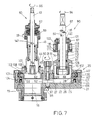
- FIGS. 7 and 8 shows an alternative to the type described in the preceding figures and is shown on a pipe socket 10 before it is coupled.
- the same reference numerals are used to designate corresponding components as in the previous exemplary embodiment according to FIGS. 1 to 6, which is why the previous description applies to this extent. It is sufficient to only deal with the differences.
- the hatching of the components in axial section reflects the choice of material according to the DIN standard in the present invention.
- the cylinder 25 of its upper part 22 is provided at its upper end with an outwardly facing flange 100 which is arranged approximately in the height region of the upper plate 27.
- the cylinder wall 24 of the lower capsule part 21 is widened at its upper front end in order to position a counter flange 102 on the outer surface 103 of the flange 100 by means of bolts 101 or the like, while the inner surface 104 of the flange 100 of the front axial surface 105 of the lower part Cylinder 24 is opposite.
- two sets of balls 40 ' are arranged on the one hand between flange 100 and counter flange 102 and on the other hand between flange 100 and axial surface 105, which ensures smooth rotation 31 of the upper part of the carousel 22 even when the capsule interior 23 has a very high media pressure is exposed.
- a further deviation from the device illustrated in FIGS. 1 and 6 is that, according to FIG. 7, the plunger 51 of the locking mechanism 50 has an axial extension 97 beyond the closing half 52 there, which extends in an axial bore 98 of the capsule lower plate 26 is rotatable and axially displaceable using sealing rings.
- the threaded bores 28 illustrated in FIG. 6 in the upper carousel plate 27 are provided with a larger bore diameter in the exemplary embodiment of FIG. 7, which is why an intermediate ring 106 is first screwed into the threaded bore 28, which in turn has an internal ring thread 107 for receiving the already in connection with 2 has tapping device 60 described.
- the drill housing 44 is supported with its flange 45 on the upper end face of the Intermediate ring 106 from.
- the intermediate ring 106 is provided with radial openings 108 for the engagement of turning tools, such as plug pins, in order to screw the intermediate ring 106 into the threaded bore 28 of the carousel plate 27 in a media-tight manner.
- the further actuation of the tapping device 60 when it is in alignment with the connection point 19 for the pipe socket 10 shown in the previous exemplary embodiment takes place in the manner already explained in connection with FIG. 2.
- the coupling ring 59 of the drilling device 60 can also remain in the uncoupled position shown in FIG. 7 with respect to the clamping screws 67 and, by rotation 99 in the sense of the arrow 99 shown in FIG. 7, an independent drilling feed by unscrewing the outer sleeve 49 relative to the drilling housing 44 cause, while the boring bar 61 undergoes an independent rotation 66.
- the clamping screws 67 remain tightened.
- the independence results from the axially fixed but rotatable connection at the connection point equipped with ball bearings between a clamping bush belonging to the clamping screws 67 on the one hand and the housing outer sleeve 49 on the other hand.
- a sleeve 110 is seated in a media-tight manner and holds an alternative plug-setting device 90 compared to FIG. 4.
- the stuffing box holder 88 has radial spring members 109, which, instead of the magnet described in FIG. 4, mechanically, in the form of a snap closure, produce the desired axial connection for the stopper not shown in FIG. 7, which is non-rotatable but axial insertable and removable with its upper region is inserted into the plug holder 88.
- a plug 91 has one described there External thread 93, which, by rotating movement 94 of the actuating rod 87 also shown in FIG. 7, screws such a plug into the internal thread 15 of the pipe socket 10 shown in FIG. 4.
- a special device is provided in the plug setting device 90 from FIG. 7.
- the bushing 110 of FIG. 7 is also provided with radial openings 108, the function of which has already been described above for the intermediate ring 106.
- the bush cover 111 initially has a media-tight passage 113 for the actuating rod 87 through lip seals 112 or the like, around which a threaded piece 114 is arranged, which extends coaxially to the rod axis 115 indicated by dash-dotted lines in FIG. 7.
- This threaded piece 114 with an external thread is in engagement with the internal thread of a threaded sleeve 116 arranged above it, which carries a circumferential collar 117 at its lower end.
- Bolts 118 which support compression springs 119, are fastened in collar 117, parallel to the axis of the rod 115.
- the thread pitch between the threaded piece 114 and the threaded sleeve 116 is equal to the thread pitch of the aforementioned internal thread 15 in the head 14 of the pipe socket 10 and thus equal to the thread pitch in the external thread 93 of the associated plug shown in FIG. 4.
- the above-mentioned device includes a releasable connection 120 which can be seen in FIG. 7 and which engages on the actuating rod 87.
- This consists here of a clamping bush 121 which, via the clamping screws 67 already described in connection with FIG. 2, optionally creates a connection that is both non-rotatable and axially fixed to the actuating rod 87 of FIG. 7.
- the clamping bush 121 is slotted longitudinally and is attached to the desired one via the clamping screws 67 Position of the actuating rod 87 fixable.
- the clamping screws 67 hold an upper bush 122 equipped with an end radial flange 123, which slidably encloses the circumference of the threaded sleeve 116.
- the upper bushing 122 is always connected in a rotationally fixed and axially fixed manner to the clamping bushing 121. Its radial flange 123 is provided with openings 124, from which the bolts 118 located in the collar 117 of the threaded sleeve 116 protrude.
- the compression springs 119 which are supported at one end on head-like widenings of the bolts 118, are supported at the other end on the upper side of the radial flange 123 and thus endeavor to keep the upper bush 122 axially pressed against the threaded sleeve collar 117. This is important for the assembly process of the plug in the internal thread 115 of the pipe socket 10 from FIG. 4, which has already been mentioned several times.
- connection 120 to the actuating rod 87 is first released in that the clamping action emanating from the clamping screws 67 is ineffective. Then, as has already been described in FIG. 4, the actuating rod 87 is retracted axially in the direction of the arrow 92 there until the stopper, which is located in the stopper holder 88 and is not shown in FIG. 7, with its threaded piece 93 from FIG. 4 on the internal thread 15 of the pipe socket 10 strikes. The connection 120 is then fixed, which is brought about by screwing in the clamping screws 67. Then the clamping bush 121 acts on the actuating rod 87 in a rotationally and axially fixed manner.
- This device can also be used at the same time, in the described retraction 92 of the actuating rod 87, to exert a certain pressure force via the springs 119 on the plug 91 hitting the head 13 of the pipe socket 10, which is then fixed by screwing in the clamping screws 67 Connection 120 effected on the rod. Then, right at the start of the rotation 94, the plug 91 is under a certain axial pressure, which ensures that the threads 93, 15 move securely into one another in the plug region.
- FIG. 8 shows the device already described in FIG. 7, but with different or differently mounted assembly tools, namely a tapping device 60 and a valve setting device 130. It is only necessary to go into the further measures that are not already in connection with the preceding ones Fig. And in particular have been described with Fig. 7.
- the tapping tool 60 with its longitudinal center line 18 is currently in alignment with the socket pipe 19, in which the pipe socket (not shown in more detail) engages in the coupling case.
- these conditions only arise when the actual drilling work has been carried out, which, beforehand, takes place in the following way:
- the clamping screws 67 are tightened, thus establishing an axially fixed and rotationally fixed connection to the boring bar 61 and the cutting tool 63 according to FIG. 2. Also in FIG. 8, similar to FIG. 7, the cutting tool 63 is not shown, which sits in the chuck 62 and acts on the drilling point 16 shown in FIG. 1 during drilling. If the coupling ring 59 is brought into engagement with the clamping screws 67, the drilling feed 65 results from the rotation 66 of the boring bar 61 by screwing the two drill housing parts 44, 49 into one another.
- the coupling ring 59 is out of engagement with the clamping screws 67, one obtains the drilling feed 65 by rotating the coupling ring 59 independently of the boring bar rotation 66, for example if turning pins are inserted into the radial holes provided there.
- This embodiment has the advantage that the drill 60 comes into a lower position with its key attachment 64 because it sits directly on the pipe socket 10. The weight of both the tapping device 60 and the drive means seated at its rod end 64 is then directly absorbed by the pipe socket 10 while protecting the capsule 20. If the line 11 is drilled through, the pressure medium can only enter the interior of the drill housing 44, where it passes through the mentioned sealant shielded from the environment.
- the capsule 20 with its sleeve 126 which can be seen in FIG. 8 but is initially empty, is then placed on the drilling device 60 fixed on the pipe socket 10.
- the sleeve pipe 19 in FIG. 1 has a larger internal width than in FIG. 2, which is why the housing collar 45 fits through.
- the capsule 20 is then attached to the outer circumference of the neck head 13 via the coupling 32 already described in connection with FIG. 1.
- the end of the boring bar 61 is led out in a media-tight manner in the upper region of the bush 126, which has the appropriate structure.
- the bush 126 first comprises a protective cylinder 127 with a threaded piece at the lower end of the cylinder which is screwed directly into the threaded bore 28 of the carousel plate 27. At the upper end of the cylinder there is a top wall 128, which creates a firm connection with the protective cylinder 127 by means of screw sleeves 129.
- the openings of the screw sleeves 129 like the radial openings 108 in FIG. 7, serve to screw the sleeve 126 onto the capsule 20 beforehand.
- the drill rod 61 of the drilling device is pulled axially all the way up into the one shown in FIG.
- the top wall 128 of the sleeve 126 has a passage 113 through which the protruding end of the boring bar 61 is passed in a media-tight manner when the capsule 20 is placed on it.
- the top wall 128 also has a threaded shoulder, onto which a screw cap 139 with a rubber ring 138 is screwed, the meaning of which will be described in more detail.
- This rotary drive consists of grub screws 136, which are seated in an end face 135 of the drill housing 44.
- the chuck 62 which is firmly connected to the boring bar 61, is in turn provided with a radial flange 134 which carries radial cutouts 133. If the boring bar 61 is pulled up completely, as shown in FIG. 2, the threaded pins 136 engage in the radial cutouts 133 and thus produce the aforementioned rotationally fixed connection. As a result, the drilling housing 44 is screwed out of the socket head 13 during the mentioned rotation of the boring bar 61.
- the drill housing 44, 49 is brought into the upper end position by axially pulling up the drill rod 61, where it is arranged above the lower capsule part 21. 8, it is located entirely inside the sleeve 126.
- the pressure medium flowing out of the open pipe socket 10 does get into the sleeve interior 125, but cannot from there escape into the environment due to the already mentioned media-tight passage of the boring bar 61 through lip seals or the like.
- the position of the entire device 60 according to FIG. 8 can now be easily secured by tightening the screw cap 139. Then the rubber ring 138 presses against the circumference of the boring bar 61 and holds it in the raised position in the sleeve 126.
- the capsule 20 can then be rotated undisturbed, for example, to effectively set the valve setting device 130 shown in FIG. 8.
- This is designed analogously to the plug setting device 90 already described in connection with FIG. 7, which is why it is sufficient to only deal with the differences.
- valve insert 140 At the lower end of the actuating rod 87 of FIG. 8 there is a holder 132 for a valve insert 140, as described in more detail in DE-OS 33 34 890, the content of which is made the subject of the present application.
- the valve housing of this insert 140 should be the pipe socket 10. Accordingly, the insert 140 has a fastening sleeve 142 equipped in the lower section with an external thread 141, the external thread 141 to be screwed into the internal thread 15 of the pipe socket 10 already mentioned several times.
- an angular cap zone 143 having a complementary angular peripheral region, such as a hexagon 144 receives on the valve mounting sleeve 142.
- a constriction is provided in the fastening sleeve 142, into which the hook ends of bow-shaped, radial spring members 109 engage, which have already been mentioned in connection with FIG. 7 and in the case of FIG. 8, in an analogous manner, for the Ensure the axial insertion position of the valve insert 140 in the cap 131 of the holder 132.
- the bushing 126 used in the valve setting tool 130 has a bush cover 111 which is modified compared to the cover wall 128 described above and which is provided with the components already described in connection with FIG. 7 for the plug setting tool 90, which is why the associated preceding description applies.
- this sleeve cover 111 is fastened at 130 to the protective cylinder 127 with the screw sleeves 129 already described above in connection with the tapping device 60 from FIG. 8 and equipped with the seals shown in FIG. 8.
- the valve insert 140 is assembled in a manner analogous to the above-described mode of operation of the plug-setting device 90 from FIG. 7, which is why it is sufficient to point out the following:
- the actuating rod 87 is pushed downward by axial downward movement in the sense of the aforementioned arrow 92 until the valve insert 140 held by the spring members 109 touches the internal thread 15 of the pipe socket 10 shown in FIG. 4 with its external thread 141. Then the rotation 94 of the boring bar 87 and its valve insert holder 132 takes place, the connection 120 also being fixed in the case of FIG. 8, according to FIG. 7. Due to the rotational driving 143, 144, the valve insert 140 is then screwed into the pipe socket 10, and because of the axially resilient coupling between the threaded sleeve 116 and the clamping bush 121 already described in connection with FIG. 7, the screwing movements described can be axially adjusted. It is understood that, of course, also in the case of FIG. 8, the threaded piece 114 with its threaded sleeve 116 has the same thread pitch as that which comes into engagement Threads 141, 15 between the valve insert 140 and the pipe socket 10.
- the fully assembled valve insert 140 is then screwed into the head 13 of the pipe socket 10. Then the actuating rod 87 is raised axially, contrary to the arrow 92 in FIG. 8. When a certain limit force is exceeded, the spring members 109 then release the fastening sleeve 142 by springing out of the constriction. The axial cohesion between the valve insert 140 and the holder 132 is thus released. Finally, by further axial movement, the holder cap 131 also releases the hexagon 144 on the valve sleeve 142. The actuating rod 87 can be moved all the way up, so that the empty holder 132 with its cap 131 moves fully into the socket interior 125. Then the capsule 20 of the device according to the invention has fulfilled its task.
- the pipe socket is closed by the valve insert 140.
- the capsule 20 can be removed by loosening the coupling with all tools. For this it is only necessary to screw back the union nut 33 shown in FIG. 1.
- valve insert 140 located in the head 13 of the pipe socket 10 can then be firmly welded to the pipe head 13 in its outer joint area.
- the weld seam thereby closes the ring joint between the fastening sleeve 142 and the pipe head 13.
- the pipe socket 10 of FIG. 1 is then the valve housing.
- the valve slide 146 presses the valve plate 145 against an annular shoulder which is then provided in the interior of the pipe socket 10 and which is located in FIG. 1 below the branch pipe 12 in the pipe socket 10 and consists, for example, of a ring welded there can.
- the hole at the tapping point 16 shown in FIG. 1 for the pipe 11 is closed.
- the valve disk lifts off the annular shoulder and increasingly leaves a passage between the pipeline 11 and the branch pipe 12, as a result of which the medium can then flow.
- the upper housing part 49 of the drilling device 60 can be provided with a small viewing window 147 in the form of a radial bore, through which the exact position of the upper end from the lower housing part 44 can be observed.
- This viewing window 147 is not detrimental to the media tightness, because the boring bar 61 is guided through a lip seal in a media-tight manner in the axial bore of the lower housing part 44.
Landscapes
- Engineering & Computer Science (AREA)
- General Engineering & Computer Science (AREA)
- Mechanical Engineering (AREA)
- Earth Drilling (AREA)
Applications Claiming Priority (2)
| Application Number | Priority Date | Filing Date | Title |
|---|---|---|---|
| DE3742018 | 1987-12-11 | ||
| DE3742018 | 1987-12-11 |
Publications (1)
| Publication Number | Publication Date |
|---|---|
| EP0319882A1 true EP0319882A1 (de) | 1989-06-14 |
Family
ID=6342367
Family Applications (1)
| Application Number | Title | Priority Date | Filing Date |
|---|---|---|---|
| EP88120239A Withdrawn EP0319882A1 (de) | 1987-12-11 | 1988-12-03 | Vorrichtung zur Behandlung, insbesondere zum Anbohren, von unter Mediendruck stehenden Rohrleitungen, wie Gas- oder Wasserleitungen |
Country Status (2)
| Country | Link |
|---|---|
| EP (1) | EP0319882A1 (da) |
| DK (1) | DK686988A (da) |
Cited By (1)
| Publication number | Priority date | Publication date | Assignee | Title |
|---|---|---|---|---|
| KR100748173B1 (ko) | 2006-07-25 | 2007-08-09 | 주식회사 경동도시가스 | 가스배관 연결 방법 및 그에 사용되는 장치 |
Citations (3)
| Publication number | Priority date | Publication date | Assignee | Title |
|---|---|---|---|---|
| FR747136A (fr) * | 1931-09-10 | 1933-06-12 | Appareil permettant de faire des embranchements sur tuyauteries d'eau, de gaz, ou autres fluides, sans diminuer leur pression | |
| US2151594A (en) * | 1936-12-03 | 1939-03-21 | Grantham Andrew | Tapping machine |
| DE2315172A1 (de) * | 1973-03-27 | 1974-10-17 | Baenninger Gmbh | Anbohrvorrichtung zum anbohren von kunststoffrohrleitungen |
-
1988
- 1988-12-03 EP EP88120239A patent/EP0319882A1/de not_active Withdrawn
- 1988-12-09 DK DK686988A patent/DK686988A/da not_active Application Discontinuation
Patent Citations (3)
| Publication number | Priority date | Publication date | Assignee | Title |
|---|---|---|---|---|
| FR747136A (fr) * | 1931-09-10 | 1933-06-12 | Appareil permettant de faire des embranchements sur tuyauteries d'eau, de gaz, ou autres fluides, sans diminuer leur pression | |
| US2151594A (en) * | 1936-12-03 | 1939-03-21 | Grantham Andrew | Tapping machine |
| DE2315172A1 (de) * | 1973-03-27 | 1974-10-17 | Baenninger Gmbh | Anbohrvorrichtung zum anbohren von kunststoffrohrleitungen |
Cited By (1)
| Publication number | Priority date | Publication date | Assignee | Title |
|---|---|---|---|---|
| KR100748173B1 (ko) | 2006-07-25 | 2007-08-09 | 주식회사 경동도시가스 | 가스배관 연결 방법 및 그에 사용되는 장치 |
Also Published As
| Publication number | Publication date |
|---|---|
| DK686988D0 (da) | 1988-12-09 |
| DK686988A (da) | 1989-06-12 |
Similar Documents
| Publication | Publication Date | Title |
|---|---|---|
| DE69611942T2 (de) | Anbohrarmatur | |
| DE102007000882B4 (de) | Verbesserte Anbohr-Abzweiganordnung mit einer Kappenanordnung | |
| DE3124641A1 (de) | Verfahren und vorrichtung zum anzapfen eines hauptrohrs zum anschliessen eines abzweigrohrs | |
| EP0245629B1 (de) | Spanneinrichtung an Drehspindeln von Drehmaschinen für kraftbetätigte Werkstückhalter, insbesondere Spannfutter | |
| DE3725240C2 (da) | ||
| DE1477884C3 (de) | Spannfutter mit mehreren die Spannbacken aufnehmenden Schwenkarmen | |
| DE7011159U (de) | Vorrichtung zum einsetzen von ventilen zwischen die flansche einer flanschenrohrverbindung. | |
| DE4304954C2 (de) | Anbohrschelle mit einer Bohrbüchse | |
| DE1950483A1 (de) | Den Stoepsel festhaltender Rohrlochstempel | |
| EP0736718B1 (de) | Anbohrarmatur für vorzugsweise unter Mediendruck stehende Versorgungsleitungen aus Kunststoff | |
| DE3308876C2 (da) | ||
| EP0319882A1 (de) | Vorrichtung zur Behandlung, insbesondere zum Anbohren, von unter Mediendruck stehenden Rohrleitungen, wie Gas- oder Wasserleitungen | |
| DE4239573A1 (de) | Anbohrarmatur | |
| DE19641803C2 (de) | Anbohrarmatur für eine unter Mediendruck stehende Rohrleitung mit einem absperrbaren Ventil | |
| DE19629459C2 (de) | Anbohrarmatur für Kunststoffrohre | |
| DE3820762A1 (de) | Anbohrvorrichtung fuer rohrleitungen | |
| EP0931970B1 (de) | Anbohrarmatur mit Absperrfunktion für ein unter Mediendruck stehendes Hauptrohr | |
| EP0129717A1 (de) | Vorrichtung zum Drehen und Axialbewegen von Bolzen | |
| DE3815083C2 (da) | ||
| EP0811799A2 (de) | Ventil-Anbohrarmatur für vorzugsweise unter Mediendruck stehende Versorgungsleitungen aus Kunststoff | |
| DE19512591C2 (de) | Anbohrarmatur für insbesondere unter Mediendruck stehende Rohre, wie Gas- oder Wasserrohre | |
| DE4244741C2 (de) | Montagevorrichtung für eine Schutzbuchse zur Vermeidung von Inkrustationen im Bereich einer durch eine Anbohrarmatur hergestellten Bohrung | |
| DE19503602A1 (de) | Anbohrvorrichtung für Rohrleitungen | |
| DE3840864A1 (de) | Vorrichtung zur behandlung, insbesondere abdichtung, von unter mediendruck stehenden rohrleitungen, wie hauseinfuehrungen fuer gas oder wasser | |
| DE4006906A1 (de) | Vorrichtung zum anbringen von bauteilen, insbesondere von messsonden an medienfuehrenden leitungen |
Legal Events
| Date | Code | Title | Description |
|---|---|---|---|
| PUAI | Public reference made under article 153(3) epc to a published international application that has entered the european phase |
Free format text: ORIGINAL CODE: 0009012 |
|
| AK | Designated contracting states |
Kind code of ref document: A1 Designated state(s): AT BE CH DE ES FR GB IT LI LU NL SE |
|
| STAA | Information on the status of an ep patent application or granted ep patent |
Free format text: STATUS: THE APPLICATION HAS BEEN WITHDRAWN |
|
| 18W | Application withdrawn |
Withdrawal date: 19890821 |