EP0319894A2 - Méthode et appareil pour ajuster le jeu entre couteaux dans un dispositif pour couper des bandes - Google Patents
Méthode et appareil pour ajuster le jeu entre couteaux dans un dispositif pour couper des bandes Download PDFInfo
- Publication number
- EP0319894A2 EP0319894A2 EP88120294A EP88120294A EP0319894A2 EP 0319894 A2 EP0319894 A2 EP 0319894A2 EP 88120294 A EP88120294 A EP 88120294A EP 88120294 A EP88120294 A EP 88120294A EP 0319894 A2 EP0319894 A2 EP 0319894A2
- Authority
- EP
- European Patent Office
- Prior art keywords
- knife
- cutting
- clearance
- cutter
- knives
- Prior art date
- Legal status (The legal status is an assumption and is not a legal conclusion. Google has not performed a legal analysis and makes no representation as to the accuracy of the status listed.)
- Withdrawn
Links
Images


Classifications
-
- B—PERFORMING OPERATIONS; TRANSPORTING
- B26—HAND CUTTING TOOLS; CUTTING; SEVERING
- B26D—CUTTING; DETAILS COMMON TO MACHINES FOR PERFORATING, PUNCHING, CUTTING-OUT, STAMPING-OUT OR SEVERING
- B26D7/00—Details of apparatus for cutting, cutting-out, stamping-out, punching, perforating, or severing by means other than cutting
- B26D7/26—Means for mounting or adjusting the cutting member; Means for adjusting the stroke of the cutting member
- B26D7/2628—Means for adjusting the position of the cutting member
-
- B—PERFORMING OPERATIONS; TRANSPORTING
- B26—HAND CUTTING TOOLS; CUTTING; SEVERING
- B26D—CUTTING; DETAILS COMMON TO MACHINES FOR PERFORATING, PUNCHING, CUTTING-OUT, STAMPING-OUT OR SEVERING
- B26D5/00—Arrangements for operating and controlling machines or devices for cutting, cutting-out, stamping-out, punching, perforating, or severing by means other than cutting
-
- Y—GENERAL TAGGING OF NEW TECHNOLOGICAL DEVELOPMENTS; GENERAL TAGGING OF CROSS-SECTIONAL TECHNOLOGIES SPANNING OVER SEVERAL SECTIONS OF THE IPC; TECHNICAL SUBJECTS COVERED BY FORMER USPC CROSS-REFERENCE ART COLLECTIONS [XRACs] AND DIGESTS
- Y10—TECHNICAL SUBJECTS COVERED BY FORMER USPC
- Y10T—TECHNICAL SUBJECTS COVERED BY FORMER US CLASSIFICATION
- Y10T83/00—Cutting
- Y10T83/04—Processes
-
- Y—GENERAL TAGGING OF NEW TECHNOLOGICAL DEVELOPMENTS; GENERAL TAGGING OF CROSS-SECTIONAL TECHNOLOGIES SPANNING OVER SEVERAL SECTIONS OF THE IPC; TECHNICAL SUBJECTS COVERED BY FORMER USPC CROSS-REFERENCE ART COLLECTIONS [XRACs] AND DIGESTS
- Y10—TECHNICAL SUBJECTS COVERED BY FORMER USPC
- Y10T—TECHNICAL SUBJECTS COVERED BY FORMER US CLASSIFICATION
- Y10T83/00—Cutting
- Y10T83/141—With means to monitor and control operation [e.g., self-regulating means]
- Y10T83/148—Including means to correct the sensed operation
-
- Y—GENERAL TAGGING OF NEW TECHNOLOGICAL DEVELOPMENTS; GENERAL TAGGING OF CROSS-SECTIONAL TECHNOLOGIES SPANNING OVER SEVERAL SECTIONS OF THE IPC; TECHNICAL SUBJECTS COVERED BY FORMER USPC CROSS-REFERENCE ART COLLECTIONS [XRACs] AND DIGESTS
- Y10—TECHNICAL SUBJECTS COVERED BY FORMER USPC
- Y10T—TECHNICAL SUBJECTS COVERED BY FORMER US CLASSIFICATION
- Y10T83/00—Cutting
- Y10T83/465—Cutting motion of tool has component in direction of moving work
- Y10T83/4766—Orbital motion of cutting blade
- Y10T83/4795—Rotary tool
- Y10T83/4847—With cooperating stationary tool
-
- Y—GENERAL TAGGING OF NEW TECHNOLOGICAL DEVELOPMENTS; GENERAL TAGGING OF CROSS-SECTIONAL TECHNOLOGIES SPANNING OVER SEVERAL SECTIONS OF THE IPC; TECHNICAL SUBJECTS COVERED BY FORMER USPC CROSS-REFERENCE ART COLLECTIONS [XRACs] AND DIGESTS
- Y10—TECHNICAL SUBJECTS COVERED BY FORMER USPC
- Y10T—TECHNICAL SUBJECTS COVERED BY FORMER US CLASSIFICATION
- Y10T83/00—Cutting
- Y10T83/768—Rotatable disc tool pair or tool and carrier
- Y10T83/7863—Tool pair comprises rotatable tool and nonrotatable tool
Definitions
- the present invention relates to sheet cutters used in pulp and paper industry, and more particularly, it relates to the cutting of web material into sheets and a method for adjusting the clearance between the cutting knives in sheet cutters.
- the invention relates to a method for adjusting the clearance between the cutting knives in sheet cutters, in which the web material is cut by means of a cutter drum rotated by drive means and provided with cutting knives, and a counter knife disposed in a knife support and positioned at knife clearance distance from the moving cutting knives.
- the invention also relates to an apparatus for carrying out the method for adjusting the clearance between the cutting knives in sheet cutters which include a cutter drum rotated by drive means and provided with cutting knives, and a counter knife disposed in a knife support, the web material to be cut being arranged to be fed between the cutting knives and the counter knife so as to cut the web.
- Fig. A1 illustrates this solution.
- Fig. A1 is a schematic side view of the attaching and adjusting system of the counter knife in a sheet cutter, in which the cutter drum with its cutting knife are left out of the drawing.
- counter knife 22 is attached to knife support 23, which in turn has been attached to the frame structure of the sheet cutter not shown in the figure.
- Counter knife 22 is adjustably attached to counter knife support 23 by means of a plurality of adjusting screws 22a in a row across the width of the counter knife. Counter knife 22 is thus adjusted by adjusting screws 22a in the direction of the clearance between the cutting knives.
- the web to be cut moving over counter knife 22 is guided by guiding plate 24 supported by support 25.
- Figure A2 is a schematic side view of a sheet cutter and its adjusting system according to previously known technique.
- the sheet cutter according to fig. A2 comprises a cutter drum 20 provided with cutting knives 21.
- Cutter drum 20 is arranged to rotate in the frame structure of the cutter.
- Counter knife 22 is attached to counter knife support 23 and the web to be cut, which is moving over the counter knife, is arranged to be guided by guiding plate 24, which is supported by support 25.
- the web material to be cut is fed into the cutter by feed rolls 26.
- the system according to fig. A2 comprises thermostat controlled water circulation heating, which maintains cutter drum 20 and counter knife support 23 at a constant temperature.
- Counter knife support 23 is thus provided with piping, in which water heated by a first resistance heater 27 is being circulated by means of a first pump 28.
- cutter drum 20 is provided with piping, in which water heated by a second thermostat-controlled resistance heater 29 is circulated by means of a second pump 30.
- the temperature of the water circulated has been selected to keep the temperature of the structure higher than the temperature of the web to be fed into the cutter. This system has proved quite reliable in practice.
- the system according to fig. A2 does not remove or correct the fact that the clearance between the cutting knives in sheet cutters tends to alter due to normal wear in the knives.
- the object of the present invention is to improve the previously known solutions.
- the method according to the invention is characterized in that the cutting forces acting on the cutting knives of the sheet cutter, or their effect on the structure of the sheet cutter during operation of the sheet cutter are measured, and the readings are used as the command variable for the knife clearance.
- the apparatus according to the invention is in its turn characterized in that the sheet cutter is provided with at least one sensor or corresponding means for measuring the forces acting on the cutting knives of the sheet cutters, or the effect of the cutting forces on the structure of the sheet cutter during its operation, processing and controlling means for the information from the sensor, and a continuous-action device for adjusting the knife clearance, which is arranged to maintain the desired clearance between the cutting knives of the sheet cutter using as command impulses the information from the sensor fed by the processing and control means.
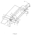
- FIG.1 is a schematic perspective view of a cross section of a sheet cutter where the method and apparatus according to the invention are employed.
- the sheet cutter comprises a cutting drum 1 provided with cutting knives 2.
- Cutting drum 1 is rotatably mounted in bearings on a frame 7 by means of bearing housings 3.
- Cutting drum 1 is rotated by drive means 4, which can, according to FIG. 1, be directly mounted on the shaft of cutting drum 1, or alternatively, suitable power transmission means can be arranged between drive means 4 and the shaft of cutting drum 1.
- FIG.1 also shows a hatched area 10, hereafter called “measure section”, this being the distance between bearing housings 3 of cutting drum 1 and cutter frame 7, and the points where counter knife support 6 and cutter frame 7 are attached to each other.
- FIG .2 is a schematic illustration of the cutting forces prevailing during the cutting process.
- FIG .2 shows schematically a rotatable cutting drum 1 equipped with knives 2 and a counter knife 5 attached to a counter knife support 6.
- Reference F1 and the arrow symbolizing it is a force component resisting the rotation of cutting drum 1, i.e. a force component tangential to the circle described by the rotating knives, in other words the main cutting force.
- Reference F2 and the arrow symbolizing it is a force component attempting to spread apart from each other counter knife 5 and rotating knife 2, i.e. a force component in the direction of the radius of the circle described by rotating knife 2, or in other words, the spreading force.
- the spreading force F2 is thus defined as being right-angled to the main cutting force F1.
- the main cutting force F1 attempts to slow down the rotation speed of cutting drum 1 and the spreading force F2 attempts to widen the gap between counter knife 5 and the rotating knife 2.
- cutting quality is meant a visual estimate of how neat the cut is, and the rate of fiber knots based on the number of knots per a certain unit of pulp. Fiber knots are fibers tightly bonded to each other, which do not become separated in the pulp slushing process preceding paper making, but cause the so called fish-eye phenomenon in the end product. The consequence is bad printability and thus a product of inferior quality.
- the forming of fiber knots is typical of birchwood pulp, which contains hemicellulose. This phenomenon is of little consequence where soft wood pulp is concerned.
- FIG.3 is a schematic and partial perspective view of a sheet cutter, where reference numeral 1 refers to a cutting drum, the periphery of which is schematically shown as dash lines.
- Reference numeral 3 refers to one of the bearing housings by means of which the cutting drum is rotatably mounted on a frame 7 of the sheet cutter.
- Cutting drum 1 is rotated by means of drive means 4.
- Attached to frame 7 is also a counter knife support 6, whereto in turn counter knife 5 is attached.
- reference numeral 10 refers to a certain measure section, by which is meant the distance between cutting drum 1 and counter knife support 6. In the arrangement according to the invention, the knife clearance is set by adjusting the said measure section 10 or the distance between counter knife support 6 and cutting drum 1.
- Measure section 10 may be adjusted by various means, but preferably by altering the temperature of measure section 10, as mechanical adjustment is often too inaccurate.
- the temperature of measure section 10 may be altered by various means and FIGS 4 and 5 show two preferred embodiments.
- reference numeral 10a refers to the measure section.
- piping, a channel system, or the like, 12 is connected to measure section 10a, wherein a heatable medium, such as liquid, preferably water, is circulated.
- Piping 12 is connected to a resistance heater 11, which is suitably controllable, for instance thermostat controlled in such a way that the temperature of the medium can be adjusted as desired.
- the medium is circulated in piping 12 by means of a pump 13.
- measure section 10b is fitted with a temperature controller 14, e.g. electric resistance or the like, by means of which the temperature of measure section 10 can be adjusted.
- Cutting forces F1 and F2 cause vibrations in the sheet cutter frame.
- the vibration level of the frame is proportional to the cutting forces F1 and F2, so that the magnitude of these forces can be directly calculated from the frequency range of the vibrations.
- the basis for the adjustment system according to one embodiment of the invention is the vibration level, according to which the knife clearance is adjusted.
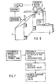
- FIGS 6 and 7. This embodiment of the invention is illustrated in FIGS 6 and 7.
- a sensor 15 is disposed in the counter knife support 6 for measuring the frequency or acceleration.
- the sensor 15 is shown in FIG.6.
- vibration sensor 15 is specifically placed in counter knife support 6, whereby preferably only the essential frequency range of the cutter structure is being measured.
- FIGS 6 and 7 the processes of the measurement of vibrations and adjustment of the knife clearance are schematically shown as block diagrams.
- Sensor 15 measures the vibrations of counter knife support 6, the vibration level being filtered first and analyzed for frequency range, the purpose being that of removing vibrations which do not belong to the structures, i.e. the frequency range is being 'cleansed'.
- the sensor information is then fed into a processor, which calculates the mean value in a certain period of time.
- the calculated mean value of the frequency range will then be compared with the measured mean value of the previous period.
- the information thus processed is then fed into the controlling or adjusting means, which, on the basis of the control impulses received, alters the temperature of measure section 10, 10a, 10b so as to maintain the desired length of the measure section and thus the desired knife clearance.
- the measure section can thus be either heated or cooled.
- An indirect method of measuring cutting forces is, for instance, the measurement of the torque acting on the shaft of drive 4, which can be carried out either directly on the shaft or as measurement of the torque of drive 4.
- Drive means 4 being an electric motor
- the effective cutting force can be measured through the current consumption of drive means 4, as the cutting force is proportional to the torque of the motor and the torque is proportional to the current consumption of the motor.
- Another embodiment where indirect measurement of forces is used is one where vibration sensors are used in defining the vibration level in the structures and through this defining the effective cutting forces.
- command variable for the thermal apparatus 10-14 can also be used for instance measurement information from force sensors placed in the structures, from torque measuring means between drive means 4 and cutting drum 3, or from the system that measures the current consumption of electric motor.
- the processing of the command variable in relation to the periods of time is in these embodiments, however, entirely proportional to the time analysis of the vibration sensor.
- the outstanding advantage of the adjustment system according to the invention lies in the fact that the knife clearance can be continuously adjusted during operation of the machine.
- the temperature of the structure, specifically that of measure section 10, 10a, 10b, is automatically controlled in such a way that the knife clearance is under all running conditions maintained constant irrespective of the temperature of the web to be cut or of mechanical wear in the knives.
- the system adjusts the knife clearance in such a way that the constant set value is determined both according to the minimum of the occuring cutting forces and according to the optimum quality of the cutting result.
Landscapes
- Life Sciences & Earth Sciences (AREA)
- Forests & Forestry (AREA)
- Engineering & Computer Science (AREA)
- Mechanical Engineering (AREA)
- Details Of Cutting Devices (AREA)
- Nonmetal Cutting Devices (AREA)
Applications Claiming Priority (2)
| Application Number | Priority Date | Filing Date | Title |
|---|---|---|---|
| FI875423A FI79256C (fi) | 1987-12-09 | 1987-12-09 | Foerfarande och anordning foer reglering av skaerbettens bettmellanrum i en arkskaermaskin. |
| FI875423 | 1987-12-09 |
Publications (2)
| Publication Number | Publication Date |
|---|---|
| EP0319894A2 true EP0319894A2 (fr) | 1989-06-14 |
| EP0319894A3 EP0319894A3 (fr) | 1990-09-12 |
Family
ID=8525538
Family Applications (1)
| Application Number | Title | Priority Date | Filing Date |
|---|---|---|---|
| EP19880120294 Withdrawn EP0319894A3 (fr) | 1987-12-09 | 1988-12-05 | Méthode et appareil pour ajuster le jeu entre couteaux dans un dispositif pour couper des bandes |
Country Status (4)
| Country | Link |
|---|---|
| US (1) | US4984490A (fr) |
| EP (1) | EP0319894A3 (fr) |
| JP (1) | JPH01301094A (fr) |
| FI (1) | FI79256C (fr) |
Cited By (5)
| Publication number | Priority date | Publication date | Assignee | Title |
|---|---|---|---|---|
| WO1991017027A1 (fr) * | 1990-05-10 | 1991-11-14 | Buck Byron L | Systeme de decoupage a matrices rotatives pour matiere en feuille |
| EP0459224A1 (fr) * | 1990-05-31 | 1991-12-04 | Siemens Aktiengesellschaft | Méthode d'actionnement d'une presse |
| FR2690643A1 (fr) * | 1992-05-02 | 1993-11-05 | Heidelberger Druckmasch Ag | Dispositif d'ajustage d'une lame de coupe pour le sectionnement de bandes continues de matière. |
| WO2000073029A1 (fr) * | 1999-05-28 | 2000-12-07 | Fabio Perini S.P.A. | Dispositif avec systeme thermique pour gerer l'interference entre deux pieces se deplaçant l'une par rapport a l'autre |
| EP3243614A1 (fr) * | 2016-05-09 | 2017-11-15 | Sidel Participations | Unité de coupe pour une machine d'étiquetage |
Families Citing this family (12)
| Publication number | Priority date | Publication date | Assignee | Title |
|---|---|---|---|---|
| US5176784A (en) * | 1989-03-29 | 1993-01-05 | Somar Corporation | Apparatus for bonding continuous thin film to discrete base plates and film cutting apparatus therefor |
| US5482562A (en) * | 1992-04-02 | 1996-01-09 | Abernathy; Frank W. | Method and an apparatus for the removal of fibrous material from a rotating shaft |
| JP3204764B2 (ja) * | 1992-12-28 | 2001-09-04 | 日立金属株式会社 | ロータリシート切断装置およびその製造方法 |
| JP2883862B2 (ja) * | 1996-11-06 | 1999-04-19 | 明産株式会社 | ロータリーカッターのための接圧制御方法および装置 |
| DE10037709A1 (de) * | 2000-08-02 | 2002-02-14 | Gaemmerler Ag | Schneidvorrichtung |
| US6565700B2 (en) * | 2001-04-25 | 2003-05-20 | The Goodyear Tire & Rubber Company | Heated cutting wheel |
| JP3699458B2 (ja) * | 2003-05-08 | 2005-09-28 | 義昭 垣野 | 切削抵抗検出方法及び切削抵抗による加工制御方法並びに制御装置 |
| NL1027733C2 (nl) * | 2004-12-13 | 2006-06-14 | Vmi Epe Holland | Snijinrichting. |
| FR2922453B1 (fr) * | 2007-10-17 | 2011-01-14 | Millipore Corp | Procede de decontamination et systeme le mettant en oeuvre |
| CN104191651A (zh) * | 2014-07-28 | 2014-12-10 | 上海源惠纸制品有限公司 | 一种刀距可调的瓦楞纸箱印刷开槽机 |
| WO2019239283A1 (fr) * | 2018-06-15 | 2019-12-19 | Fabio Perini S.P.A. | Dispositif à lames rotatives, machine comprenant ledit dispositif, et procédé associé |
| TWI780772B (zh) * | 2021-06-16 | 2022-10-11 | 中傳科技股份有限公司 | 刀具與刀把的配對系統與配對方法 |
Family Cites Families (8)
| Publication number | Priority date | Publication date | Assignee | Title |
|---|---|---|---|---|
| US3186275A (en) * | 1963-07-24 | 1965-06-01 | West Virginia Pulp & Paper Co | Thermal expansion means for maintaining and adjusting cutter knife clearance |
| NO139756C (no) * | 1976-12-21 | 1979-05-02 | Norsk Treteknisk Inst | Fremgangsmaate og anordning til aa kontrollere temperaturspenninger i en sagmaskins sagblad |
| DE2743561C3 (de) * | 1977-09-28 | 1980-09-04 | Jagenberg-Werke Ag, 4000 Duesseldorf | Vorrichtung zum Außerbetriebsetzen des Schneidbetriebes an einem Rotationsquerschneider |
| US4380944A (en) * | 1979-09-10 | 1983-04-26 | Gerber Garment Technology, Inc. | Method for cutting sheet material with variable gain closed loop |
| US4355554A (en) * | 1980-10-10 | 1982-10-26 | Philip Morris Incorporated | Web sectioning apparatus including an interference indicator |
| US4478119A (en) * | 1981-05-11 | 1984-10-23 | Bethlehem Steel Corporation | Adaptive control for a dividing shear |
| US4426897A (en) * | 1981-07-13 | 1984-01-24 | Littleton Francis J | Thermal adjustment method and apparatus for rotating machines |
| EP0230429B1 (fr) * | 1985-06-20 | 1989-10-25 | Wolfgang Mayer | Scie a pierre |
-
1987
- 1987-12-09 FI FI875423A patent/FI79256C/fi not_active IP Right Cessation
-
1988
- 1988-12-05 EP EP19880120294 patent/EP0319894A3/fr not_active Withdrawn
- 1988-12-07 US US07/280,897 patent/US4984490A/en not_active Expired - Fee Related
- 1988-12-09 JP JP63311819A patent/JPH01301094A/ja active Pending
Cited By (6)
| Publication number | Priority date | Publication date | Assignee | Title |
|---|---|---|---|---|
| WO1991017027A1 (fr) * | 1990-05-10 | 1991-11-14 | Buck Byron L | Systeme de decoupage a matrices rotatives pour matiere en feuille |
| US5388490A (en) * | 1990-05-10 | 1995-02-14 | Buck; Byron L. | Rotary die cutting system and method for sheet material |
| EP0459224A1 (fr) * | 1990-05-31 | 1991-12-04 | Siemens Aktiengesellschaft | Méthode d'actionnement d'une presse |
| FR2690643A1 (fr) * | 1992-05-02 | 1993-11-05 | Heidelberger Druckmasch Ag | Dispositif d'ajustage d'une lame de coupe pour le sectionnement de bandes continues de matière. |
| WO2000073029A1 (fr) * | 1999-05-28 | 2000-12-07 | Fabio Perini S.P.A. | Dispositif avec systeme thermique pour gerer l'interference entre deux pieces se deplaçant l'une par rapport a l'autre |
| EP3243614A1 (fr) * | 2016-05-09 | 2017-11-15 | Sidel Participations | Unité de coupe pour une machine d'étiquetage |
Also Published As
| Publication number | Publication date |
|---|---|
| US4984490A (en) | 1991-01-15 |
| FI79256B (fi) | 1989-08-31 |
| FI875423A0 (fi) | 1987-12-09 |
| FI79256C (fi) | 1989-12-11 |
| FI875423A7 (fi) | 1989-06-10 |
| EP0319894A3 (fr) | 1990-09-12 |
| JPH01301094A (ja) | 1989-12-05 |
Similar Documents
| Publication | Publication Date | Title |
|---|---|---|
| EP0319894A2 (fr) | Méthode et appareil pour ajuster le jeu entre couteaux dans un dispositif pour couper des bandes | |
| EP0429161B1 (fr) | Procédé et appareil pour contrôler l'entassement de matière à laminer, procédé et appareil pour fabriquer une feuille et procédé et appareil pour mesurer la température d'une feuille | |
| EP0015974B1 (fr) | Procede de commande de la distance de travail entre deux surfaces cylindriques d'une machine de traitement des fibres et appareil pour la mise en oeuvre du procede | |
| US5398381A (en) | Measuring clothing clearances directly at the facing points | |
| US4148439A (en) | Method and device for controlling the energy consumption in a pulp refining system | |
| US8808499B2 (en) | Apparatus for washing and dewatering pulp, a system for controlling such an apparatus, and a method for processing pulp in such an apparatus | |
| US6274002B1 (en) | Papermaking machine with variable dewatering elements including variable pulse turbulation blades adjusted by computer control system in response to sensors of paper sheet characteristics | |
| JP2694133B2 (ja) | 材料シートを処理する方法及び装置 | |
| CA2296118C (fr) | Dispositif de guidage d'une bande de papier sans fin | |
| FI81632C (fi) | Foerfarande och anordning foer kalandering av en bana. | |
| GB2398083A (en) | Controlling the working gap at a carding cylinder | |
| US4527473A (en) | Thermal adjustment apparatus for rotating machines | |
| US6106671A (en) | Intelligent gap control for improved paper machine profile control | |
| US7735200B2 (en) | Apparatus at a spinning preparation machine, especially a flat card, roller card, or the like, having a roller, e.g. a cylinder, which has a cylindrical clothed peripheral surface | |
| US6830659B2 (en) | Apparatus for measuring the wear of a doctor blade and method in measuring the wear of a doctor blade and in controlling a paper machine | |
| CA2415703A1 (fr) | Methode et equipement ayant trait a une machine a papier ou a un appareil de finition de bande de papier | |
| US5771793A (en) | Calender having a control device | |
| CA2021355C (fr) | Methode de controle en ligne de l'orientation des fibres d'une feuille de papier produite par une machine a papier | |
| US4902384A (en) | Wet press with vibration control | |
| US6317931B1 (en) | Distance measuring device in a spinning preparation machine | |
| US11504755B2 (en) | Device and method for transporting strip material, in particular a hot strip | |
| US5266167A (en) | Method of roll cooling in a paper machine | |
| JP3250204B2 (ja) | カードの短周期斑制御装置 | |
| US5379498A (en) | Method and apparatus for controlling shearing of pile fabric | |
| JPS59614B2 (ja) | カリヨリカコウホウホウ |
Legal Events
| Date | Code | Title | Description |
|---|---|---|---|
| PUAI | Public reference made under article 153(3) epc to a published international application that has entered the european phase |
Free format text: ORIGINAL CODE: 0009012 |
|
| AK | Designated contracting states |
Kind code of ref document: A2 Designated state(s): AT BE DE ES FR IT SE |
|
| PUAL | Search report despatched |
Free format text: ORIGINAL CODE: 0009013 |
|
| AK | Designated contracting states |
Kind code of ref document: A3 Designated state(s): AT BE DE ES FR IT SE |
|
| 17P | Request for examination filed |
Effective date: 19901228 |
|
| 17Q | First examination report despatched |
Effective date: 19920914 |
|
| STAA | Information on the status of an ep patent application or granted ep patent |
Free format text: STATUS: THE APPLICATION IS DEEMED TO BE WITHDRAWN |
|
| 18D | Application deemed to be withdrawn |
Effective date: 19930126 |