EP0319904A2 - Ausrichtvorrichtung und -verfahren für graphisches Material - Google Patents
Ausrichtvorrichtung und -verfahren für graphisches Material Download PDFInfo
- Publication number
- EP0319904A2 EP0319904A2 EP88120342A EP88120342A EP0319904A2 EP 0319904 A2 EP0319904 A2 EP 0319904A2 EP 88120342 A EP88120342 A EP 88120342A EP 88120342 A EP88120342 A EP 88120342A EP 0319904 A2 EP0319904 A2 EP 0319904A2
- Authority
- EP
- European Patent Office
- Prior art keywords
- membrane
- platen
- perimeter
- photographic
- air
- Prior art date
- Legal status (The legal status is an assumption and is not a legal conclusion. Google has not performed a legal analysis and makes no representation as to the accuracy of the status listed.)
- Ceased
Links
Images


Classifications
-
- G—PHYSICS
- G03—PHOTOGRAPHY; CINEMATOGRAPHY; ANALOGOUS TECHNIQUES USING WAVES OTHER THAN OPTICAL WAVES; ELECTROGRAPHY; HOLOGRAPHY
- G03B—APPARATUS OR ARRANGEMENTS FOR TAKING PHOTOGRAPHS OR FOR PROJECTING OR VIEWING THEM; APPARATUS OR ARRANGEMENTS EMPLOYING ANALOGOUS TECHNIQUES USING WAVES OTHER THAN OPTICAL WAVES; ACCESSORIES THEREFOR
- G03B27/00—Photographic printing apparatus
- G03B27/02—Exposure apparatus for contact printing
- G03B27/14—Details
- G03B27/18—Maintaining or producing contact pressure between original and light-sensitive material
- G03B27/20—Maintaining or producing contact pressure between original and light-sensitive material by using a vacuum or fluid pressure
Definitions
- This invention pertains to the method and means for firmly supporting photographic materials in accurate registration during contact exposure, and more particularly to a passive hold-down apparatus and method in which the region beneath an impervious membrane is selectively evacuated in a manner that develops a spreading or migrating hold-down force.
- a passive, pressure differential is established about a flexible membrane that covers the photographic sheets and the exposure plate in a manner that assures removal of air pockets from between the photographic sheets as the force attributable to ambient air pressure is progressively applied.
- a migrating or spreading region of applied force progressively squeezes out residual air from between the photographic sheets and inhibits entrapment of air within pockets at random locations.
- the sheets are therefore placed and held in intimate contact with substantially uniform force over the area of the sheets and exposure plate.
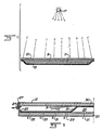
- FIG. 1 there is shown a cross-sectional view of a sheet 9 carrying photographic original images and another sheet 11 of photographically-sensitive materials held together and in place against a glass exposure plate 13 by a flexible blanket 15.
- the sheet materials 9, 11 are held in close surface registration during exposure through the glass plate 13 to a light source 17 positioned above the plate. Structures of this type may also be achieved in inverted orientation when the sheet materials are placed on top of the exposure plate and the flexible blanket 15 weighs down the sheets during exposure to the light source located below the glass plate.
- the flexible blanket 15 and photographic sheet materials positioned between the blanket and exposure plate 13 are forced against the glass exposure plate 13 by positive air pressure acting within the chamber 16 on the side of the blanket 15 remote from the plate 13.
- the positive pressure differential may be established by pressurizing the chamber 16 (within the confining housing 14).
- such techniques commonly isolate pockets of trapped air at locations on the surface of the sheet materials where sufficient air-tight seals 18 formed against the exposure plate (or between sheets) to inhibit evacuation of such volumes of residual air.
- a flexible, gas-impervious blanket or membrane 1 is disposed to separate two air-tight chambers that are formed on opposite sides of the membrane, with the membrane forming a boundary wall of each such chamber, as shown in Figures 3(a) through (e).
- the first or upper chamber 19 another boundary wall is formed by the exposure plate 13 (which may be hinged or otherwise removable 29 [not shown] to facilitate insertion of photographic sheet materials into the chamber).
- a controlling air inlet 21 is positioned in an exterior boundary wall 22 of that chamber to limit the ingress of air at ambient pressure into the second chamber.
- the membrane 15 may be secured and sealed 23 about its periphery to the exterior boundary wall 22 in order to form therewith the air-tight second chamber 20.
- the first chamber 19 is coupled to a vacuum pump (not shown) for evacuating air 24 from between the sheets 9, 11 and from between the sheets and exposure plate 13 in order to assure fixed surface registration between the two sheets during exposure to light through the exposure plate 13.
- the inlet 21 limits the rate of flow of air at ambient pressure into the second chamber 20 that is formed beneath the membrane 15.
- substantially only the local region of the membrane 15 about the inlet 21 is capable of expanding under the pressure differential between ambient pressure admitted into the second chamber 20 through the inlet 21 and the reduced pressure due to evacuation of air 24 evacuated from the first chamber.
- the inlet 21 is positioned within the periphery seal 23 of the membrane, as shown in Figure 3, so that initial expansion of the volume of the second chamber 20 (via flexure of the membrane 15) is limited substantially to the central region 25 about the inlet 21.
- the volume of the second chamber (via flexure of the membrane 15) continues to expand or spread over the surface of the exposure plate 13, as illustrated in Figures 3(c) through (e), until the entire surface area of the sheets 9, 11 are progressively pressed together and against the exposure plate 13.
- the rate of flow of air at ambient pressure through inlet 21 into the second chamber is slower than the rate of flow of air 24 from the first chamber 19 (via a vacuum pump not shown) so that a pressure differential can be maintained across the membrane 15 under conditions which cause progressive, migrating or spreading contact between the membrane 15 and the sheets 9, 11 and the exposure plate 13 from the central location of the inlet 21 toward the periphery of the membrane 15, as illustrated in Figures 3(b) through (e).
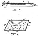
- the first chamber may be evacuated through an outside boundary wall, as illustrated in Figures 4 and 5, for example, near the perimeter of the membrane 15.
- the partial sectional view of the apparatus of the present invention illustrates a plurality of air inlets 29, 31, 33 and 35 at spaced locations intermediate the substantially central inlet 21 and the peripheral seal 23 of the membrane 15 to the lower platen 22.
- Each of these inlets restricts the flow of air at ambient pressure into the forming chamber 25 as the membrane 15 expands the area 30 in which force is applied to urge the sheets 9, 11 into surface contact with the exposure plate 13.
- air at ambient pressure enters beneath the membrane 15 initially only through inlet 21.
- the remaining inlets 29-35 are blocked by the membrane 15 or by active valving techniques, as later described.
- the pressure differential thus established across the membrane 15 progressively squeezes out residual air from between the photographic sheets 9, 11 and exposure plate 13 in a pattern that generally progresses from the central location of the initial air inlet 21 toward the outer limits of the peripheral seal 23 of the membrane 23 to the lower platen.
- the perimeter gasket 27 is provided to facilitate removal of the exposure plate 13 for convenient placement of photographic sheets 9, 11 within the upper chamber, and to form an air-tight seal with the exposure plate 13 when it is in place, as shown.
- air at ambient pressure may be admitted into the first chamber 19, initially from locations about the periphery of the membrane 15 to progressively decrease the area in which surface force of the membrane 15 (and confined sheets 9, 11) against the exposure plate 13 is removed, substantially in the sequence illustrated by Figures 3(e) through (a), in that order.
- the exposure plate 13 may be removed as a boundary wall of the first chamber (for example, by detachment from perimeter gaskets 27, as shown in Figure 4) in order to facilitate removal of the sheets 9, 11 and placement of new photographic materials for contact exposure.
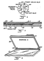
- each of the inlets 21 and 29-35 (designated l, 2, 3, 4 and 5 in Figure 5) are connected to the valve chamber 41, 42 that is coupled to a vacuum supply at conduit 43 and a supply of air at ambient pressure via conduit 44.
- a rotatable plenum 45 is disposed to separate the different air pressures in the valve chamber 41, 42 and to divert either vacuum or air at ambient pressure to the inlets 21 and 29-35 in sequence.
- the plenum 45 may be rotated counter-clockwise to connect vacuum in chamber 41 to the inlets 5, 4, 3, 2, and 1 in that sequence.
- the membrane 15 is thereby drawn away from the exposure plate as air at ambient pressure is admitted to the region between the membrane 15 and exposure plate 13. Once the air pressures on both sides of the exposure plate 13 have equilibrated, the exposure plate 13 may be removed to facilitate removal and re-placement of photographic sheets 9, 11.
- the membrane 15 includes magnetic hold-down means 51-57 spaced at radial or other increments about a central location of an air inlet 21.
- these hold-down means 51-57 may include ceramic magnets embedded in the rubber or plastic membrane 15 (similar to gasket construction for refrigerators) for attractive hold-down on the lower platen formed of steel or other magnetic material.
- flat rings or strips of magnetic material may be positioned within the membrane 15 about the central location of the air inlet 21 for attractive hold-down by permanent magnets positioned in the lower platen to attract the rings or strips of magnetic material.
- the hold-down means between membrane 15 and the lower platen may include a plurality of resilient filaments connected between the membrane 15 and the lower platen to resiliently bias the membrane 15 away from the exposure plate 13 until evacuation of air from between the exposure plate 13 and the membrane 15 establishes a holding force against the exposure plate 13 that migrates from the central region about air inlet 21 toward the perimeter of the membrane 15 near the seal 59.
- the resilient filaments or magnetic hold-down means previously described are particularly advantageous to include with a flexible membrane 15 that is positioned in inverse relationship above the exposure plate 13 that is arranged for exposing photographic sheets therethrough to a light source located below the plate 13.
- the membrane 15 is retained in the removable lid 61 that forms the second chamber on the back side of the membrane 15 (inverse of Figures 2-5) via a plurality of resilient filaments 63, as illustrated in Figures 9(b) through (d) of course, such filaments 63 may be spaced at selected locations and provide graduated resilient force from the least forces near the center to the greatest force near the perimeter of the membrane 15 in order to enhance the migration of the contacting region of the membrane 15 against the sheets 9, 11 and exposure plate 13 as the air therebetween is evacuated.
- the membrane 15 is illustrated as including at least two distinctive regions, each with distinctively different physical characteristics.
- the membrane comprises a dimensionally-stabilizing flexible medium such as DACRON or fiberglass woven cloth 72 that is impregnated with resilient and gas-impervious rubber or other similar polymeric material, with such polymeric material also providing a resilient facing on the membrane 15 for contacting sheets 9, 11.
- the resilient and gas-impervious rubber portion of the membrane 15 extends continuously to the seal 59, but is formed to exhibit highly flexible characteristics in lateral and longitudinal directions. This may be accomplished by omitting the impregnated woven cloth 72 that is present in the central region 71, or by reducing the thickness of the rubber layer that forms the membrane 15 in the perimeter region 73, or by combinations of such features that assure highly flexible, but dimensionally variable continuation of the membrane 15 throughout the perimeter region 73.
- the exterior boundary wall 22 of the removable lid 61 is disposed on the side of the membrane 15 that is opposite the exposure plate 13 to provide the support for the membrane 15 via the resilient filaments 63, or in accordance with any of the embodiments previously described herein.
- the dimensionally-stable central region 71 initially contacts the sheets 9, 11 and presses them against the exposure plate 13, as illustrated in Figure 9(b), as the region between the membrane 15 and the exposure plate 13 is evacuated in a manner as previously described.
- the dimension-stabilizing material 72 may therefore include cloth threads or strips oriented in at least two orthogonal directions, and additionally in the diagonal directions, or may include a thin metal or Mylar layer that is substantially and uniformly dimensionally stable in all directions within the plane of the layer.
- the apparatus and method for supporting photographic sheet materials for contact exposure according to the present invention substantially eliminates air pockets that tend to distort the photographic images on the sheets.
- the apparatus is reduced in weight and strength and cost by efficiently using ambient air pressure to provide the requisite surface-oriented holding forces between the photographic sheets and exposure plate.
Landscapes
- Physics & Mathematics (AREA)
- Fluid Mechanics (AREA)
- General Physics & Mathematics (AREA)
- Exposure And Positioning Against Photoresist Photosensitive Materials (AREA)
- Advancing Webs (AREA)
- Holders For Sensitive Materials And Originals (AREA)
Applications Claiming Priority (2)
| Application Number | Priority Date | Filing Date | Title |
|---|---|---|---|
| US07/131,377 US4812883A (en) | 1987-12-10 | 1987-12-10 | Graphic material registration apparatus and method |
| US131377 | 2002-04-24 |
Publications (2)
| Publication Number | Publication Date |
|---|---|
| EP0319904A2 true EP0319904A2 (de) | 1989-06-14 |
| EP0319904A3 EP0319904A3 (de) | 1989-11-23 |
Family
ID=22449192
Family Applications (1)
| Application Number | Title | Priority Date | Filing Date |
|---|---|---|---|
| EP88120342A Ceased EP0319904A3 (de) | 1987-12-10 | 1988-12-06 | Ausrichtvorrichtung und -verfahren für graphisches Material |
Country Status (4)
| Country | Link |
|---|---|
| US (1) | US4812883A (de) |
| EP (1) | EP0319904A3 (de) |
| JP (1) | JPH01200346A (de) |
| CA (1) | CA1306381C (de) |
Cited By (2)
| Publication number | Priority date | Publication date | Assignee | Title |
|---|---|---|---|---|
| EP0505865A3 (en) * | 1991-03-27 | 1992-11-19 | Siegfried Theimer Grafische Geraete Gmbh | Method of exposing printing plates |
| DE19942213A1 (de) * | 1999-09-03 | 2001-04-12 | Bacher Graphische Geraete Gmbh | Spindelrahmen |
Families Citing this family (5)
| Publication number | Priority date | Publication date | Assignee | Title |
|---|---|---|---|---|
| US4916484A (en) * | 1987-12-10 | 1990-04-10 | Ernest Ohlig | Graphic material registration apparatus and method |
| JPH0447708Y2 (de) * | 1988-10-31 | 1992-11-11 | ||
| SE465593B (sv) * | 1989-02-14 | 1991-09-30 | S T D Engineering Ab | Foerfarande och anordning vid kopiering av ljuskaensliga plaatar |
| US5019866A (en) * | 1989-10-11 | 1991-05-28 | Eastman Kodak Company | Pressurized screen assembly for exposure of a continuous tone image |
| US5298940A (en) * | 1993-01-28 | 1994-03-29 | Ohlig Albert H | Rapid vacuum hold down system and method |
Family Cites Families (22)
| Publication number | Priority date | Publication date | Assignee | Title |
|---|---|---|---|---|
| JPS5127571B2 (de) * | 1972-11-16 | 1976-08-13 | ||
| US3813682A (en) * | 1972-11-20 | 1974-05-28 | Dainippon Screen Mfg | Photomechanical camera |
| DE2356842A1 (de) * | 1973-11-14 | 1975-05-22 | Steininger Hans Peter | Kopiergeraet zur herstellung von reproduktionen im kontaktkopierverfahren |
| GB1511332A (en) * | 1974-04-30 | 1978-05-17 | Hoechst Ag | Printing frame |
| US3955163A (en) * | 1974-06-24 | 1976-05-04 | The Computervision Corporation | Method of positioning a semiconductor wafer for contact printing |
| JPS5229739A (en) * | 1975-09-02 | 1977-03-05 | Dainippon Screen Mfg Co Ltd | Close contact printing device |
| US4211808A (en) * | 1977-11-10 | 1980-07-08 | Roberts & Porter, Inc. | Backing sheet |
| US4240743A (en) * | 1978-05-08 | 1980-12-23 | Teaneck Graphics Corp. | Vacuum frame |
| US4176949A (en) * | 1978-08-03 | 1979-12-04 | Burgess Industries, Inc. | Microfiche exposer |
| US4360266A (en) * | 1979-08-24 | 1982-11-23 | Dai Nippon Insatsu Kabushiki Kaisha | Contact printing method and apparatus |
| US4360259A (en) * | 1981-02-13 | 1982-11-23 | Burgess Dennis A | Diazo developing apparatus |
| DE3122707C2 (de) * | 1981-06-06 | 1983-07-07 | Siegfried 6484 Birstein Theimer | Andrückvorrichtung für die Gummimatte eines Kontaktkopiergeräts |
| US4423851A (en) * | 1981-08-12 | 1984-01-03 | Heitmann Svend A | Rubber cloth for copying machines |
| US4437759A (en) * | 1981-09-17 | 1984-03-20 | Dainippon Screen Seizo Kabushiki Kaisha | Contact printer |
| US4526463A (en) * | 1982-07-30 | 1985-07-02 | CH2 M Hill, Inc. | Apparatus for exposing photosensitive media |
| US4484813A (en) * | 1983-01-24 | 1984-11-27 | Douthitt Corporation | Vacuum printer |
| US4464047A (en) * | 1983-03-16 | 1984-08-07 | Douthitt Corporation | Overhead multiple lamp mount console for a vacuum printer |
| US4536085A (en) * | 1984-01-27 | 1985-08-20 | Teaneck Graphics Corp. | Multiple vacuum frame unit |
| US4551016A (en) * | 1984-09-26 | 1985-11-05 | Douthitt Corporation | Vacuum printer |
| DE3512667C1 (de) * | 1985-04-06 | 1986-06-19 | Siegfried R. 6484 Birstein Theimer | Kopierrahmen |
| US4676633A (en) * | 1986-06-06 | 1987-06-30 | Burgess Industries Inc. | Progressive directional evacuation of vacuum copy frames |
| US4707125A (en) * | 1986-08-29 | 1987-11-17 | Ernest Ohlig | Photographic registration apparatus and method |
-
1987
- 1987-12-10 US US07/131,377 patent/US4812883A/en not_active Expired - Fee Related
-
1988
- 1988-12-06 EP EP88120342A patent/EP0319904A3/de not_active Ceased
- 1988-12-07 JP JP63309709A patent/JPH01200346A/ja active Pending
- 1988-12-09 CA CA000585488A patent/CA1306381C/en not_active Expired - Lifetime
Cited By (2)
| Publication number | Priority date | Publication date | Assignee | Title |
|---|---|---|---|---|
| EP0505865A3 (en) * | 1991-03-27 | 1992-11-19 | Siegfried Theimer Grafische Geraete Gmbh | Method of exposing printing plates |
| DE19942213A1 (de) * | 1999-09-03 | 2001-04-12 | Bacher Graphische Geraete Gmbh | Spindelrahmen |
Also Published As
| Publication number | Publication date |
|---|---|
| CA1306381C (en) | 1992-08-18 |
| US4812883A (en) | 1989-03-14 |
| EP0319904A3 (de) | 1989-11-23 |
| JPH01200346A (ja) | 1989-08-11 |
Similar Documents
| Publication | Publication Date | Title |
|---|---|---|
| US2956769A (en) | Vacuum frame mat | |
| US4360266A (en) | Contact printing method and apparatus | |
| US4812883A (en) | Graphic material registration apparatus and method | |
| JPS6057216B2 (ja) | ジグ | |
| GB2109716A (en) | Vacuum workpiece holder | |
| US3695760A (en) | Photolithographical image processing apparatus | |
| GB1574663A (en) | Sealing systems | |
| US3126192A (en) | Vacuum holder | |
| US4916484A (en) | Graphic material registration apparatus and method | |
| EP0233977A1 (de) | Vakuumkopierrahmen | |
| GB1500749A (en) | Gas bearing | |
| US3420608A (en) | Vacuum frame and improvements for vacuum frames | |
| US4551016A (en) | Vacuum printer | |
| EP0231067B1 (de) | Photographischer Kopierrahmen mit Stiften | |
| JP3370962B2 (ja) | 真空ドラム上に印刷プレートを保持する装置及び方法 | |
| US3512487A (en) | Method and apparatus for holding patterns on a surface | |
| US4935773A (en) | Vacuum blanket | |
| GB2057628A (en) | Magnetic cushioning and pressure applying means | |
| US4475458A (en) | Vacuum frame for offset printing plates | |
| GB8526880D0 (en) | Vacuum contact system | |
| US5300973A (en) | Track image registration system | |
| JPS62147445A (ja) | 真空接触露光装置 | |
| US5298940A (en) | Rapid vacuum hold down system and method | |
| US5642184A (en) | Method and apparatus for vacuum contact printing | |
| JPH0521076Y2 (de) |
Legal Events
| Date | Code | Title | Description |
|---|---|---|---|
| PUAI | Public reference made under article 153(3) epc to a published international application that has entered the european phase |
Free format text: ORIGINAL CODE: 0009012 |
|
| AK | Designated contracting states |
Kind code of ref document: A2 Designated state(s): AT BE CH DE ES FR GB GR IT LI LU NL SE |
|
| PUAL | Search report despatched |
Free format text: ORIGINAL CODE: 0009013 |
|
| AK | Designated contracting states |
Kind code of ref document: A3 Designated state(s): AT BE CH DE ES FR GB GR IT LI LU NL SE |
|
| 17P | Request for examination filed |
Effective date: 19900423 |
|
| 17Q | First examination report despatched |
Effective date: 19920416 |
|
| STAA | Information on the status of an ep patent application or granted ep patent |
Free format text: STATUS: THE APPLICATION HAS BEEN REFUSED |
|
| 18R | Application refused |
Effective date: 19930919 |