EP0319922A2 - Dispositif pour la lecture optique d'un ruban test présentant au moins un champ d'épreuve - Google Patents
Dispositif pour la lecture optique d'un ruban test présentant au moins un champ d'épreuve Download PDFInfo
- Publication number
- EP0319922A2 EP0319922A2 EP88120374A EP88120374A EP0319922A2 EP 0319922 A2 EP0319922 A2 EP 0319922A2 EP 88120374 A EP88120374 A EP 88120374A EP 88120374 A EP88120374 A EP 88120374A EP 0319922 A2 EP0319922 A2 EP 0319922A2
- Authority
- EP
- European Patent Office
- Prior art keywords
- test strip
- test
- support plate
- pressure element
- receiving
- Prior art date
- Legal status (The legal status is an assumption and is not a legal conclusion. Google has not performed a legal analysis and makes no representation as to the accuracy of the status listed.)
- Granted
Links
Images

Classifications
-
- G—PHYSICS
- G01—MEASURING; TESTING
- G01N—INVESTIGATING OR ANALYSING MATERIALS BY DETERMINING THEIR CHEMICAL OR PHYSICAL PROPERTIES
- G01N21/00—Investigating or analysing materials by the use of optical means, i.e. using sub-millimetre waves, infrared, visible or ultraviolet light
- G01N21/84—Systems specially adapted for particular applications
- G01N21/8483—Investigating reagent band
-
- G—PHYSICS
- G01—MEASURING; TESTING
- G01N—INVESTIGATING OR ANALYSING MATERIALS BY DETERMINING THEIR CHEMICAL OR PHYSICAL PROPERTIES
- G01N33/00—Investigating or analysing materials by specific methods not covered by groups G01N1/00 - G01N31/00
- G01N33/48—Biological material, e.g. blood, urine; Haemocytometers
- G01N33/50—Chemical analysis of biological material, e.g. blood, urine; Testing involving biospecific ligand binding methods; Immunological testing
- G01N33/92—Chemical analysis of biological material, e.g. blood, urine; Testing involving biospecific ligand binding methods; Immunological testing involving lipids, e.g. cholesterol, lipoproteins, or their receptors
Definitions
- the invention relates to a device for optically evaluating a test strip having at least one test field, comprising a housing with a receiving slot for the test strip, measuring optics with a transmitter for illuminating the test field and a receiver for receiving the light remitted by the test field, and an electronic evaluation and Display device.
- the device is particularly intended for examining the cholesterol content of blood.
- a reliable measurement using the above-mentioned device presupposes that the measuring device is not contaminated by previous measurements and that the Always take test strips in a defined position relative to the measuring optics.
- the invention has for its object to design a device of the type mentioned so that all components that come into contact with the strip can be easily cleaned and that a precise alignment of the test strip relative to the measuring optics is guaranteed.
- test strip holder which can be releasably inserted into the receiving shaft and has a receiving groove for the test strip, the width of which corresponds to the width of the test strip over at least part of its length, a support plate arranged at a distance from the groove bottom on the test strip holder and having a measuring opening in the receiving groove below the support plate movably mounted pressure element, which is adjustable between a first position in which it is essentially flush with the groove bottom, and a second position in which it presses the test strip onto the support plate, and a pressure device for adjusting the pressure element between his first and second positions.
- the parts of the test strip provided with the liquid to be examined and the reaction substances only come into contact with the test strip holder and the parts arranged on it.
- the test strip holder can be removed as a whole from the device and thus easily cleaned, so that the measurements are not affected by dirt which are due to previous measurements.
- By pressing the test strip onto the support plate a defined position of the test strip relative to the measuring optics is guaranteed at the same time. It is also possible to close the measuring opening in the support plate by pressing the pressure element without a test strip and thus to perform a dark calibration of the device.
- the liquid to be examined can be applied to a recording field of the test strip without the test strip having to change its position again. It is thus possible to carry out a blank calibration, ie a comparison measurement under identical measuring conditions on the test strip without the dropped substance to be examined.
- test strip In order to secure the test strip not only against lateral displacement, but also against displacement in its longitudinal direction, it is expedient if a stop for the test strip and a clamping device for non-positively holding the test strip in place near the inner end of the receiving shaft and within the device inserted state is provided.
- the bottom of the receiving channel expediently rises from the insertion end thereof towards the support plate. If the test strip is only inserted into the receiving channel, but not yet pressed against the support plate, there is the option of ventilating the test field in this position of the test strip. This can still be ensured that in a Ge covering the receiving shaft a cover pin, which is biased towards the groove bottom of the test strip holder and which pushes the test strip against the groove bottom as long as the test strip is not pressed against the support plate by the pressure device, is slidably mounted near the insertion end of the receiving shaft.
- the support plate and the pressure element can be heated by means of a controllable heating device. Since the test field is clamped between the support plate and the pressure element, its temperature is determined by the temperature of these two components, since the test strip has practically no thermal contact with the surroundings in this area.
- the support plate is designed as a crosspiece of a U-shaped support component, the U-legs of which point towards the channel bottom.
- the pressure element also has a U-shaped cross section and is arranged parallel to the support component between its U-legs, the U-legs of the pressure element being at a distance from the U-legs of the support component.
- a U-shaped heating element carrier is provided, on the U-cross bar a heating element is arranged and the U-legs are enclosed between the U-legs of the pressure element and the support component.
- the heating element carrier is fixed to the housing.
- the support component and the pressure element consist of a material that conducts heat well, for example metal, the heating energy of the heating element can be transferred well to these components.
- the test strip holder is preferably made of plastic, since this material can be easily cleaned and has good thermal insulation properties.
- the device shown in FIG. 1 is used, for example, to examine the cholesterol content of blood a reflectance measurement by means of measuring optics provided in the device.
- the device comprises a housing, generally designated 10, on the top of which a display panel 12 and operating elements 14 can be seen.
- the display element 12 and the operating elements 14 are only indicated schematically. You do not have to match the number and arrangement of an actual device. Their arrangement is irrelevant for the explanation of the present invention.
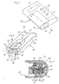
- a receiving shaft 16 can be seen for receiving a test strip holder 18 shown in FIG. 4, into which a test strip 20 can be inserted in a manner to be described (FIGS. 2 and 3).
- a hinged cover 22 in the housing 10 which can be pivoted about an axis 24, so as to release a drip field on the test strip 20 lying in the test strip holder 18, as will be explained in more detail with reference to FIGS. 2 and 3.
- the test strip holder 18 shown in FIG. 4 is a one-piece plastic part 26 with two lateral profile legs 28, which include between them a receiving groove 30 for receiving a test strip 20, the groove bottom 32 according to the illustrations in FIGS. 2 and 3 from the insertion end of the test strip holder 18 to its towards the other longitudinal end pointing towards the inside of the housing.
- the channel bottom 32 thus forms a ramp on which the test strip 20 can be inserted into the device, the width of the section of the receiving channel 30 directly adjacent to the insertion end essentially corresponding to the width of the test strip 20, so that it is guided laterally.
- a U-shaped support component 34 is fixedly arranged between the free ends of the profile rails 28, which bears with its U-legs 36 on the adjacent profile rails 28 and with its U-transverse web 38 forming a support plate the upper edges of the rails 28 are aligned.
- the support member 34 is fixedly connected to the plastic part 26.
- U-shaped pressure element 40 Arranged within the U-shaped support component 34 is a U-shaped pressure element 40, which is directed with its U-legs 42 and its U-transverse web 44 in each case essentially parallel to the corresponding parts of the support component 34, but is at a distance from them .
- the pressure element 40 is pivotally mounted on extensions 46 of the plastic part 26 about an axis 47 shown in FIG. 4, so that it is aligned with the ramp-shaped channel bottom 32 in a first position suitable for receiving a test strip 20 (FIG. 2) and in one of the pressure position of the test strip 20 at the second position corresponding to the support plate 38 lies parallel to the support plate 38 (FIG. 3).
- the pressure element 40 is also preferably made of metal.
- U-legs 48 of a U-shaped heating element carrier 50 engage between the U-legs 36 and 42 of the support component 34 and the pressing element 40, which is arranged below the receiving shaft 16 in the housing 10 and carries a heating element 54 on the outside of its U-crosspiece 52, which is far from the test strip holder 18.
- the heating element carrier transfers heat to the pressure element 40 and the support component 34 by means of heat conduction and heat radiation.
- a two-armed pressure lever 58 is pivotally mounted about an axis 56. It engages with its one lever arm 60 between the extensions 46 under the U-crosspiece 44 of the pressure element 40. Its opposite lever arm is formed by a leaf spring 62 which bears against the circumference of a cam disk 64 which is rotatably mounted in the housing 10 about an axis 66 is.
- the receiving shaft 16 there is an optical system for carrying out the reflectance measurement with a transmitter 70, a deflecting prism 72 and a receiver 74 in an inner housing 58 (FIG. 5).
- the test strip is held in a force-locking manner by a clamping device, which has a notch 80 in one surface delimiting the gap 76 and a locking ball 82 assigned to the notch 80 in the other the gap 76 bordering surface, wherein this detent ball 82 is biased, for example, by a leaf spring 84 in the direction of the notch 80.
- test strip 20 pushed in as far as possible against the stop surface 78 according to FIG. 2 initially lies flat on the channel bottom 32, wherein it is held against the channel bottom 32 by a pressure pin 86 which is resiliently mounted in the housing cover 22.
- the dimensions are chosen so that a test field 88 of the test strip 20 lies exactly between the support plate 38 and the U-cross bar 44 of the pressure element 40 when the test strip 20 is fully inserted.
- the drop field 90 adjoining the test field 88 is exposed.
- the cam disk 64 is now rotated from the position shown in FIG. 2 to the position shown in FIG.
- test image 88 is thus in a well-defined position relative to the measuring optics 70, 72 and 74.
- the beam path from the transmitter 70 runs through the prism 72 and an opening 92 in the housing receiving the optics and through a window 94 in the support plate 38 to test field 38, from where rays are remitted to receiver 74. If no test strip 20 is inserted and the window 94 is closed by pressing the pressure element 40, the device can be darkly calibrated. Furthermore, after the test strip 20 (FIG.
- test strip 20 can also be removed from the device.
- test strip holder 18 which can be pulled out of the device 10 and then easily cleaned. Only the front end of the test strip protruding beyond the test field 88 comes into contact with parts within the device, although contamination in this area cannot influence the measurement results.
- the test strip can easily be brought into a constant, defined position for the measurement, while its temperature can be kept at a predetermined stabilized value. In connection with the convenient possibility of a dark calibration of the measuring device and a clearing, the arrangement according to the invention described above thus enables exact and reproducible measurements to be carried out.
Landscapes
- Life Sciences & Earth Sciences (AREA)
- Health & Medical Sciences (AREA)
- Molecular Biology (AREA)
- Immunology (AREA)
- Chemical & Material Sciences (AREA)
- Engineering & Computer Science (AREA)
- Biomedical Technology (AREA)
- Hematology (AREA)
- General Physics & Mathematics (AREA)
- Biochemistry (AREA)
- Pathology (AREA)
- Urology & Nephrology (AREA)
- General Health & Medical Sciences (AREA)
- Analytical Chemistry (AREA)
- Physics & Mathematics (AREA)
- Endocrinology (AREA)
- Cell Biology (AREA)
- Biotechnology (AREA)
- Microbiology (AREA)
- Biophysics (AREA)
- Food Science & Technology (AREA)
- Medicinal Chemistry (AREA)
- Investigating Or Analysing Materials By Optical Means (AREA)
- Automatic Analysis And Handling Materials Therefor (AREA)
- Testing Of Optical Devices Or Fibers (AREA)
- Testing Or Measuring Of Semiconductors Or The Like (AREA)
- Eye Examination Apparatus (AREA)
- Investigating Or Analysing Materials By The Use Of Chemical Reactions (AREA)
Priority Applications (1)
| Application Number | Priority Date | Filing Date | Title |
|---|---|---|---|
| AT88120374T ATE93626T1 (de) | 1987-12-09 | 1988-12-06 | Vorrichtung zur optischen auswertung eines mindestens ein testfeld aufweisenden teststreifens. |
Applications Claiming Priority (2)
| Application Number | Priority Date | Filing Date | Title |
|---|---|---|---|
| DE8716270U | 1987-12-09 | ||
| DE8716270U DE8716270U1 (de) | 1987-12-09 | 1987-12-09 | Vorrichtung, insbesondere zum Untersuchen des Cholesteringehaltes von Blut |
Publications (3)
| Publication Number | Publication Date |
|---|---|
| EP0319922A2 true EP0319922A2 (fr) | 1989-06-14 |
| EP0319922A3 EP0319922A3 (en) | 1990-05-09 |
| EP0319922B1 EP0319922B1 (fr) | 1993-08-25 |
Family
ID=6814933
Family Applications (1)
| Application Number | Title | Priority Date | Filing Date |
|---|---|---|---|
| EP88120374A Expired - Lifetime EP0319922B1 (fr) | 1987-12-09 | 1988-12-06 | Dispositif pour la lecture optique d'un ruban test présentant au moins un champ d'épreuve |
Country Status (5)
| Country | Link |
|---|---|
| US (1) | US4934817A (fr) |
| EP (1) | EP0319922B1 (fr) |
| AT (1) | ATE93626T1 (fr) |
| DE (2) | DE8716270U1 (fr) |
| ES (1) | ES2045072T3 (fr) |
Cited By (8)
| Publication number | Priority date | Publication date | Assignee | Title |
|---|---|---|---|---|
| DE8907967U1 (de) * | 1989-06-29 | 1989-09-14 | LRE Relais + Elektronik GmbH, 8000 München | Gerät zur remissions-photometrischen Messung von Flüssigkeitsproben |
| DE8907969U1 (de) * | 1989-06-29 | 1989-09-14 | LRE Relais + Elektronik GmbH, 8000 München | Optische Mehrkanal-Meßvorrichtung für die Analyse von Teststreifen |
| EP0618443A1 (fr) * | 1993-03-31 | 1994-10-05 | Boehringer Mannheim Gmbh | Analyseur pour bandes de test |
| DE10338446A1 (de) * | 2003-08-21 | 2005-03-31 | Roche Diagnostics Gmbh | Positioniereinrichtung für ein Testelement |
| DE102004022757B4 (de) * | 2004-05-07 | 2006-11-02 | Lre Technology Partner Gmbh | Streifenauswerfer |
| US7327451B2 (en) | 1998-05-20 | 2008-02-05 | Lre Technology Partner Gmbh | Test strip system |
| DE19861446B4 (de) * | 1998-05-20 | 2012-12-06 | Lre Technology Partner Gmbh | Teststreifensystem |
| WO2013143533A1 (fr) | 2012-03-30 | 2013-10-03 | Seramun Diagnostica Gmbh | Dispositif pour déterminer des échantillons dans un ensemble d'échantillons et support pour ledit dispositif |
Families Citing this family (40)
| Publication number | Priority date | Publication date | Assignee | Title |
|---|---|---|---|---|
| DE8716270U1 (de) * | 1987-12-09 | 1988-02-18 | LRE Relais + Elektronik GmbH, 8000 München | Vorrichtung, insbesondere zum Untersuchen des Cholesteringehaltes von Blut |
| JPH0542351Y2 (fr) * | 1988-03-14 | 1993-10-26 | ||
| DE3844103A1 (de) * | 1988-12-28 | 1990-07-05 | Boehringer Mannheim Gmbh | Testtraeger-analysesystem |
| US5252293A (en) * | 1989-01-17 | 1993-10-12 | Vladimir Drbal | Analytical slide with porous filter membrane |
| AU635314B2 (en) * | 1989-09-08 | 1993-03-18 | Terumo Kabushiki Kaisha | Measuring apparatus |
| US5074662A (en) * | 1990-02-27 | 1991-12-24 | Hoechst Celanese Corporation | Sample holder for spectroscopic studies of optical film |
| US5262650A (en) * | 1990-10-11 | 1993-11-16 | Dentsply Venture Capital Associates, L.P. | Viewer system and method for fluorescence evaluation |
| US5089709A (en) * | 1990-10-11 | 1992-02-18 | Dentsply Venture Capital Associates, L.P. | Test system viewer for fluorescence evaluation |
| US5246858A (en) * | 1991-02-27 | 1993-09-21 | Boehringer Mannheim Corporation | Apparatus and method for analyzing a body fluid |
| US5232668A (en) * | 1991-02-27 | 1993-08-03 | Boehringer Mannheim Corporation | Test strip holding and reading mechanism for a meter |
| JP3118552B2 (ja) * | 1991-02-27 | 2000-12-18 | ロッシュ ダイアグノスティックス コーポレイション | 体液の分析装置及び方法 |
| US5179288A (en) * | 1991-09-30 | 1993-01-12 | Ortho Pharmaceutical Corporation | Apparatus and method for measuring a bodily constituent |
| US5371687A (en) * | 1992-11-20 | 1994-12-06 | Boehringer Mannheim Corporation | Glucose test data acquisition and management system |
| USD367109S (en) | 1995-01-24 | 1996-02-13 | Lifescan, Inc. | Test strip holder |
| US5815259A (en) * | 1996-09-04 | 1998-09-29 | International Business Machines Corporation | Quick change housing |
| US6267722B1 (en) | 1998-02-03 | 2001-07-31 | Adeza Biomedical Corporation | Point of care diagnostic systems |
| US6394952B1 (en) | 1998-02-03 | 2002-05-28 | Adeza Biomedical Corporation | Point of care diagnostic systems |
| USD434153S (en) * | 1998-04-20 | 2000-11-21 | Adeza Biomedical Corporation | Point of care analyte detector system |
| USD432244S (en) * | 1998-04-20 | 2000-10-17 | Adeza Biomedical Corporation | Device for encasing an assay test strip |
| US6652814B1 (en) * | 2000-08-11 | 2003-11-25 | Lifescan, Inc. | Strip holder for use in a test strip meter |
| US20040018114A1 (en) * | 2002-07-26 | 2004-01-29 | Chia-Lin Wang | Test strip holder for a reagent test strip |
| US20040096363A1 (en) * | 2002-11-18 | 2004-05-20 | Larry Porter | Point-of-care assay reader and analyzer |
| US20050124060A1 (en) * | 2003-10-20 | 2005-06-09 | Masaki Yamaguchi | Enzyme activity measuring apparatus, enzyme activity measuring method, sample transcription apparatus and color measuring apparatus |
| US20060133956A1 (en) * | 2004-12-09 | 2006-06-22 | Kenichi Hamanaka | Test strip holder |
| WO2006116705A1 (fr) * | 2005-04-25 | 2006-11-02 | Bayer Healthcare Llc | Mecanisme de liberation de capteur pour un systeme de mesure |
| EP1879018B1 (fr) * | 2006-07-12 | 2015-08-19 | F. Hoffmann-La Roche AG | Système d'analyse et procédé destinés à l'analyse d'un échantillon sur un élément de test analytique |
| WO2010063304A1 (fr) * | 2008-12-05 | 2010-06-10 | Egomedical Swiss Ag | Système de support d’élément de test et dispositif de diagnostic personnel comprenant celui-ci |
| US8661895B2 (en) * | 2009-12-29 | 2014-03-04 | Abbott Diabetes Care Inc. | Carrying cases for medical devices that use analyte test strips and methods of using the same |
| US9933409B2 (en) * | 2011-11-15 | 2018-04-03 | Roche Diabetes Care, Inc. | Strip connector with reliable insertion and ejection |
| WO2013131057A1 (fr) | 2012-03-01 | 2013-09-06 | Quidel Corporation | Système et appareil de diagnostics sur site des soins |
| CN113156107B (zh) | 2012-03-01 | 2024-07-12 | 奎多公司 | 具有计时机制的相互作用的测试装置和设备 |
| KR20130137387A (ko) * | 2012-06-07 | 2013-12-17 | (주)미코바이오메드 | 휴대용 진단 장치 |
| US10101278B2 (en) * | 2013-05-09 | 2018-10-16 | University Of Central Florida Research Foundation, Inc. | Portable spectrometer for the presumptive identification of illicit drugs and substances of abuse |
| US11199498B2 (en) | 2013-05-09 | 2021-12-14 | University Of Central Florida Research Foundation, Inc. | Portable spectrometer for the presumptive identification of substances |
| EP3077798B1 (fr) | 2013-12-06 | 2022-06-22 | Quidel Corporation | Procédé de réduction de la variabilité d'un analyseur au moyen d'une cible de normalisation |
| DK3759469T3 (da) * | 2018-03-02 | 2023-10-09 | Charm Sciences Inc | In-line test med udvikling til diagnostisk analyse |
| US11585804B2 (en) * | 2018-10-19 | 2023-02-21 | Youcount Inc. | Urinalysis device and test strip for home and point of care use |
| CA3049972A1 (fr) | 2019-07-15 | 2021-01-15 | Youcount Inc. | Bandelettes pour l`analyse d`urine en vente libre |
| USD980450S1 (en) * | 2020-07-01 | 2023-03-07 | Erber Ag | Test strip holder |
| CN113406029B (zh) * | 2021-03-25 | 2023-04-07 | 江苏硕世生物科技股份有限公司 | 检测结果读取装置 |
Family Cites Families (9)
| Publication number | Priority date | Publication date | Assignee | Title |
|---|---|---|---|---|
| CA1168064A (fr) * | 1980-03-22 | 1984-05-29 | Klaus Nenninger | Dispositif pour mettre une bande en place pour prendre des mesures optiques en medicine |
| FR2502779A1 (fr) * | 1981-03-26 | 1982-10-01 | Lre Relais & Elektronik Gmbh | Appareil de mesure permettant l'analyse opto-electronique de bandes de papier reactif |
| DE3276136D1 (en) * | 1981-08-28 | 1987-05-27 | Ligg Pty Ltd | Reflectance meter |
| DE3321785A1 (de) * | 1983-06-16 | 1984-12-20 | Boehringer Mannheim Gmbh, 6800 Mannheim | Vorrichtung zum positionieren und festhalten eines teststreifens fuer optisch-medizinische messungen |
| DE3407754A1 (de) * | 1984-03-02 | 1985-09-12 | Boehringer Mannheim Gmbh, 6800 Mannheim | Geraet zur bestimmung des diffusen reflexionsvermoegens einer probenflaeche kleiner abmessungen |
| GB8429211D0 (en) * | 1984-11-19 | 1984-12-27 | Mit Peritronic Ltd | Reflectometer |
| JPS61130859A (ja) * | 1984-11-27 | 1986-06-18 | シンテツクス・ダイアグノステイツク・リミテツド・パ−トナ−シツプ | ポ−タブルアナライザ− |
| EP0253371A1 (fr) * | 1986-07-15 | 1988-01-20 | Omron Tateisi Electronics Co. | Dispositif pour mesurer une substance chimique avec un couvercle facile à manipuler et une seule possibilité de sélection de la fonction |
| DE8716270U1 (de) * | 1987-12-09 | 1988-02-18 | LRE Relais + Elektronik GmbH, 8000 München | Vorrichtung, insbesondere zum Untersuchen des Cholesteringehaltes von Blut |
-
1987
- 1987-12-09 DE DE8716270U patent/DE8716270U1/de not_active Expired
-
1988
- 1988-12-06 EP EP88120374A patent/EP0319922B1/fr not_active Expired - Lifetime
- 1988-12-06 DE DE88120374T patent/DE3883500D1/de not_active Expired - Fee Related
- 1988-12-06 US US07/280,696 patent/US4934817A/en not_active Expired - Fee Related
- 1988-12-06 AT AT88120374T patent/ATE93626T1/de not_active IP Right Cessation
- 1988-12-06 ES ES88120374T patent/ES2045072T3/es not_active Expired - Lifetime
Cited By (12)
| Publication number | Priority date | Publication date | Assignee | Title |
|---|---|---|---|---|
| DE8907967U1 (de) * | 1989-06-29 | 1989-09-14 | LRE Relais + Elektronik GmbH, 8000 München | Gerät zur remissions-photometrischen Messung von Flüssigkeitsproben |
| DE8907969U1 (de) * | 1989-06-29 | 1989-09-14 | LRE Relais + Elektronik GmbH, 8000 München | Optische Mehrkanal-Meßvorrichtung für die Analyse von Teststreifen |
| EP0618443A1 (fr) * | 1993-03-31 | 1994-10-05 | Boehringer Mannheim Gmbh | Analyseur pour bandes de test |
| US5424035A (en) * | 1993-03-31 | 1995-06-13 | Boehringer Mannheim Gmbh | Test strip analysis system |
| EP0816831A3 (fr) * | 1993-03-31 | 1998-01-28 | Boehringer Mannheim Gmbh | Dispositif pour l'évaluation de bandes de test |
| US7327451B2 (en) | 1998-05-20 | 2008-02-05 | Lre Technology Partner Gmbh | Test strip system |
| DE19822770B4 (de) * | 1998-05-20 | 2012-04-12 | Lre Technology Partner Gmbh | Teststreifensystem |
| DE19861446B4 (de) * | 1998-05-20 | 2012-12-06 | Lre Technology Partner Gmbh | Teststreifensystem |
| DE10338446A1 (de) * | 2003-08-21 | 2005-03-31 | Roche Diagnostics Gmbh | Positioniereinrichtung für ein Testelement |
| US7501097B2 (en) | 2003-08-21 | 2009-03-10 | Roche Diagnostics Operations, Inc. | Positioning device for a test element |
| DE102004022757B4 (de) * | 2004-05-07 | 2006-11-02 | Lre Technology Partner Gmbh | Streifenauswerfer |
| WO2013143533A1 (fr) | 2012-03-30 | 2013-10-03 | Seramun Diagnostica Gmbh | Dispositif pour déterminer des échantillons dans un ensemble d'échantillons et support pour ledit dispositif |
Also Published As
| Publication number | Publication date |
|---|---|
| DE8716270U1 (de) | 1988-02-18 |
| US4934817A (en) | 1990-06-19 |
| ES2045072T3 (es) | 1994-01-16 |
| DE3883500D1 (de) | 1993-09-30 |
| EP0319922A3 (en) | 1990-05-09 |
| EP0319922B1 (fr) | 1993-08-25 |
| ATE93626T1 (de) | 1993-09-15 |
Similar Documents
| Publication | Publication Date | Title |
|---|---|---|
| EP0319922B1 (fr) | Dispositif pour la lecture optique d'un ruban test présentant au moins un champ d'épreuve | |
| EP0129220B1 (fr) | Dispositif pour l'évaluation d'un ruban de test à réactif pour la détermination analytique de constituants d'un liquide corporel | |
| EP0431455B1 (fr) | Dispositif d'évaluation de bandes à essais multiples | |
| DE3587817T2 (de) | Vorrichtung zum Bewegen eines Teils entlang einer geschlossenen Kurve. | |
| DE19822770B4 (de) | Teststreifensystem | |
| DE69025110T2 (de) | Testgerät | |
| DE69221306T2 (de) | Methode zur photometrischen (in vitro) bestimmung des gehaltes eines analyts in einer probe | |
| DE4310583A1 (de) | Teststreifenanalysesystem | |
| DE8513365U1 (de) | Blutuntersuchungsvorrichtung mit einer Nadel zum Stechen zur Gewinnung von Blut | |
| DE4425439A1 (de) | Teststreifenauswertegerät mit einer Transporteinheit für Teststreifen | |
| EP0037484B1 (fr) | Dispositif pour positionner et fixer un ruban de test pour mesurages optiques médicaux | |
| DE102004022757B4 (de) | Streifenauswerfer | |
| EP0376111B1 (fr) | Analyseur pour bandes de test | |
| DE2916952C2 (de) | Probenförderer | |
| EP0935773B1 (fr) | Dispositif de couverture des echantillons histologiques et biologiques | |
| EP1929937A1 (fr) | Dispositif et méthode pour analyser des liquides organiques | |
| DE19516981C2 (de) | Teststreifen-Zuführgerät | |
| DE2203603A1 (de) | Detektorvorrichtung für physikalische und/oder chemische Eigenschaften auf einer zu untersuchenden Oberfläche | |
| EP0405513A2 (fr) | Dispositif pour l'analyse photométrique par rémission d'échantillons liquides | |
| DE3011223C2 (de) | Vorrichtung zum Positionieren und Festhalten eines Teststreifens für optischmedizinische Messungen | |
| DE4035052C2 (de) | Testträgeranalysegerät | |
| EP2427101A1 (fr) | Échantillon pour appareil testeur et système de test | |
| DE4113330A1 (de) | Vorrichtung zur photometrischen bestimmung des gerinnungsverhaltens von blut, blutplasma oder dergleichen | |
| DE19861446B4 (de) | Teststreifensystem | |
| WO2012136352A1 (fr) | Système d'analyse avec dispositif de mesure et élément d'essai |
Legal Events
| Date | Code | Title | Description |
|---|---|---|---|
| PUAI | Public reference made under article 153(3) epc to a published international application that has entered the european phase |
Free format text: ORIGINAL CODE: 0009012 |
|
| AK | Designated contracting states |
Kind code of ref document: A2 Designated state(s): AT BE CH DE ES FR GB GR IT LI LU NL SE |
|
| PUAL | Search report despatched |
Free format text: ORIGINAL CODE: 0009013 |
|
| AK | Designated contracting states |
Kind code of ref document: A3 Designated state(s): AT BE CH DE ES FR GB GR IT LI LU NL SE |
|
| 17P | Request for examination filed |
Effective date: 19901108 |
|
| 17Q | First examination report despatched |
Effective date: 19920409 |
|
| GRAA | (expected) grant |
Free format text: ORIGINAL CODE: 0009210 |
|
| AK | Designated contracting states |
Kind code of ref document: B1 Designated state(s): AT BE CH DE ES FR GB GR IT LI LU NL SE |
|
| PG25 | Lapsed in a contracting state [announced via postgrant information from national office to epo] |
Ref country code: GR Free format text: LAPSE BECAUSE OF FAILURE TO SUBMIT A TRANSLATION OF THE DESCRIPTION OR TO PAY THE FEE WITHIN THE PRESCRIBED TIME-LIMIT Effective date: 19930825 |
|
| REF | Corresponds to: |
Ref document number: 93626 Country of ref document: AT Date of ref document: 19930915 Kind code of ref document: T |
|
| REF | Corresponds to: |
Ref document number: 3883500 Country of ref document: DE Date of ref document: 19930930 |
|
| GBT | Gb: translation of ep patent filed (gb section 77(6)(a)/1977) |
Effective date: 19931001 |
|
| ITF | It: translation for a ep patent filed | ||
| ET | Fr: translation filed | ||
| PG25 | Lapsed in a contracting state [announced via postgrant information from national office to epo] |
Ref country code: GB Effective date: 19931206 Ref country code: AT Effective date: 19931206 |
|
| PG25 | Lapsed in a contracting state [announced via postgrant information from national office to epo] |
Ref country code: SE Effective date: 19931207 |
|
| PG25 | Lapsed in a contracting state [announced via postgrant information from national office to epo] |
Ref country code: LU Free format text: LAPSE BECAUSE OF NON-PAYMENT OF DUE FEES Effective date: 19931231 Ref country code: LI Effective date: 19931231 Ref country code: CH Effective date: 19931231 Ref country code: BE Effective date: 19931231 |
|
| REG | Reference to a national code |
Ref country code: ES Ref legal event code: FG2A Ref document number: 2045072 Country of ref document: ES Kind code of ref document: T3 |
|
| PLBE | No opposition filed within time limit |
Free format text: ORIGINAL CODE: 0009261 |
|
| STAA | Information on the status of an ep patent application or granted ep patent |
Free format text: STATUS: NO OPPOSITION FILED WITHIN TIME LIMIT |
|
| BERE | Be: lapsed |
Owner name: LRE RELAIS + ELEKTRONIK G.M.B.H. Effective date: 19931231 |
|
| PG25 | Lapsed in a contracting state [announced via postgrant information from national office to epo] |
Ref country code: NL Effective date: 19940701 |
|
| GBPC | Gb: european patent ceased through non-payment of renewal fee |
Effective date: 19931206 |
|
| NLV4 | Nl: lapsed or anulled due to non-payment of the annual fee | ||
| 26N | No opposition filed | ||
| PG25 | Lapsed in a contracting state [announced via postgrant information from national office to epo] |
Ref country code: FR Effective date: 19940831 |
|
| REG | Reference to a national code |
Ref country code: CH Ref legal event code: PL |
|
| REG | Reference to a national code |
Ref country code: FR Ref legal event code: ST |
|
| PG25 | Lapsed in a contracting state [announced via postgrant information from national office to epo] |
Ref country code: ES Free format text: LAPSE BECAUSE OF NON-PAYMENT OF DUE FEES Effective date: 19941207 |
|
| EUG | Se: european patent has lapsed |
Ref document number: 88120374.9 Effective date: 19940710 |
|
| PGFP | Annual fee paid to national office [announced via postgrant information from national office to epo] |
Ref country code: DE Payment date: 19990129 Year of fee payment: 11 |
|
| PG25 | Lapsed in a contracting state [announced via postgrant information from national office to epo] |
Ref country code: DE Free format text: LAPSE BECAUSE OF NON-PAYMENT OF DUE FEES Effective date: 20001003 |
|
| REG | Reference to a national code |
Ref country code: ES Ref legal event code: FD2A Effective date: 19950112 |
|
| PG25 | Lapsed in a contracting state [announced via postgrant information from national office to epo] |
Ref country code: IT Free format text: LAPSE BECAUSE OF NON-PAYMENT OF DUE FEES Effective date: 20051206 |