EP0319968A2 - Schuh und Innensohle mit einseitig gerichteter Belüftung - Google Patents
Schuh und Innensohle mit einseitig gerichteter Belüftung Download PDFInfo
- Publication number
- EP0319968A2 EP0319968A2 EP88120486A EP88120486A EP0319968A2 EP 0319968 A2 EP0319968 A2 EP 0319968A2 EP 88120486 A EP88120486 A EP 88120486A EP 88120486 A EP88120486 A EP 88120486A EP 0319968 A2 EP0319968 A2 EP 0319968A2
- Authority
- EP
- European Patent Office
- Prior art keywords
- insole
- ventilating
- shoe
- cavity
- upper portion
- Prior art date
- Legal status (The legal status is an assumption and is not a legal conclusion. Google has not performed a legal analysis and makes no representation as to the accuracy of the status listed.)
- Granted
Links
Images

Classifications
-
- A—HUMAN NECESSITIES
- A43—FOOTWEAR
- A43B—CHARACTERISTIC FEATURES OF FOOTWEAR; PARTS OF FOOTWEAR
- A43B17/00—Insoles for insertion, e.g. footbeds or inlays, for attachment to the shoe after the upper has been joined
- A43B17/08—Insoles for insertion, e.g. footbeds or inlays, for attachment to the shoe after the upper has been joined ventilated
-
- A—HUMAN NECESSITIES
- A43—FOOTWEAR
- A43B—CHARACTERISTIC FEATURES OF FOOTWEAR; PARTS OF FOOTWEAR
- A43B7/00—Footwear with health or hygienic arrangements
- A43B7/06—Footwear with health or hygienic arrangements ventilated
- A43B7/08—Footwear with health or hygienic arrangements ventilated with air-holes, with or without closures
- A43B7/081—Footwear with health or hygienic arrangements ventilated with air-holes, with or without closures the air being forced from outside
Definitions
- This invention relates to a kind of shoe, in particular, to a kind of unidirectional airflow ventilating shoe and unidirectional airflow ventilating insole for shoes.
- the existing air-blow shoes focus on either improving the air permeability or accelerating air permeability by increasing the circulation of air within the shoes. As a result, replacement of fresh air is not possible until the gas in the shoes is discharged and therefore the rate of air permeability is very low.
- Other kinds of shoes with air-pump such as DE 3206631, JP 57-134102, GB 2098851, are better ventilated than the air-blow shoe mentioned above.
- the production process thereof is more complicated due to the adoption of a pump and check valve, and since extra materials are required, the production cost and market price are increased.
- the technique for producing the air-pump shoes is not applicable to casual and sports shoes because the adoption of the pump and valve will make the wearer uncomfortable.
- Only one type of such air-pump shoes is manufactured in Taiwan.
- metallic spring and ebonite are used for adopting the pump body and valve thereof, only shoes with hard soles of complicated structure and high cost can be manufactured.
- the object of the present invention is to provide a kind of unidirectional airflow ventilating shoe and unidirectional airflow ventilating insole for shoes, wherein fresh air outside the shoes is forced unidirectionally into the front part of the feet so as to attain higher rate of ventilation.
- the sole and the structure of the upper part of the shoes are concerned, there are no differences between the ventilating shoes of the present invention and ordinary shoes.
- a unidirectional airflow ventilating layer on the sole inside the shoe.
- the heel portion of the layer is provided with a compressible cavity at the bottom surface of the layer.
- the back upper portion of the layer is provided with an elastic closable air inlet and the front portion with an elastic main airflow passage leading to the front part of the layer.
- the fore end of the main airflow passage is splitted up into several branches. The fore end of each branch is provided with an air outlet leading to the upper surface of the layer.
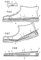
- the unidirectional airflow ventilating layer (1) of a unidirectional airflow ventilating shoe is a sole-shaped elastic material consisting of a thick heel portion and thin front portion, the bottom surface of the elastic materiai being pressed closely to the sole (9) of the shoe.
- a cavity (2) is provided in the heel portion.
- the cross-section of the cavity is arch-shaped, with the peak point of the arch being about 3/4 of thickness of the heel portion and the maximum section area of the arch about 4/5 of the section area of the heel portion, thus guaranteeing a certain capacity and maintaining a considerable degree of elasticity.
- An air inlet (3) is opened up backwardly at the back upper portion of the cavity (2). As illustrated in Fig. 1, air inlet (3) at rear end of the heel is connected to the heel portion inside the shoe.
- the cross-section of air inlet (3) in Fig. 3 is in the shape of a sharp leaf so that it can be completely closed under pressure.
- a main airflow passage (4) is opened up from the front of the cavity (2) to the fore sole (Fig. 2).
- the crosssection of main airflow passage (4) is arch-shaped and the ratio of the height and width is 1:3. The passage is completely closed when bent.
- the main airflow passage (4) is divided into branches (5) at the front end thereof, preferably 2-4 branches.
- the crosssection of branches (5) are preferably in the shape of semi-circles.
- a cyiindrical air outiet (6) is opened up at the front end of each branch (5) and directed at the root of the toes in the shoe (Fig. 3).
- the entire layer (1) can be stuck onto the sole of the shoe.
- Air inlet (3) being located at the part which first touches the ground, will be closed under heavy pressure of the wearer as illustrated in Fig. 5. It can be seen from Fig. 6 that with the centre of gravity being shifted forward, the point of the shoe which touches the ground will also be moved forward. In the meantime, cavity (2) is compressed from the back to the front and the air in the cavity is flowing out through main airflow passage (4), branches (5) and air outlet (6) to the front part of the shoe, and then flowing out through the eyelet, the gaps between the tongue and the edge of the shoe's upper portion.
- this invention also provides a unidirectional airfiow ventilationg insole comprising upper insole (7) and lower insoie (8), as shown in Fig. 8.
- the structure of the upper insole (7) is the same as that of ventilating layer (1) of said unidirectional airflow ventilating shoes.
- Cavity (2), air inlet (3), main airflow passage (4), airflow branches (5) and air outlet (6) are provided in a piece of elastic material.
- Lower insole (8) can either form an entirety with upper insole (7), or be an elastic substrate in the form of a sole closely sealed to the bottom surface of the upper insole.
- a pair of unidirectional airflow ventilating shoes can be made without increasing material cost by replacing the middle soles of such soft-sole shoes as ordinary walking shoes and sport shoes with the unidirectional airflow ventilating insole.
- an air channel provided at the upper portion of each boot and connected with the air inlet of the ventilating insole is enough to change an ordinary boot to a unidirectional airflow ventilating boot.
- Using the ventilating insole in any kind of shoes can attain the same result as unidirectionai airflow ventilating shoes.
- the present invention has several distinctive advantages. For example high rate of ventilating can be accomplished by fresh air outside shoes unidirectionally flowing into the front part, which is the dampest and hottest part inside the shoe, so that the wearer can feel wind blowing towards his feet. This feature also helps prevent stink and disease of feet. Besides, since the materiai used is cheap and the structure is simple, the manufacturing process is convenient and the production cost is low. As no pump body or valve is required, such kind of shoes are comfortable to wear and the insole is suitable to be used with shoes of all classes, regardless of the materials used for the vamp and sole, the thickness of the heel and the heigth of the upper part of the shoes.
- a further merit of the invention is that people suffering from foot disease may spray medical lotion frequently into the unidirectional airflow ventilating layer of the shoe or the cavity and airflow passage of the ventilating insole. As a result, the medical lotion would be blown to the fore part of the feet while the wearer walks. Furthermore, perfume may also be sprayed into the cavity and passage so as to prevent the feet from stinking.
- the first embodiment is a unidirectional airflow ventilating shoe.
- a 30 mm thick PVC (polyvinyl ehloride) or PU (polyurethane) piece is cut into the shape of a sole with the front part cut to 8 mm thick and the longitudinal section being in the form of a right-angled trapezium.
- An arched cavity is excavated at the heel part with the thickest part being 22 mm.
- the external edge of the cavity has 8 mm wide allowances and the capacity of the cavity is approximately 6000 mm3.
- An arched-shaped main airflow passage excavated at the front of the cavity is 3 mm tall and 12 mm wide and is divided into at least two branches as it reaches the front sole; each of said branches is 3 mm tall and 6 mm wide.
- Cylindrical air outlets which have diameters of 6 mm are vertically excavated at the front end of each branch, penetrating the piece.
- Air inlet with tapered leaf-shaped cross-section which are 18 mm wide and 5 mm tall is excavated at the rear upper part of the cavity. The air inlet penetrate backwards the piece. Taking out the middle sole and inner lining cloths of a readymade sports shoe with low upper, applying adhesives all over the sole of the shoe and sticking the excavated surface of the above manufactured piece on the sole, then a unidirectional airflow ventilating shoe will be formed. An experiment shows that about 5000 mm3 fresh air is blown out of the outlets with each step the wearer takes.
- the second embodiment is a unidirectional airflow ventilating insole for shoes.
- a 20 mm thick synthetic rubber piece is used as an upper insole.
- the same processing technique used in the first embodiment is employed. Since the elasticity of rubber is stronger, the thickness of the synthetic rubber can be thinner.
- the front part is cut to 6 mm thick and the capacity of the cavity is about 4000 mm3.
- the arch-shaped main airflow passage is 2 mm tall and 12 mm wide; each of the branches is 2 mm tall and 6 mm wide.
- the sharp leaf-shaped air inlet is 18 mm wide and 3.5 mm tall.
- the air outlets are cylindrical which have diameters of 6 mm.
- a unidirectional airflow ventilating insole is formed.
- the ventilating insole can be used in any kind of shoes and about 3000 mm3 fresh air is blown out of the air outlets with each step while walking.
Landscapes
- Health & Medical Sciences (AREA)
- Epidemiology (AREA)
- General Health & Medical Sciences (AREA)
- Public Health (AREA)
- Footwear And Its Accessory, Manufacturing Method And Apparatuses (AREA)
Applications Claiming Priority (2)
| Application Number | Priority Date | Filing Date | Title |
|---|---|---|---|
| CN 87107387 CN1011285B (zh) | 1987-12-07 | 1987-12-07 | 单向吹气鞋及单向吹气垫 |
| CN87107387 | 1987-12-07 |
Publications (3)
| Publication Number | Publication Date |
|---|---|
| EP0319968A2 true EP0319968A2 (de) | 1989-06-14 |
| EP0319968A3 EP0319968A3 (en) | 1990-03-07 |
| EP0319968B1 EP0319968B1 (de) | 1994-05-18 |
Family
ID=4816063
Family Applications (1)
| Application Number | Title | Priority Date | Filing Date |
|---|---|---|---|
| EP19880120486 Expired - Lifetime EP0319968B1 (de) | 1987-12-07 | 1988-12-07 | Schuh und Innensohle mit einseitig gerichteter Belüftung |
Country Status (4)
| Country | Link |
|---|---|
| EP (1) | EP0319968B1 (de) |
| JP (1) | JPH01262801A (de) |
| CN (1) | CN1011285B (de) |
| DE (1) | DE3889640T2 (de) |
Cited By (7)
| Publication number | Priority date | Publication date | Assignee | Title |
|---|---|---|---|---|
| US4993173A (en) * | 1989-08-29 | 1991-02-19 | Gardiner James T | Shoe sole structure |
| WO1992017081A1 (en) * | 1991-04-02 | 1992-10-15 | Nordica S.P.A. | Ventilated footgear |
| EP0714611A1 (de) | 1994-12-02 | 1996-06-05 | S.A.R.L. Technisynthese | Lüftungsvorrichtung für Schuhe und Verfahren zu deren Herstellung |
| EP0741978A1 (de) * | 1995-05-09 | 1996-11-13 | Antonio Bottecchia | Schuhwerk mit Lüftung |
| WO1998020764A1 (fr) | 1996-11-08 | 1998-05-22 | Jallatte | Article chaussant a circulation d'air et son procede de fabrication |
| WO2003045178A1 (es) * | 2001-11-12 | 2003-06-05 | Angelli S.L. | Valvula de aireacion para calzado |
| EP2007238A4 (de) * | 2006-04-14 | 2011-12-28 | Ka Shek Neville Lee | Fussbekleidungsartikel |
Families Citing this family (8)
| Publication number | Priority date | Publication date | Assignee | Title |
|---|---|---|---|---|
| JP2706909B2 (ja) * | 1995-04-10 | 1998-01-28 | 辰彦 末永 | 靴の中敷および靴 |
| CN2420880Y (zh) * | 2000-01-19 | 2001-02-28 | 河元哲 | 凸底减震排湿鞋 |
| KR101350116B1 (ko) * | 2013-08-06 | 2014-01-08 | 주영대 | 의류 신발용 충격 흡수 구조물 |
| EP3318147B1 (de) * | 2016-11-04 | 2019-08-14 | ATMOS airwalk ag | Schuh mit einer sohlenkonstruktion und einer luftpumpvorrichtung zum einblasen von luft in einen schuhinnenraum |
| CN106937771A (zh) * | 2017-03-10 | 2017-07-11 | 福建起步儿童用品有限公司 | 一种换气呼吸鞋底及其鞋 |
| CN112790469A (zh) * | 2021-02-07 | 2021-05-14 | 鲸动科技(莆田)有限公司 | 一种透气鞋底及鞋内进气方法 |
| CN116326884A (zh) * | 2023-03-25 | 2023-06-27 | 安福康路运动科技有限公司 | 一种防滑耐磨损运动鞋底 |
| CN117694647B (zh) * | 2024-02-01 | 2024-04-19 | 晋江市鑫铭鞋材科技有限公司 | 一种油地面高摩擦止滑橡胶鞋底及其生产工艺 |
Family Cites Families (4)
| Publication number | Priority date | Publication date | Assignee | Title |
|---|---|---|---|---|
| US2604707A (en) * | 1950-01-16 | 1952-07-29 | Thomas L Hicks | Ventilated insole |
| FR1019374A (fr) * | 1950-06-01 | 1953-01-21 | Dispositif d'aération pour botte et analogues | |
| US2741038A (en) * | 1952-07-23 | 1956-04-10 | Eliassen Per | Air conditioned footwear |
| DE3701826A1 (de) * | 1986-04-16 | 1987-10-22 | Shing Cheung Chow | Belueftungsvorrichtung fuer einen schuh |
-
1987
- 1987-12-07 CN CN 87107387 patent/CN1011285B/zh not_active Expired
-
1988
- 1988-12-07 DE DE19883889640 patent/DE3889640T2/de not_active Expired - Fee Related
- 1988-12-07 JP JP63307939A patent/JPH01262801A/ja active Pending
- 1988-12-07 EP EP19880120486 patent/EP0319968B1/de not_active Expired - Lifetime
Cited By (9)
| Publication number | Priority date | Publication date | Assignee | Title |
|---|---|---|---|---|
| US4993173A (en) * | 1989-08-29 | 1991-02-19 | Gardiner James T | Shoe sole structure |
| WO1992017081A1 (en) * | 1991-04-02 | 1992-10-15 | Nordica S.P.A. | Ventilated footgear |
| EP0714611A1 (de) | 1994-12-02 | 1996-06-05 | S.A.R.L. Technisynthese | Lüftungsvorrichtung für Schuhe und Verfahren zu deren Herstellung |
| FR2727606A1 (fr) * | 1994-12-02 | 1996-06-07 | Vermonet Christian | Dispositif de ventilation pour article chaussant et procede de fabrication |
| EP0741978A1 (de) * | 1995-05-09 | 1996-11-13 | Antonio Bottecchia | Schuhwerk mit Lüftung |
| WO1998020764A1 (fr) | 1996-11-08 | 1998-05-22 | Jallatte | Article chaussant a circulation d'air et son procede de fabrication |
| WO2003045178A1 (es) * | 2001-11-12 | 2003-06-05 | Angelli S.L. | Valvula de aireacion para calzado |
| EP2007238A4 (de) * | 2006-04-14 | 2011-12-28 | Ka Shek Neville Lee | Fussbekleidungsartikel |
| US8505214B2 (en) | 2006-04-14 | 2013-08-13 | Ka Shek Neville Lee | Article of footwear |
Also Published As
| Publication number | Publication date |
|---|---|
| CN1033440A (zh) | 1989-06-21 |
| JPH01262801A (ja) | 1989-10-19 |
| DE3889640D1 (de) | 1994-06-23 |
| DE3889640T2 (de) | 1994-09-01 |
| CN1011285B (zh) | 1991-01-23 |
| EP0319968A3 (en) | 1990-03-07 |
| EP0319968B1 (de) | 1994-05-18 |
Similar Documents
| Publication | Publication Date | Title |
|---|---|---|
| US5010661A (en) | Unidirectional airflow ventilating shoe and a unidirectional airflow ventilating insole for shoes | |
| US11844394B2 (en) | Rapid-entry footwear comprised of a unified material | |
| EP0319968B1 (de) | Schuh und Innensohle mit einseitig gerichteter Belüftung | |
| US4020569A (en) | Sole of a footwear | |
| US3225463A (en) | Air ventilated insole | |
| US4547978A (en) | Footwear | |
| US7992323B2 (en) | Structure of ventilating insole | |
| EP0437869A2 (de) | Schuhwerk mit Lüftung | |
| US11849800B2 (en) | Sole for a sport footwear, a work footwear or a footwear for the leisure time | |
| EP0717940A1 (de) | Gerät zum Ventilieren und Pumpen von Luft für Schuhe | |
| US6434858B2 (en) | Breathing shoes | |
| US8074374B2 (en) | Shoe sole with ventilation | |
| US20050241179A1 (en) | Shoe with breathable shell | |
| US20070017123A1 (en) | Insert for footwear midsole | |
| GB2247391A (en) | Ventilated footwear | |
| US6018891A (en) | Shoe construction | |
| US7673399B2 (en) | Self-ventilated, ergonomic footwear and sole | |
| CN212574297U (zh) | 一种除臭抗菌皮鞋 | |
| US20130047463A1 (en) | Shoe with elastic upper | |
| EP0152783A2 (de) | Brandsohle mit integrierter Vorderkappe und Hinterkappe | |
| CN2770417Y (zh) | 呼吸鞋 | |
| CN213487240U (zh) | 时尚轻跑鞋 | |
| JP7756890B1 (ja) | 靴 | |
| CN210809505U (zh) | 一种舒适型鞋底 | |
| CN211532929U (zh) | 一种透气型拖鞋 |
Legal Events
| Date | Code | Title | Description |
|---|---|---|---|
| PUAI | Public reference made under article 153(3) epc to a published international application that has entered the european phase |
Free format text: ORIGINAL CODE: 0009012 |
|
| AK | Designated contracting states |
Kind code of ref document: A2 Designated state(s): DE FR GB IT NL |
|
| PUAL | Search report despatched |
Free format text: ORIGINAL CODE: 0009013 |
|
| AK | Designated contracting states |
Kind code of ref document: A3 Designated state(s): DE FR GB IT NL |
|
| 17P | Request for examination filed |
Effective date: 19900831 |
|
| 17Q | First examination report despatched |
Effective date: 19920128 |
|
| GRAA | (expected) grant |
Free format text: ORIGINAL CODE: 0009210 |
|
| AK | Designated contracting states |
Kind code of ref document: B1 Designated state(s): DE FR GB IT NL |
|
| PG25 | Lapsed in a contracting state [announced via postgrant information from national office to epo] |
Ref country code: NL Effective date: 19940518 |
|
| ITF | It: translation for a ep patent filed | ||
| REF | Corresponds to: |
Ref document number: 3889640 Country of ref document: DE Date of ref document: 19940623 |
|
| ET | Fr: translation filed | ||
| NLV1 | Nl: lapsed or annulled due to failure to fulfill the requirements of art. 29p and 29m of the patents act | ||
| PLBE | No opposition filed within time limit |
Free format text: ORIGINAL CODE: 0009261 |
|
| STAA | Information on the status of an ep patent application or granted ep patent |
Free format text: STATUS: NO OPPOSITION FILED WITHIN TIME LIMIT |
|
| 26N | No opposition filed | ||
| PGFP | Annual fee paid to national office [announced via postgrant information from national office to epo] |
Ref country code: FR Payment date: 19951017 Year of fee payment: 8 |
|
| PGFP | Annual fee paid to national office [announced via postgrant information from national office to epo] |
Ref country code: DE Payment date: 19960220 Year of fee payment: 8 |
|
| PGFP | Annual fee paid to national office [announced via postgrant information from national office to epo] |
Ref country code: GB Payment date: 19961205 Year of fee payment: 9 |
|
| PG25 | Lapsed in a contracting state [announced via postgrant information from national office to epo] |
Ref country code: FR Effective date: 19970829 |
|
| PG25 | Lapsed in a contracting state [announced via postgrant information from national office to epo] |
Ref country code: DE Effective date: 19970902 |
|
| REG | Reference to a national code |
Ref country code: FR Ref legal event code: ST |
|
| PG25 | Lapsed in a contracting state [announced via postgrant information from national office to epo] |
Ref country code: GB Free format text: LAPSE BECAUSE OF NON-PAYMENT OF DUE FEES Effective date: 19971207 |
|
| GBPC | Gb: european patent ceased through non-payment of renewal fee |
Effective date: 19971207 |
|
| PG25 | Lapsed in a contracting state [announced via postgrant information from national office to epo] |
Ref country code: IT Free format text: LAPSE BECAUSE OF NON-PAYMENT OF DUE FEES;WARNING: LAPSES OF ITALIAN PATENTS WITH EFFECTIVE DATE BEFORE 2007 MAY HAVE OCCURRED AT ANY TIME BEFORE 2007. THE CORRECT EFFECTIVE DATE MAY BE DIFFERENT FROM THE ONE RECORDED. Effective date: 20051207 |