EP0320030B1 - Montage de dispositif de lisière pour métiers à tisser - Google Patents
Montage de dispositif de lisière pour métiers à tisser Download PDFInfo
- Publication number
- EP0320030B1 EP0320030B1 EP88202523A EP88202523A EP0320030B1 EP 0320030 B1 EP0320030 B1 EP 0320030B1 EP 88202523 A EP88202523 A EP 88202523A EP 88202523 A EP88202523 A EP 88202523A EP 0320030 B1 EP0320030 B1 EP 0320030B1
- Authority
- EP
- European Patent Office
- Prior art keywords
- mounting
- screw
- selvedge
- parts
- weaving
- Prior art date
- Legal status (The legal status is an assumption and is not a legal conclusion. Google has not performed a legal analysis and makes no representation as to the accuracy of the status listed.)
- Expired - Lifetime
Links
- 238000009941 weaving Methods 0.000 title claims description 26
- 239000000725 suspension Substances 0.000 claims description 16
- 230000007246 mechanism Effects 0.000 description 2
- 238000010276 construction Methods 0.000 description 1
- 238000000034 method Methods 0.000 description 1
Images

Classifications
-
- D—TEXTILES; PAPER
- D03—WEAVING
- D03C—SHEDDING MECHANISMS; PATTERN CARDS OR CHAINS; PUNCHING OF CARDS; DESIGNING PATTERNS
- D03C9/00—Healds; Heald frames
- D03C9/06—Heald frames
- D03C9/0666—Connection of frame parts
-
- D—TEXTILES; PAPER
- D03—WEAVING
- D03C—SHEDDING MECHANISMS; PATTERN CARDS OR CHAINS; PUNCHING OF CARDS; DESIGNING PATTERNS
- D03C7/00—Leno or similar shedding mechanisms
- D03C7/06—Mechanisms having eyed needles for moving warp threads from side to side of other warp threads
-
- D—TEXTILES; PAPER
- D03—WEAVING
- D03C—SHEDDING MECHANISMS; PATTERN CARDS OR CHAINS; PUNCHING OF CARDS; DESIGNING PATTERNS
- D03C9/00—Healds; Heald frames
- D03C9/06—Heald frames
Definitions
- This invention concerns a mounting for selvedge devices on weaving machines, more particularly for selvedge devices which consist of two parts which move past each other and which are carried by two successive weaving harnesses, where said harnesses move in opposite directions during weaving.
- the invention concerns a selvedge device mounting of the type in which the parts which move past each other are attached to the weaving harnesses, or to the suspension frames of said harnesses, by means of two-part mounting brackets, where the two parts of said mounting brackets are tightened round said suspension frame by means of screw devices.
- the present invention has as its aim a selvedge device mounting which systematically avoids the disadvantages outlined above.
- the invention consists of a selvedge device mounting, more particularly for selvedge devices which consist of two parts mounted one behind another and which move past each other and which are carried on two successive weaving harnesses, where the mounting consists of a number of mounting brackets by which the two parts of the selvedge device are joined near their ends to the corresponding weaving harnesses, comprising at least one screw device, far attaching and tightening one of said parts to a weaving harness, which can screw in and out in a direction oblique to the plane of the harnesses, whereby said screw device cooperates with at least one of the mounting brackets of a first part of the selvedge device whilst the second part of the selvedge device, or a mounting bracket which forms part of it, has an opening which offers a passage running in the continuation of the length of said screw device.
- the oblique direction of the above-mentioned screw device in the rear part and the opening in the front part of the selvedge device make it possible to dismount the rear part of the selvedge device in the position in which the two corresponding weaving harnesses are at the same height without the front part having to be undone or moved.
- the above-mentioned opening in the mounting component is actually in the mounting bracket of the front part of the selvedge device.
- the construction according to the invention makes it possible to use four universal mounting brackets, without losing the advantage of being able to dismount the rear part of the selvedge device independently of the front part.
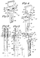
- Fig. 1 represents the two weaving harnesses 1 and 2, between which is mounted the selvedge device 3, here shown schematically, consisting of two parts 4 and 5 which move past each other, for example as described in US 4.478.256.
- the parts 4 and 5 are here attached to the respective suspension frames 6 to 9 of the weaving harnesses 1 and 2 by means of a number of detachable, movable mounting brackets 10 to 13.
- the special feature of the mounting according to the invention is that firstly, at least one of the mounting brackets 12 or 13, near the top end 14 or the bottom end 15 respectively or rear part 5, is in two parts and has a screw device 16 for attaching and tightening it onto the corresponding suspension frame 8, where said screw device 16 can be screwed in and out in a direction 17 oblique to the plane of the weaving harnesses 1 and 2, and secondly, the front part 4 of the selvedge device 3, or a mounting bracket 10 or 11 which forms part of it, has an opening 18 which offers a passage in the continuation of said screw device 16.
- all four mounting brackets 10 to 13 are in two parts, and both mounting brackets 10 and 11 of the front part 4 of the selvedge device 3 have an opening 18 as described above.
- the two-part mounting brackets 10 to 13 can for example consist of a hook-shaped part 19 which can be hooked behind the outside edge 20 of the corresponding suspension frame 6 to 9 respectively, and a base part 21 which can operate with the inside edge 22 of the corresponding suspension frame.
- the screw device 16 makes the connection between the two parts 19 and 21, such that by screwing up said screw device 16 the two parts are pulled towards each other and the corresponding suspension frame 6 to 9 is enclosed tightly between them.
- a U-shaped base part 21 such that the legs 23 and 24 of the U shape are situated in the plane of the corresponding weaving harness, while the hook-shaped part 19 fits into the U shape.
- the ends 25 and 26 of the legs 23 and 24 are contact parts, by means of which the base part 19 can be tightened against the inside edge 22 of the suspension frame 6 to 9 respectively.
- the necessary slots 27 and 28 are provided in the ends 25 and 26 in order to provide a seating for the corresponding suspension frame.
- the screw device 16 consists preferably of one centrally-mounted screw or bolt, which in the preferred embodiment of the above-mentioned mounting brackets 10 to 13 consists of a socket-head screw 29 whose head 30 is countersunk in the base part 21, in particular as shown in fig. 5.
- the parallel planes 31 and 32 of the parts 19 and 21 are preferably situated perpendicularly to the screw device 16.
- the parts 19 and 21 are preferably dimensioned so that when they fit round the suspension frames 6 to 9 a certain amount of play 33 remains between these parts 19 and 21.
- the side surfaces 34 and 35 in figs. 3 to 5 should preferably fit together.
- the opening 18 made at least in the front part 4 of the selvedge device 3 should preferably also be made in the base part 21 of the corresponding mounting bracket 10 or 11 respectively.
- the opening may be situated so that, in the position in which the weaving harnesses 1 and 2 are at the same height, the screw device 16 is accessible by means of a socket-head screw wrench or suchlike, as shown in figs. 2 and 5.
- All the mounting brackets 10 to 13 for the selvedge device 3 should preferably have a universal form as shown in figs. 3 to 5.
- the base part 21 here has a mounting part 36 on which the actual thread guide mechanisms 37 and 38 are mounted.
- the opening 18 can also consist of a long, vertical slot or suchlike along the length of part 4, which can simultaneously serve as the guide slot for the thread guide element 39, itself known, which is attached to the rear part 5.
- the angle A between the direction 17 and the plane of the weaving harnesses 1 and 2 can be from 15 to 45 degrees, and is preferably equal to 30 degrees.
- front and rear parts of the selvedge device 3 are only used in the description in order to differentiate between parts 4 and 5.
- said front part 4 can be nearer the shed on the weaving machine than the rear part 5 or vice versa, or in other words the side from which the screw device 16 can be screwed into the corresponding mounting bracket 10 to 13 can be either towards or away from the shed.
Landscapes
- Engineering & Computer Science (AREA)
- Textile Engineering (AREA)
- Looms (AREA)
Claims (11)
- Montage de dispositifs de formation de lisières sur des métiers à tisser, plus particulièrement pour des dispositifs de formation de lisières (3), qui consistent en deux parties (4, 5) qui se déplacent en passant l'une devant l'autre et qui sont montées l'une derrière l'autre, supportées sur deux harnais de tissage successifs (1, 2), dans lequel le montage consiste en un certain nombre de supports de montage (10, 11, 12, 13) qui fixent respectivement les deux parties (4, 5) du dispositif de formation de lisières (3) à proximité de leurs extrémités (14, 15) aux harnais de tissage correspondants (1, 2), comprenant au moins un dispositif à vis (16) pour attacher et fixer une desdites parties (4, 5) à un harnais de tissage (1, 2), que l'on peut visser et dévisser dans une direction (17) oblique par rapport au plan des harnais (1, 2), dans lequel ledit dispositif à vis (16) coopère avec au moins un des supports de montage (12, 13) d'une première partie (5) du dispositif de formation de lisières (3), et caractérisé en ce que la seconde partie (4) du dispositif de formation de lisières (3) ou d'un support de montage (10, 11) qui en fait partie, possède une ouverture (18) qui procure un passage s'étendant dans le prolongement dudit dispositif à vis (16).
- Montage selon la revendication 1, caractérisé en ce que la direction (17) dans laquelle le dispositif à vis (16) visse et dévisse, forme un angle (A) de 15 à 45 degrés par rapport au plan des harnais de tissage (1, 2).
- Montage selon la revendication 2, caractérisé en ce que l'angle susmentionné (A) est égal à 30 degrés.
- Montage selon l'une quelconque des revendications précédentes, caractérisé en ce qu'au moins le support de montage (12, 13) qui vient se disposer contre la partie arrière (5) du dispositif de formation de lisières et qui est muni du dispositif à vis susmentionné (16), consiste en un élément (19) en forme de crochet qui peut venir s'accrocher derrière le bord externe (20) du châssis de suspension correspondant (8, 9), et en un élément de base (21) qui peut venir se disposer contre le bord interne (22) du châssis de suspension (8, 9), dans lequel ledit dispositif à vis (16) réunit les deux éléments susmentionnés (19, 21) l'un à l'autre, de telles sorte qu'en vissant le dispositif à vis (16), les deux éléments (19, 21) sont tirés l'un vers l'autre et viennent se fixer sur la périphérie du châssis de suspension (8, 9).
- Montage selon l'une quelconque des revendications précédentes, caractérisé en ce que les dispositifs à vis (16) consistent en un boulon ou en une vis en position centrale par rapport aux supports de montage (12, 13).
- Montage selon la revendication 5, caractérisé en ce que le dispositif à vis (16) consiste en une vis à tête creuse (29), dont la tête (30) est chanfreinée dans l'élément de base susmentionné (21).
- Montage selon l'une quelconque des revendications 4 à 6, caractérisé en ce que l'élément de base (21) est en forme de U, muni de deux branches (23, 24) situées dans le plan du châssis correspondant (2), tandis que l'élément (19) en forme de crochet vient se disposer dans le U, les extrémités libres (25, 26) desdites branches (23, 24) formant les éléments de contact avec lesquels l'élément de base (21) peut être serré contre le bord interne (22) du châssis de suspension correspondant (8, 9).
- Montage selon la revendication 7, caractérisé en ce que les extrémités (25, 26) des branches (23, 24) de l'élément de base (21) en forme de U sont munies de fentes (27, 28) qui forment un siège pour le châssis de suspension correspondant (8, 9).
- Montage selon l'une quelconque des revendications 4 à 8, caractérisé en ce que l'ouverture susmentionnée (18) est réalisée dans l'élément de base (21) du châssis de suspension correspondant (10, 11).
- Montage selon l'une quelconque des revendications précédentes, caractérisé en ce que l'ouverture (18) est située de telle sorte qu elle se trouve dans le prolongement du dispositif à vis (16) chaque fois que les harnais (1, 2) se trouvent exactement à la même hauteur.
- Montage selon la revendication 1, caractérisé en ce que l'ouverture (18) pratiquée dans la première partie (4) du dispositif de formation de lisières (3) constitue la fente de guidage dans laquelle peut coulisser l'élément de guidage de fil (39), qui constitue un élément de la partie arrière (5) du dispositif de formation de lisières (3).
Applications Claiming Priority (2)
| Application Number | Priority Date | Filing Date | Title |
|---|---|---|---|
| BE8701388A BE1001287A3 (nl) | 1987-12-04 | 1987-12-04 | Zelfkantapparaatbevestiging bij weefmachines. |
| BE8701388 | 1987-12-04 |
Publications (2)
| Publication Number | Publication Date |
|---|---|
| EP0320030A1 EP0320030A1 (fr) | 1989-06-14 |
| EP0320030B1 true EP0320030B1 (fr) | 1993-02-03 |
Family
ID=3883005
Family Applications (1)
| Application Number | Title | Priority Date | Filing Date |
|---|---|---|---|
| EP88202523A Expired - Lifetime EP0320030B1 (fr) | 1987-12-04 | 1988-11-11 | Montage de dispositif de lisière pour métiers à tisser |
Country Status (3)
| Country | Link |
|---|---|
| EP (1) | EP0320030B1 (fr) |
| BE (1) | BE1001287A3 (fr) |
| DE (1) | DE3878190T2 (fr) |
Citations (1)
| Publication number | Priority date | Publication date | Assignee | Title |
|---|---|---|---|---|
| DE3336504C1 (de) * | 1983-10-07 | 1985-03-14 | Gebrüder Schmeing, 4280 Borken | Vorrichtung zur Herstellung einer Gewebe-Schnittleiste |
Family Cites Families (1)
| Publication number | Priority date | Publication date | Assignee | Title |
|---|---|---|---|---|
| DE3202006C2 (de) * | 1982-01-22 | 1984-04-05 | Grob & Co AG, 8810 Horgen, Zürich | Zwischenstrebe für einen Webschaft |
-
1987
- 1987-12-04 BE BE8701388A patent/BE1001287A3/nl not_active IP Right Cessation
-
1988
- 1988-11-11 EP EP88202523A patent/EP0320030B1/fr not_active Expired - Lifetime
- 1988-11-11 DE DE19883878190 patent/DE3878190T2/de not_active Expired - Fee Related
Patent Citations (1)
| Publication number | Priority date | Publication date | Assignee | Title |
|---|---|---|---|---|
| DE3336504C1 (de) * | 1983-10-07 | 1985-03-14 | Gebrüder Schmeing, 4280 Borken | Vorrichtung zur Herstellung einer Gewebe-Schnittleiste |
Also Published As
| Publication number | Publication date |
|---|---|
| BE1001287A3 (nl) | 1989-09-12 |
| DE3878190D1 (de) | 1993-03-18 |
| EP0320030A1 (fr) | 1989-06-14 |
| DE3878190T2 (de) | 1993-05-27 |
Similar Documents
| Publication | Publication Date | Title |
|---|---|---|
| CA1137608A (fr) | Boitier electrique | |
| US4456644A (en) | Cushioning body for the interior of a vehicle, or the like | |
| US5135341A (en) | Device for fastening an electronic equipment to a mounting wall | |
| US4705328A (en) | Mounting device for front members of drawers | |
| US4595245A (en) | Fastening device for front plates of drawers or the like | |
| CA2046976A1 (fr) | Dispositifs de fixation et ensemble de panneaux munis de ces dispositifs | |
| EP0320030B1 (fr) | Montage de dispositif de lisière pour métiers à tisser | |
| US6125505A (en) | Door closer and mounting bracket | |
| AU584208B2 (en) | System for mounting furniture on wallboard partitions | |
| EP0395132B1 (fr) | Mécanisme pour monter une pièce sur le battant d'un métier à tisser | |
| JP3408698B2 (ja) | 織機における対象部材の締結固定装置 | |
| JP3497544B2 (ja) | 部品の取付構造 | |
| US4687030A (en) | Heddle frame for a high speed weaving machine | |
| JPH0249375Y2 (fr) | ||
| GB2144974A (en) | A support bracket for a wall mounted rack system | |
| KR200154212Y1 (ko) | 벽걸이형 제품의 벽면 고정용 장치 | |
| JPS58185885A (ja) | ウインドウパネルとレギユレ−タとの連結部構造 | |
| JP3564828B2 (ja) | 織機における製織部品の取付装置 | |
| KR900008508Y1 (ko) | 체결용 브라켓트 | |
| JPH0354962Y2 (fr) | ||
| JP3586567B2 (ja) | フレキシブル固定装置およびラック | |
| KR890002993Y1 (ko) | 자동차 용 차광구 | |
| JPS584309Y2 (ja) | シャ−シの取り付け構造 | |
| EP0419437A1 (fr) | Moyens de fixation pour les tôles protectrices dans les métiers à tisser | |
| JPH0242188Y2 (fr) |
Legal Events
| Date | Code | Title | Description |
|---|---|---|---|
| PUAI | Public reference made under article 153(3) epc to a published international application that has entered the european phase |
Free format text: ORIGINAL CODE: 0009012 |
|
| AK | Designated contracting states |
Kind code of ref document: A1 Designated state(s): CH DE FR IT LI |
|
| 17P | Request for examination filed |
Effective date: 19890628 |
|
| 17Q | First examination report despatched |
Effective date: 19910926 |
|
| GRAA | (expected) grant |
Free format text: ORIGINAL CODE: 0009210 |
|
| AK | Designated contracting states |
Kind code of ref document: B1 Designated state(s): CH DE FR IT LI |
|
| ITF | It: translation for a ep patent filed | ||
| REF | Corresponds to: |
Ref document number: 3878190 Country of ref document: DE Date of ref document: 19930318 |
|
| ET | Fr: translation filed | ||
| PGFP | Annual fee paid to national office [announced via postgrant information from national office to epo] |
Ref country code: FR Payment date: 19931018 Year of fee payment: 6 |
|
| PGFP | Annual fee paid to national office [announced via postgrant information from national office to epo] |
Ref country code: CH Payment date: 19931020 Year of fee payment: 6 |
|
| PGFP | Annual fee paid to national office [announced via postgrant information from national office to epo] |
Ref country code: DE Payment date: 19931022 Year of fee payment: 6 |
|
| PLBE | No opposition filed within time limit |
Free format text: ORIGINAL CODE: 0009261 |
|
| STAA | Information on the status of an ep patent application or granted ep patent |
Free format text: STATUS: NO OPPOSITION FILED WITHIN TIME LIMIT |
|
| 26N | No opposition filed | ||
| PG25 | Lapsed in a contracting state [announced via postgrant information from national office to epo] |
Ref country code: LI Effective date: 19941130 Ref country code: CH Effective date: 19941130 |
|
| PG25 | Lapsed in a contracting state [announced via postgrant information from national office to epo] |
Ref country code: FR Effective date: 19950731 |
|
| REG | Reference to a national code |
Ref country code: CH Ref legal event code: PL |
|
| PG25 | Lapsed in a contracting state [announced via postgrant information from national office to epo] |
Ref country code: DE Effective date: 19950801 |
|
| REG | Reference to a national code |
Ref country code: FR Ref legal event code: ST |
|
| PG25 | Lapsed in a contracting state [announced via postgrant information from national office to epo] |
Ref country code: IT Free format text: LAPSE BECAUSE OF NON-PAYMENT OF DUE FEES Effective date: 20051111 |